
FENCE ENERGIZER
M35 M50 M120 M160
Instructions
Installatie instucties
Notice d’installation
Betriebsanleitung
Instrucciones
Monteringsinstrucktioner
Istruzioni per l’installazione
Instruções
- ENG
- NED
- FRA
- DEU
- ESP
- SVE
- ITA
- POR

PUBLISHED BY
Gallagher Group Limited
181 Kahikatea Drive, Private Bag 3026
Hamilton, New Zealand
www.gallagher.com
Copyright© Gallagher Group Limited 2023
All rights reserved. Patents pending.
Gallagher Small Mains Energizer User Manual for Animals
Électricateur de clôture pour animaux
3E1802 - Edion 11 - May 2023
DISCLAIMER: Whilst every eort has been made to ensure accuracy,
neither Gallagher Group Limited nor any employee of the company
shall be liable on any ground whatsoever to any party in respect of
decisions or acons they may make as a result of using this informaon.
In accordance with the Gallagher policy of connuing development,
design and specicaons are subject to change without noce.
Developed and manufactured by Gallagher Group Limited, and ISO
9001 2015 Cered Supplier.

Contents
English
Important Informaon ................................................................................................................ 5
How the Energizer works ........................................................................................................... 8
5-Step Installaon Guide ............................................................................................................ 9
Opons for wire and post spacings .......................................................................................... 13
Voltage check list ...................................................................................................................... 14
Materials and Tools ................................................................................................................... 15
Waste Electrical And Electronic Equipment .............................................................................. 15
Specicaons ............................................................................................................................ 16
Nederlands
Belangrijke informae .............................................................................................................. 17
Hoe de schrikdraadapparaat werkt ......................................................................................... 20
5-stappen installaegids ........................................................................................................... 21
Opes voor draad- en paalafstanden ....................................................................................... 25
Spanningschecklist .................................................................................................................... 26
Materialen en Gereedschap ..................................................................................................... 27
Afgedankte elektrische en elektronische apparaten ................................................................ 27
ProductSpecicaes ................................................................................................................. 28
Français
Informaon importante ............................................................................................................ 29
Comment fonconne l’électricateur ....................................................................................... 32
Guide d’installaon en 5 étapes ............................................................................................... 33
Choix des espacements des ls et poteaux .............................................................................. 37
Liste de contrôle de la tension .................................................................................................. 38
Matériel et Oullage ................................................................................................................. 39
Déchets d’équipements électriques et électroniques .............................................................. 39
Spécicaons du Produit .......................................................................................................... 40
Deutsch
Wichge Informaonen ............................................................................................................ 41
Arbeitsweise des Elektrozaungerätes ....................................................................................... 44
Installaonsanweisung in 5 Schrien ....................................................................................... 45
Oponen für Draht- und Pfahl-Abstände .................................................................................. 49
Spannungs-Prüiste .................................................................................................................. 50
Materialien und Werkzeuge ..................................................................................................... 51
Elektrische und elektronische Abfallprodukte .......................................................................... 51
Produkt-Spezizierungen .......................................................................................................... 52

Español
Información Importante ........................................................................................................... 53
Cómo funciona el energizador .................................................................................................. 56
5-Guía de instalación paso a paso ............................................................................................ 57
Opciones para el espacio entre postes y alambre .................................................................... 61
Lista de revisión del voltaje ...................................................................................................... 62
Materiales y herramientas ........................................................................................................ 63
Desecho de componentes y equipos electrónicos ................................................................... 63
Especicaciones del producto .................................................................................................. 64
Português
Informações importantes ......................................................................................................... 65
Como o Energizador funciona .................................................................................................. 68
Guia de Instalação em 5 Passos ................................................................................................ 69
Opções de Espaçamento de Fios e Hastes ............................................................................... 73
Lista de Vericação de Tensão .................................................................................................. 74
Ferramentas e Materials ........................................................................................................... 75
Especicações do Produto ........................................................................................................ 76
Descarte de Equipamentos Elétricos e Eletrônicos ................................................................... 76
Svenska
Vikg informaon ..................................................................................................................... 77
Så här fungerar aggregatet ...................................................................................................... 80
5-Stegs Installaons Guide ....................................................................................................... 81
Alternav för tråd-och stolpavstånd ......................................................................................... 85
Kontrollista spänning ................................................................................................................ 86
Material och Verktyg ................................................................................................................ 87
Avfall elektrisk och elektronisk utrustning ................................................................................ 87
Produktspecikaoner ............................................................................................................. 88
Italiano
Informazioni Importan ........................................................................................................... 89
Funzionamento del elericatore ........................................................................................... 92
Installazione in 5 mosse ............................................................................................................ 93
Distanze consigliate di pali e li ................................................................................................ 97
Diagramma di controlo ............................................................................................................. 98
Materiali ed Accessori .............................................................................................................. 99
Roamazione arezzature Eleriche od Eleroniche .............................................................. 99
Speciche tecniche ................................................................................................................. 100

5
English
Important Informaon
IMPORTANT INFORMATION
WARNING:
• Warning: The appliance is not intended for use by young
children or inrm persons without supervision.
• Young children should be supervised to ensure that they do not
play with the appliance.
• Regularly inspect the supply cord, cables, wires and energizer
for any damage. If found damaged in any way, immediately
cease use of the energizer and return it to a Gallagher
Authorised Service Centre for repair in order to avoid a hazard.
• Energizer must be installed in a shelter and the supply cord
must not be handled when the ambient temperature is below
+5 deg C.
• It is recommended that, in all areas where there is a likely presence of unsupervised children who will be
unaware of the dangers of electric fencing, that a suitably rated current liming device having a resistance
of not less than 500 ohms be connected between the energizer and the electric fence in this area.
• Check your local council for specic regulaons.
• Fence wiring should be installed well away from any telephone or telegraph line or radio aerial.
• Well maintained electric fences kept clear of vegetaon with high quality insulaon are extremely unlikely
to cause res. In mes of extreme re risk, disconnect energizer.
• Do not mount in places exposed to heat sources (e.g. a sun heated metal wall).
• Refer servicing to a Gallagher Authorised Service Centre.
• Do not connect two Energizers to the same earth system.
• If connected to a mains power circuit that doesn’t have a Residual Current Device (RCD), then a plug-in RCD
should always be used.
• Ensure the Energizer is fully protected from rain, condensaon and other sources of moisture.
• Ensure the Energizer has adequate venlaon.
• Energizers with a Standby mode may turn on or o without warning. The energizer must be disconnected
from the mains supply if it needs to be rendered fully inoperave.
• Electric animal fences and their ancillary equipment shall be installed,operated and maintained so that they
cause no electrical hazard to persons, animals or their surroundings.
• Do NOT become entangled in the fence. Avoid electric fence construcons that are likely to lead to the
entanglement of animals or persons.
• WARNING - INSTALLERS/USERS SHOULD NOTE:
Avoid contacng the fence with the head, mouth, neck or torso.
Do not climb over, through or under a mul-wire electric fence.
Use a gate or a specially designed crossing point.
• An electric animal fence shall not be supplied from two separate energizers or from independent fence
circuits of the same energizer.
• For any two separate electric animal fences, each supplied from a separate energizer independently med,
the distance between the wires of the two electric animal fences shall be at least 2.5m. If this gap is to be
closed, this shall be eected by means of electrically non-conducve material or an isolated metal barrier.
• Barbed wire or razor wire shall not be electried by an energizer.
• A non-electried fence incorporang barbed wire or razor wire may be used to support one or more
o-set electried wires of an electric animal fence. The supporng devices for the electried wires shall
be constructed so as to ensure that these wires are posioned at a minimum distance of 150 mm from the

6
English
Important Informaon
vercal plane of the non-electried wires. The barbed wire and razor wire shall be earthed at regular
intervals.
• Follow the energizer manufacturer’s recommendaons regarding earthing.
• The energizer earth electrode should penetrate the ground to a depth of at least 1 m (3 ) and not be
within 10 m (33 ) of any power, telecommunicaons or other system.
• Use high voltage lead-out cable in buildings to eecvely insulate from the earthed structural parts
of the building and where soil could corrode exposed galvanized wire. Do not use household electrical
cable.
• Connecng leads that are run underground shall be run in conduit of insulang material or else insulated
high voltage lead-out cable shall be used. Care must be taken to avoid damage to the connecng leads
due to the eects of animal hooves or tractor wheels sinking into the ground.
• Connecng leads shall not be installed in the same conduit as the mains supply wiring, communicaon
cables or data cables.
• Connecng leads and electric animal fence wires shall not cross above overhead power or
communicaon lines.
• Crossings with overhead power lines shall be avoided wherever possible. If such a crossing cannot be
avoided it shall be made underneath the power line and as nearly as possible at right angles to it.
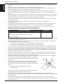
• If connecng leads and electric animal fence wires are installed near an overhead power line, the
clearances shall not be less than those shown in the table following.
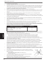
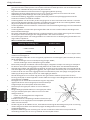
Minimum clearances from power lines for electric animal fences
Power line Voltage V Clearance m
Less than or equal to 1 000 3
Greater than 1 000 and less than or equal to 33 000 4
Greater than 33 000 8
• If connecng leads and electric animal fence wires are installed near an overhead power line, their height
above the ground shall not exceed 3 m
This height applies either side of the orthogonal projecon of the outermost conductors of the power
line on the ground surface, for a distance of:
- 2 m for power lines operang at a nominal voltage not exceeding 1 000 V;
- 15 m for power lines operang at a nominal voltage exceeding 1 000 V.
• Electric animal fences intended for deterring birds, household pet containment or training animals such
as cows need only be supplied from low output energizers to obtain sasfactory and safe performance.
• In electric animal fences intended for deterring birds from roosng on buildings, no electric fence wire
shall be connected to the energizer earth electrode. A warning sign shall be ed to every point where
persons may gain ready access to the conductors.
• Where an electric animal fence crosses a public pathway, a non-electried gate shall be incorporated
in the electric animal fence at that point or a crossing by means of sles shall be provided. At any such
crossing, the adjacent electried wires shall carry warning signs.
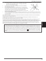
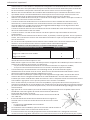
• Any part of an electric animal fence that is installed along a public road or pathway shall be idened
by electric fence warning signs (G6020) at regular intervals that
are securely fastened to the fence posts or rmly clamped to the
fence wires.
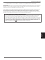
• The size of the warning sign shall be at least 100mm x 200mm.
• The background colour of both sides of the warning sign shall
be yellow. The inscripon on the sign shall be black and shall be
either:
- the substance of “CAUTION: Electric Fence” or,
- the symbol shown:
• The inscripon shall be indelible, inscribed on both sides of the
warning sign and have a height of at least 25mm.
• Ensure that all mains operated, ancillary equipment connected to the electric animal fence circuit
provides a degree of isolaon between the fence circuit and the supply mains equivalent to that provided
by the energizer.
• Protecon from the weather shall be provided for the ancillary equipment unless this equipment is
cered by the manufacturer as being suitable for use outdoors, and is of a type with a minimum degree
of protecon IPX4.

7
English
Important Informaon
This energizer complies with internaonal safety regulaons and is manufactured to internaonal standards.
Gallagher reserves the right to make changes without noce to any product specicaon to improve reliability,
funcon or design. E & OE.
The author thanks the Internaonal Electrotechnical Commission (IEC) for permission to reproduce Informaon
from its Internaonal Publicaon 60335-2-76 Ed.2.2 (2013) - BB1. All such extracts are copyright of IEC, Geneva,
Switzerland. All rights reserved. Further informaon on the IEC is available from www.iec.ch. IEC has no responsibility
for the placement and context in which the extracts and contents are reproduced by the author, nor is IEC in any way
responsible for the other content or accuracy therein.
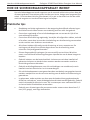
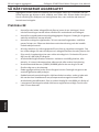
SERVICE OF DOUBLE-INSULATED APPLIANCES
In a double-insulated controller, two systems of insulaon are provided instead of grounding. No equipment
grounding means is provided in the supply cord of a double-insulated controller, nor should a means for
equipment grounding be added to the controller. Servicing a double-insulated controller requires extreme
care and knowledge of the system, and should be done only by qualied service personnel. Replacement parts
of a double insulated controller must be idencal to the parts they replace. A double insulated controller is
marked with the words “DOUBLE INSULATION” or “DOUBLE INSULATED”. The symbol for double insulaon
may also be marked on the appliance.

English
Gallagher 3E1802 Small Mains Energizer User Manual
8
How the energizer works
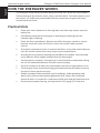
HOW THE ENERGIZER WORKS
The energizer sends electrical pulses along the fence line, about one second apart.
These pulses give the animal a short, sharp, but safe shock. The shock doesn’t harm
the animal. It is suciently memorable that the animal never forgets the shock,
and will avoid the fence.
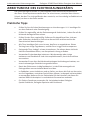
Practical Hints
• Check your local ordinance on fencing laws: local laws may require a permit
before use.
• Periodically check that the energizer is operang by checking that the
indicator light is ashing.
• Check the fence periodically. Remove any fallen branches, weeds or shrubs
because these will cause the fence to short out and will reduce animal
control.
• All animals need me to learn to respect the fence. It may take several days to
train the animal and the fence may require minor adjustments.
• Animals that are prone to jumping may be dicult to conne. You may need
to try dierent fence heights to determine the best height.
• Use top quality insulators: low quality or cracked insulators and plasc tubing
are not recommended because they will cause shorng.
• Use joint clamps on all steel wire connecons to ensure a high quality circuit.
• This energizer must be earthed using galvanised metal earth stakes to ensure
the electric fence works correctly.
• Double Insulated Cable should be used in buildings, under gateways and
where soil could corrode exposed galvanised wire. Never use household
electrical cable. It is made for a maximum of 600 volts and will leak electricity.
• On permanent power fencing, use high tensile 12.5 gauge (2.5 mm) wire.

English
Gallagher 3E1802 Small Mains Energizer User Manual
9
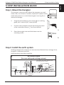
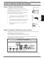
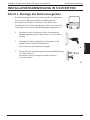
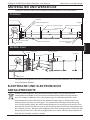
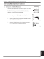
5-Step Installaon Guide
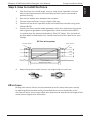
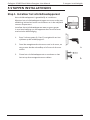
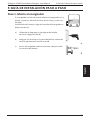
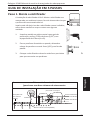
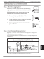
The energizer is easy to install. Mount the energizer on a wall,
under cover, out of reach of children, adjacent to a power outlet.
Install where there is no risk of the energizer incurring re or
mechanical damage.
1. Using the the template on the centre page as a drilling
guide, drill 2 x 4mm (5/32”) holes (A & B).
2. Fix the screws provided into the wall leaving the head
of the screw about 3mm (1/8”) out from the wall.
3. Place the energizer over and slide down onto the
mounng screws.
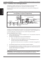
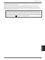
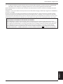
Buildings and gates for example, can become electried with fence voltages if the
energizer is improperly earthed.
Follow earthing instrucons carefully.
HobbyMaster
M50
Earth Clamp
(G8760)
The animal must touch the wire and
the ground to feel a shock
Live
GREEN
RED
Earth Stake
(G8790)
Live
Live
a
b
a

English
Gallagher 3E1802 Small Mains Energizer User Manual
10
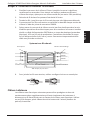
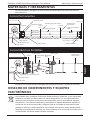
5-Step Installaon Guide
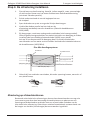
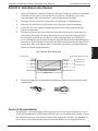
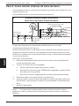
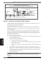
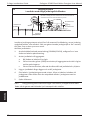
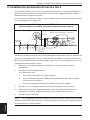
The most eecve place for an earth system is in connuously damp soil, see
illustraon a. For dry areas with poor earthing condions, see illustraon b.
Install the earth system at least 10m (33) from any power supply earth peg,
underground telephone or power cable. Drive one 2m (6) earth stake into the
ground, unl only 5cm (2”) remain above the ground.
To aach the earth cable:
1. Using double insulated cable, remove 5cm (2”) of plasc coang from one end
of the cable wire.
2. Connect the earth wire to the energizer.
a. Bend the end of the wire to form a loop.
b. Unscrew the green (EARTH) terminal on the energizer and insert the loop
of wire between the washers.
c. Screw the terminal closed, ensuring the wire is rmly clamped.
3. Lay out the cable down walls and out to the earth stake.
4. Aach the cable to the earth stake by removing 10cm (4”) of insulaon from
the cable at the earth stake, then clamp the exposed wire to the stake using an
earth clamp.
5. Tighten the clamp.
Note: Poor grounding can cause interference on telephone lines, radios and
televisions. This can be recognised by a clicking sound on telephones.
HobbyMaster
M50
The animal must touch both a live wire and
the earth wire to feel an eecve shock
Earth
Live
Live
Earth Clamp
(G8760)
GREEN
RED
Earth Stake
(G8790)
b

English
Gallagher 3E1802 Small Mains Energizer User Manual
11
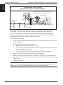
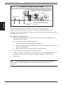
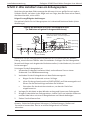
5-Step Installaon Guide
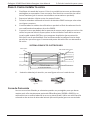
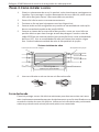
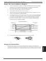
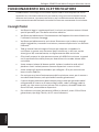
1. Plan the fence line. Avoid rough, stony or steep areas if possible. For best
electric fence performance use mul-wire (at least 3 wires connected in
parallel) fencing.
2. Run out the boom wire between the end posts.
3. Tension wires unl there is only a slight visible sag.
4. Connect all live wires in parallel at the end of each fence secon using Joint
Clamps G6030.
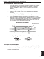
5. Connect the fence system under gateways, rather than overhead. Do not use
electric gates to get power across gateways. Install Lead-out Cable G6270
in a plasc pipe (for physical protecon), 30cm (12”) deep. Turn the ends of
the pipe down to keep water out. Connect each end of the cable to the Joint
Clamps.
6. When joining wires under tension, use a gure eight or reef knot.
Exisng non-electric fences can be protected to last for many more years simply
by aaching oset brackets and an electried wire on one or both sides of the
non-electric fence. Use a single oset wire, posioned at two thirds the height of the
animal (chest height) to be controlled.
Cut-out switch Joint clamps
Live
Live cable
300mm (12”) deep
Live
Live
Figure Eight Reef Knot

English
Gallagher 3E1802 Small Mains Energizer User Manual
12
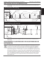
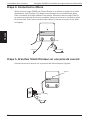
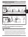
5-Step Installaon Guide
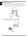
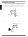
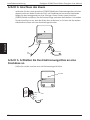
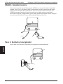
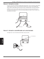
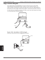
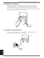
Connect the energizer’s red (FENCE) terminal to the fence using double insulated
cable. Remove 5cm (2”) of plasc coang from one end of the cable. Bend the end
of the wire to form a loop. Unscrew the red (FENCE) terminal and insert the loop of
wire between the washers. Screw the terminal closed, ensuring the wire is rmly
clamped. Aach the other end of the cable to the fence using a joint clamp.
Check that the light on the front of the energizer is ashing.
Red
Green
To fence
To earth
Light

English
Gallagher 3E1802 Small Mains Energizer User Manual
13
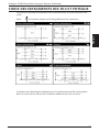
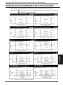
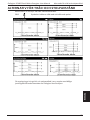
Opons for wire & post spacings
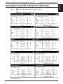
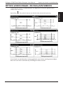
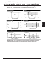
OPTIONS FOR WIRE AND POST SPACINGS
These gures are guidelines only for at country condions.
Note: Symbol indicates a live, pulse-carrying wire
Symbol indicates an earth wire
For wire and post spacings in dry areas with poor earthing condions, see your
Gallagher dealer.

English
Gallagher 3E1802 Small Mains Energizer User Manual
14
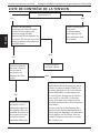
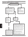
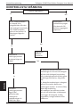
Voltage Checklist
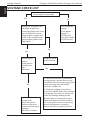
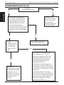
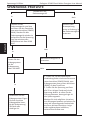
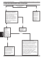
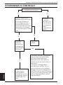
VOLTAGE CHECK LIST
No
Is the energizer operang?
Test the earth
system.
Is the ground
voltage more
than
200 volts?
Unplug the energizer from
the power supply and
remove the fence wire from
the red (FENCE) terminal.
Plug energizer in again and
check. Is the voltage across
the terminals greater than
5000 volts?
1. Check the electrical connecons
are secure eg. from the fence to the
red (FENCE) terminal, from the ground
system to the green (GROUND)
terminal, at gates etc.
2. Check the voltage on the fence
every 33m (100). Note if the voltage
is dropping. The closer to a fault, the
lower the voltage reading will be.
Become aware of things that cause
faults and always be on the lookout
for: stray pieces of wire on the fence,
heavy undergrowth, cracked or
broken insulators, broken wires etc.
Test the power
supply.
If the power
supply is
OK then the
energizer needs
to be serviced.
Improve the earth
system: add
galvanised earth
stakes to the earth
system unl the earth
voltage is
200 volts or below.
Energizer needs
to be serviced.
Yes No
Yes No
Yes

English
Gallagher 3E1802 Small Mains Energizer User Manual
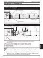
15
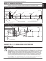
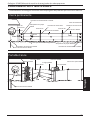
MATERIALS AND TOOLS
Gallagher dealers oer a complete range of products for your power fence.
HobbyMaster
M50
Strain Post
Strain Post
Strain Insulators G6791 or G6781
Line Post
Wire Tighteners G6430
Joint Clamps G6030
Cut-out Switch G6076
Warning Sign G6020
Line Post Insulators
HOT
HOT
HOT
Strain Insulators G6791 or G6781
Joint Clamps G6030
Permanent Fence
GREEN
Earth Stake G8790
Earth Clamp G8760
RED
Line Post
Line Post Insulators
HobbyMaster
M50
Earth Stake G8790
Reel G6110
Poly Wire G6201
Treadin G6370
Insulgrip G6063
Econoreel G6160 Pigtail
G6420
Portable Fence
Turbo Wire G6205
GREEN
RED
For fence specicaons and design contact your Gallagher dealer.
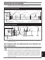
WASTE ELECTRICAL AND ELECTRONIC
EQUIPMENT
This symbol on the product indicates that this product, packaging and with special
care of the baery must not be disposed of with other waste. Instead, it is your
responsibility to dispose of your waste equipment by handing it over to a designated
collecon point for the recycling of waste electrical and electronic equipment. The
separate collecon and recycling of your waste equipment at the me of disposal
will help conserve natural resources and ensure that it is recycled in a manner that
protects human health and the environment. For more informaon about where
you can drop o your waste equipment for recycling, please contact your local city
recycling oce or the dealer from whom you purchased the product.

English
Gallagher 3E1802 Small Mains Energizer User Manual
16
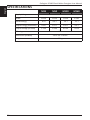
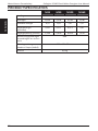
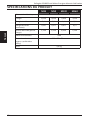
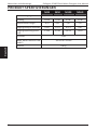
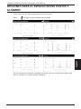
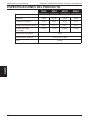
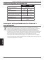
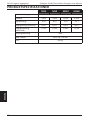
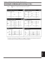
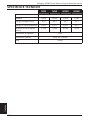
SPECIFICATIONS
M35 M50 M120 M160
Supply Voltage 230 V 50 Hz
Power 0.6 W 0.6 W 0.9 W 1.6 W
Stored Energy 0.4 J 0.6 J 1.4 J 1.5 J
Output Energy (maximum) 0.23 J 0.27 J 0.47 J 0.6 J
Output Voltage (no load) 5.3 kV 5.9 kV 6.8 kV 7.6 kV
IP Rang IPX4
Dimensions (HxWxD) 220 x 174 x 76 mm
Weight 0.8 kg

17
Belangrijke Informae
Nederlands
BELANGRIJKE INFORMATIE
WAARSCHUWING:
• Waarschuwing: Dit apparaat en de hierop aangesloten
afrastering is niet bedoeld voor het gebruik zonder toezicht
door jonge kinderen of handelingonbekwame personen
• Jonge kinderen dienen onder toezicht te staan, om er zeker van
te zijn dat ze niet met het apparaat of afrastering spelen.
• Controleer regelmag of de toevoerdraad, kabels, draden en
het schrikdraadapparaat niet zijn beschadigd. Indien er enige
schade wordt opgemerkt, stop dan onmiddellijk het gebruik
van het schrikdraadapparaat en stuur het terug naar een
erkende reparaedienst van Gallagher om gevaarlijke situaes
te vermijden.
• Het schrikdraadapparaat moet worden geïnstalleerd in een
schuur en het snoer mag niet worden aangeraakt wanneer de
temperatuur beneden de 5 graden is.
• Overal waar er een kans op de aanwezigheid van kinderen zonder toezicht bestaat die niet op de hoogte
zijn van de gevaren van elektrische afrasteringen, is het aan te raden om tussen het schrikdraadapparaat
en de afrastering in de betreende zone een begrenzing aan te sluiten met een weerstand van niet minder
dan 500 ohm om het adequate nominale vermogen te beperken.
• Verieer ook of er volgens uw lokale wetgeving nog specieke regels zijn.
• Afrasteringsdraden moeten op ruime afstand van telefoon- of telegraaijnen of radioantennes worden
geïnstalleerd.
• Bij goed onderhouden elektrische afrastering die vrij van begroeiing gehouden worden en goed geïsoleerd
zijn, is het risico op brand extreem laag. In jden met extreem hoog brandrisico dienen schrikdraadappara-
ten losgekoppeld te worden.
• Niet monteren op plaatsen die blootgesteld zijn aan warmtebronnen (zoals een opgewarmde muur door
de zon).
• Laat reparae en onderhoud enkel door erkend servicepersoneel van Gallagher uitvoeren.
• Bevesg niet twee schrikdraadapparaten op dezelfde aarding.
• Indien aangesloten op een 220V circuit dat niet beschikt over een aardlekschakelaar (RCD), dan zal er ten
alle jde een plug in –RCD gebruikt moeten worden.
• Zorg ervoor dat het schrikdraadapparaat volledig beschermd is tegen regen, condensae en andere
vochtbronnen.
• Zorg ervoor dat het schrikdraadapparaat een goede venlae hee.
• Schrikdraadapparaten met een Standby modus kunnen in- of uitgeschakeld worden zonder waarschuwing.
Het schrikdraadapparaat moet worden los gekoppeld van het stroomnet.
• Elektrische afrasteringen moeten zo geïnstalleerd en bediend worden dat ze geen elektrisch gevaar voor
personen, dieren of hun omgeving vormen.
• Voorkom verstrengeling in de afrastering. Vermijd elektrische afrasteringsconstruces die mogelijk tot
verstrengeling van dieren of personen kunnen leiden.
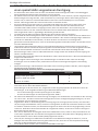
• WAARSCHUWING - MONTEURS/GEBRUIKERS DIENEN EROP TE
LETTEN DAT: Vermijd aanraking van elektrische afrasteringen
met het hoofd, mond, nek of het bovenlijf. Klim niet over, door

18
Belangrijke Informae
Nederlands
of onder een elektrische meerdraads-afrastering. Gebruik een
poort of een speciaal daarvoor geplaatste doorgang.
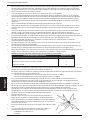
• Een elektrische afrastering mag niet door twee verschillende schrikdraadapparaten gevoed worden of
door onaankelijke afrasteringscircuits aangesloten op worden hetzelfde schrikdraadapparaat.
• Voor elk van twee afzondelijke afrasteringen, elk gevoed door een afzonderlijk, onaankelijk pulserend
schrikdraadapparaat, moet de afstand tussen de draden van de twee elektrische afrasteringen minimaal
2.5 m (8 vt) bedragen. Indien deze opening moet kunnen worden afgesloten, gebruik dan elektrisch
niet-geleidend materiaal of een geïsoleerde metalen afsluing.
• Gebruik in een elektrische afrastering geen prikkel- of scheermesdraad als geleider.
• Een niet-geëlectriceerde prikkeldraad- of scheermesdraad-afrastering mag als drager gebruikt worden
voor één of meer op afstand geplaatste elektrische afrasteringsdraden. Het dragende systeem voor deze
onder stroom staande afrasteringsdraden moeten dusdanig geconstrueerd zijn dat een minimale afstand
van 150 mm (6”) uit het vercale vlak van de stroomvrije prikkeldraad-of scheermesafrastering wordt
bewaard. De prikkel- en scheermesafrastering moeten op regelmage afstanden geaard worden.
• Houd u betreende de aarding aan de aanbevelingen van de producent van het schrikdraadapparaat.
• De aarde van het schrikdraadapparaat moet minimaal tot 1m diep in de grond gestoken worden en niet
binnen een afstand van 10m van andere aardingssystemen van het lichtnet-, telecommunicae- of andere
systemen.
• Gebruik aanvoerkabel met hoogspanning-isolae binnen gebouwen voor een eeceve isolae en
gebruik deze kabel ook op plaatsen waar blootliggende gegalvaniseerde draad eventueel aan corrosie
onderhevig is Gebruik hiervoor geen kabel of snoer voor normale huishoudelijke toepassingen.
• Ondergrondse aansluitgeleiders moeten in een mantel uit geïsoleerd materiaal worden geplaatst
of er dient kabel met hoogspanningsisolae worden gebruikt. Let erop dat er geen schade aan de
aansluitdraden kan ontstaan door het in de grond zakken van hoeven van vee of door tractorwielen.
• Aansluitleidingen voor de afrastering mogen niet door dezelfde kabelgoot worden gevoerd waarin
netspanningskabels of communicae-of datakabels liggen.
• Aansluitleidingen en draden van een elektrische afrastering mogen niet over bovengrondse stroom-of
communicaeleidingen heen lopen.
• Indien mogelijk moeten afrasteringen niet onder bovengrondse hoogspanningsleidingen aang elegd
worden. Indien dit niet kan worden vermeden, dan dient de afrastering de bovengrondse leiding zo haaks
te mogelijk kruisen.
• Indien aansluitkabels en draden van een elektrische afrastering in de buurt van bovengrondse
lichtnetleidingen worden geïnstalleerd, dan mogen de onderlinge afstanden niet kleiner zijn dan wat
hieronder wordt aangegeven:
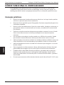
Minimale afstand tussen hoogspanningsleidingen en elektrische afrasteringen
Spanning hoogspanningsleiding Afstand m
≤ 1 000 3
> 1 000 ≥ 33 000 4
> 33 000 8
• Indien aansluitkabels en draden van elektrische afrasteringen in de buurt van bovengrondse leidingen
worden geïnstalleerd, mag de bovengrondse hoogte niet groter zijn dan 3 m (9 vt).
Deze hoogte geldt aan beide kanten van de loodrechte projece op de grond vanuit de buitenste geleiders
van de hoogspanningslijn, op een afstand van:
- 2 m (6 ) voor stroomleidingen met een nominale spanning van niet meer dan 1000 V;
- 15m (48) voor stroomleidingen met een nominale spanning van meer dan 1000 V.
• Voor elektrische afrasteringen bedoeld om vogels af te schrikken, huisdieren tegen te houden of
te trainen, zoals koeien, zijn schrikdraadapparaten met slechts een laag vermogen nodig om een
bevredigend en veilig resultaat te verkrijgen.
• Vogelafschrikking: Indien het schrikdraadapparaat gebruikt wordt om een systeem van elektrische
geleiders te voeden waarmee wordt tegengegaan dat vogels op gebouwen rusten, dan mag geen
elektrische geleider daarvan geaard worden. Duidelijke waarschuwingsborden moeten op elke plaats
worden bevesgd waar personen directe toegang hebben tot de elektrische geleiders. Een schakelaar
moet worden geïnstalleerd om het schrikdraadapparaat van alle polen van de zijn voedingslijn af te
schakelen.
• Indien een elektrische afrastering een publiek pad kruist, moet een spanningsvrije poort in de elektrische
afrastering worden geplaatst of moet er een overstapplaats aangebracht worden. Bij deze kruisingen

19
Belangrijke Informae
Nederlands
moeten de naburige geëlectriceerde draden een waarschuwingsbord hebben (G602).
• Van alle delen van het raster die zich langs de openbare weg bevinden, moeten de bordjes stevig
bevesgd zijn aan de palen of goed vastgeklemd zijn aan de draden.
• De afmengen van het waarschuwingsbordje moeten tenminste
100mm x 200mm bedragen.
• De kleur moet aan beide zijden geel zijn en de beleering moet zwart
zijn met de volgende inhoud:
- “PAS OP: SCHRIKDRAAD!” of,
- Het onderstaande symbool:
• De tekst moet vermeld staan aan beide zijden van het
waarschuwingsbordje en een hoogte hebben van tenminste 25mm.
• Zorg ervoor dat alle gebruikte lichtnetgevoede neveninstallaes, die
met de elektrische afrastering zijn verbonden, minimaal dezelfde mate van isolae tussen de aangesloten
afrastering en het lichtnet hee hee als waar het schrikdraadapparaat in voorziet.
• Bescherming tegen weersinvloeden moet worden geboden voor de bijbehorende apparatuur, tenzij deze
apparatuur is gecerceerd door de fabrikant als zijnde geschikt voor gebruik buitenshuis en is voorzien
van minimaal een IPX4 keur.
Dit schrikdraadapparaat voldoet aan de internaonale veiligheidsvoorschrien en is volgens internaonale
normen geproduceerd.
Gallagher behoudt zich het recht voor om zonder voorafgaande mededeling productspecicaes te veranderen
om de betrouwbaarheid, funconaliteit of het design te verbeteren. E & OE.
De auteur bedankt de Internaonal Electrotechnical Commission (IEC) voor toestemming voor het reproduceren van
informae uit de Internaonale Publicae 60335-2-76 ed.2.2 (2013). Alle extracten vallen onder copyright IEC, Geneva,
Switzerland. All rights reserved. Meer informae mbt IEC is beschikbaar op www.iec.ch. Het IEC is niet verantwoordelijk
voor de context waarin/waarvoor de schrijver deze reproduce hee gebruikt. Ook is het IEC niet verantwoordelijk voor
de rest van de inhoud of de correctheid hiervan.
SERVICE AAN DUBBEL GEISOLEERDE TOESTELLEN
Bij een dubbel geïsoleerd schrikdraadapparaat is voorzien in twee isolaesystemen in plaats van aarding. Geen
aarding wil hier zeggen dat er geen netsnoer met randaarde wordt gebruikt, en dat er ook naderhand geen
voorzieningen voor aarding op het schrikdraadapparaatmag worden aangebracht. Het servicen van een dubbel
geïsoleerd apparaat vereist zorgvuldigheid en goede kennis van het systeem en dient dus alleen te worden
gedaan door gekwaliceerd service-personeel. Defecte onderdelen dienen door gelijkwaardige onderdelen
te worden vervangen. Een dubbel geïsoleerde bediening is gemarkeerd met de woorden ‘Dubbele isolae’ of
‘Dubbel geïsoleerd’. Het symbool voor dubbele isolae mag ook worden gebruikt op het apparaat.

20
Nederlands
Gallagher 3E1802 Small Mains Energizer User Manual
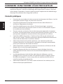
Hoe de schrikdraadapparaat werkt
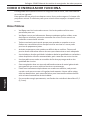
HOE DE SCHRIKDRAADAPPARAAT WERKT
Het-schrikdraadapparaat zendt ongeveer om de seconde elektrische pulsen door de
afrasteringsdraad. Deze pulsen geven het dier een korte, hevige maar ongevaarlijke
schok. De schok doet het dier geen kwaad. Hij is wel zo sterk dat het dier de schok
nooit zal vergeten en het de afrastering zal vermijden.
Praktische tips
• Raadpleeg uw lokale reglementen in de wetgeving betreende afrasteringen:
de lokale voorschrien kunnen een toelang vereisen vóór het gebruik.
• Controleer regelmag of het schrikdraadapparaat correct werkt: kijk of het
controlelampje knippert.
• Controleer de afrastering regelmag. Verwijder alle afgevallen takken, onkruid
of struiken, want deze kunnen de uitschakeling van de afrastering veroorzaken
en de controle over de dieren verminderen.
• Alle dieren hebben jd nodig om de afrastering te leren respecteren. De
training van de dieren kan enkele dagen duren en de afrastering moet
misschien lichtjes bijgesteld worden.
• Dieren die gemakkelijk springen zijn soms moeilijk op te sluiten. Mischien
moet u verschillende afrasteringshoogten uitproberen om de beste hoogte te
bepalen.
• Gebruik isolators van de beste kwaliteit: isolators van mindere kwaliteit of
gebarsten isolators en plasc buizen moeten worden vermeden omdat ze
kortsluing zullen veroorzaken.
• Gebruik verbindingsklemmen voor alle verbindingen van staaldraad, om de
kwaliteit van het elektrische circuit te waarborgen.
• Dit schrikdraadapparaat moet geaard worden met behulp van gegalvaniseerde
metalen aardpennen om de correcte werking van de elektrische afrastering te
garanderen.
• In gebouwen, onder oprien en daar waar de bodem blote gegalvaniseerde
draad kan corroderen, moet dubbelgeïsoleerde kabel worden gebruikt. Gebruik
nooit huishoudelijk elektrisch snoer. Dit is ontworpen voor maximaal 600 volt
en het zal elektriciteitslekken veroorzaken.
• Gebruik voor afrasteringen die permanent onder stroom staan draad van 2,5
mm (12.5 gauge), met hoge treksterkte.
La pagina sta caricando ...
La pagina sta caricando ...
La pagina sta caricando ...
La pagina sta caricando ...
La pagina sta caricando ...
La pagina sta caricando ...
La pagina sta caricando ...
La pagina sta caricando ...
La pagina sta caricando ...
La pagina sta caricando ...
La pagina sta caricando ...
La pagina sta caricando ...
La pagina sta caricando ...
La pagina sta caricando ...
La pagina sta caricando ...
La pagina sta caricando ...
La pagina sta caricando ...
La pagina sta caricando ...
La pagina sta caricando ...
La pagina sta caricando ...
La pagina sta caricando ...
La pagina sta caricando ...
La pagina sta caricando ...
La pagina sta caricando ...
La pagina sta caricando ...
La pagina sta caricando ...
La pagina sta caricando ...
La pagina sta caricando ...
La pagina sta caricando ...
La pagina sta caricando ...
La pagina sta caricando ...
La pagina sta caricando ...
La pagina sta caricando ...
La pagina sta caricando ...
La pagina sta caricando ...
La pagina sta caricando ...
La pagina sta caricando ...
La pagina sta caricando ...
La pagina sta caricando ...
La pagina sta caricando ...
La pagina sta caricando ...
La pagina sta caricando ...
La pagina sta caricando ...
La pagina sta caricando ...
La pagina sta caricando ...
La pagina sta caricando ...
La pagina sta caricando ...
La pagina sta caricando ...
La pagina sta caricando ...
La pagina sta caricando ...
La pagina sta caricando ...
La pagina sta caricando ...
La pagina sta caricando ...
La pagina sta caricando ...
La pagina sta caricando ...
La pagina sta caricando ...
La pagina sta caricando ...
La pagina sta caricando ...
La pagina sta caricando ...
La pagina sta caricando ...
La pagina sta caricando ...
La pagina sta caricando ...
La pagina sta caricando ...
La pagina sta caricando ...
La pagina sta caricando ...
La pagina sta caricando ...
La pagina sta caricando ...
La pagina sta caricando ...
La pagina sta caricando ...
La pagina sta caricando ...
La pagina sta caricando ...
La pagina sta caricando ...
La pagina sta caricando ...
La pagina sta caricando ...
La pagina sta caricando ...
La pagina sta caricando ...
La pagina sta caricando ...
La pagina sta caricando ...
La pagina sta caricando ...
La pagina sta caricando ...
La pagina sta caricando ...
La pagina sta caricando ...
La pagina sta caricando ...
La pagina sta caricando ...
-
 1
1
-
 2
2
-
 3
3
-
 4
4
-
 5
5
-
 6
6
-
 7
7
-
 8
8
-
 9
9
-
 10
10
-
 11
11
-
 12
12
-
 13
13
-
 14
14
-
 15
15
-
 16
16
-
 17
17
-
 18
18
-
 19
19
-
 20
20
-
 21
21
-
 22
22
-
 23
23
-
 24
24
-
 25
25
-
 26
26
-
 27
27
-
 28
28
-
 29
29
-
 30
30
-
 31
31
-
 32
32
-
 33
33
-
 34
34
-
 35
35
-
 36
36
-
 37
37
-
 38
38
-
 39
39
-
 40
40
-
 41
41
-
 42
42
-
 43
43
-
 44
44
-
 45
45
-
 46
46
-
 47
47
-
 48
48
-
 49
49
-
 50
50
-
 51
51
-
 52
52
-
 53
53
-
 54
54
-
 55
55
-
 56
56
-
 57
57
-
 58
58
-
 59
59
-
 60
60
-
 61
61
-
 62
62
-
 63
63
-
 64
64
-
 65
65
-
 66
66
-
 67
67
-
 68
68
-
 69
69
-
 70
70
-
 71
71
-
 72
72
-
 73
73
-
 74
74
-
 75
75
-
 76
76
-
 77
77
-
 78
78
-
 79
79
-
 80
80
-
 81
81
-
 82
82
-
 83
83
-
 84
84
-
 85
85
-
 86
86
-
 87
87
-
 88
88
-
 89
89
-
 90
90
-
 91
91
-
 92
92
-
 93
93
-
 94
94
-
 95
95
-
 96
96
-
 97
97
-
 98
98
-
 99
99
-
 100
100
-
 101
101
-
 102
102
-
 103
103
-
 104
104


in altre lingue
- français: Gallagher M35 Mode d'emploi
- español: Gallagher M35 Instrucciones de operación
- Deutsch: Gallagher M35 Bedienungsanleitung
- Nederlands: Gallagher M35 Handleiding
- português: Gallagher M35 Instruções de operação
Documenti correlati
-
Gallagher M350 Istruzioni per l'uso
-
 Gallagher M950 Istruzioni per l'uso
-
Gallagher M5800i Istruzioni per l'uso
-
Gallagher S10 Istruzioni per l'uso
-
 Gallagher S30 LITHIUM Istruzioni per l'uso
-
Gallagher S12 Istruzioni per l'uso
-
Gallagher S6 Lithium Istruzioni per l'uso
-
 Gallagher S6 Istruzioni per l'uso
-
-
Gallagher G50700 Istruzioni per l'uso


