
1/8
Divisione della BETA UTENSILI SPA, Via Volta, 18 - 20845 SOVICO (MB) ITALY Tel. +39.039.20771-Fax + 39.039.2010742
SPECIFICA PRODOTTO
ISTRUZIONI PER L’USO E LA MANUTENZIONE
Informazioni tecniche
Condizioni d’uso previste e limiti operativi
Prescrizioni per gli operatori
Rischi residui
Modalità e frequenza delle ispezioni periodiche d’idoneità
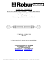
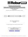
TENDITORE A DUE OCCHI
ART. 8105
La lingua originale della presente specifica è quella Italiana.
Sede produttiva Accessori per funi ROBUR
Zona Industriale – C.da S. Nicola
67039 SULMONA (L’AQUILA)
Tel. +39.0864.2504.1 – Fax +39.0864.253132
www.beta-tools.com – info@roburitaly.com
R/SP/8105/10
Data 22/07/2020

2/8
Divisione della BETA UTENSILI SPA, Via Volta, 18 - 20845 SOVICO (MB) ITALY Tel. +39.039.20771-Fax + 39.039.2010742
1) CARATTERISTICHE TECNICHE
Materiale / Norma di riferimento:
CANAULA acciaio C45 - UNI EN 10083-2
ANELLI acciaio C45 - UNI EN 10083-2
DADO acciaio classe resistenza 4 - UNI EN 20898-2
Trattamento Termico:
CANAULA normalizzato - UNI EN 10083-2 (prospetto -10)
ANELLI bonificato - UNI EN 10083-2 (prospetto -9)
Trattamento Superficiale:
CANAULA e ANELLI zincati a caldo per immersione
TESTE CANAULA verniciate arancio RAL 2011
Il collaudo viene eseguito in base a specifiche e regole interne in riferimento alla norma UNI EN ISO 9001.
L’articolo è conforme alla Direttiva Macchine 2006/42/CE.

3/8
Divisione della BETA UTENSILI SPA, Via Volta, 18 - 20845 SOVICO (MB) ITALY Tel. +39.039.20771-Fax + 39.039.2010742
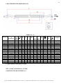
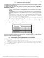
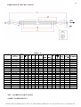
CARATTERISTICHE DIMENSIONALI:
TABELLA “A”
MISURA
”
A
Filettatura
N°
filetti
per
pollice
∅
B
D E F CH
L
min
L
max
L1
g
WFL
kg
FUNE
∅
min
CODICE
3/8 x 6 3/8” UNC 16 9.5 13.5
152 183 17 292 444 94.0 340 540 4.0 081050010
1/2 x 6 1/2 ” UNC 13 11.5 18.0
152 193 19 320 467 100.0
430 1000 5.5 081050011
1/2 x 9 1/2 ” UNC 13 11.5 18.0
229 269 19 408 637 138.5
830 1000 5.5 081050012
5/8 x 9 5/8” UNC 11 13.5 21.5
229 279 24 449 677 143.5
1420 1590 6.0 081050016
5/8 x 12 3/8” UNC 11 13.5 21.5
305 366 24 530 835 192.5
2000 1590 6.0 081050015
3/4 x 6 3/4” UNC 10 16.5 25.5
152 213 30 410 552 110.0
1660 2360 8.0 081050017
3/4 x 9 3/4” UNC 10 16.5 25.5
229 289 30 492 721 149.0
2090 2360 8.0 081050020
3/4 x 12 3/4” UNC 10 16.5 25.5
305 366 30 560 856 187.0
2540 2360 8.0 081050018
3/4 x 18 3/4” UNC 10 16.5 25.5
457 518 30 710 1160 263.0
3200 2360 8.0 081050021
7/8 x 12 7/8” UNC 9 19.5 32.5
305 376 32 592 897 192.5
3670 3270 10.0 081050022
7/8 x 18 7/8” UNC 9 19.5 32.5
457 528 32 754 1211 268.5
4550 3270 10.0 081050023
1 x 6 1” UNC 8 23.5 36.6
152 234 36 507 660 121.0
4230 4540 11.0 081050024
1 x 12 1” UNC 8 23.5 36.6
305 386 36 660 964 198.0
5410 4540 11.0 081050025
1.1/4 x 12 1.1/4” UNC 7 29.5 46.5
305 385 46 719 1024 211.0
8620 6900 14.0 081050031
1.1/4 x 18 1.1/4” UNC 7 29.5 46.5
457 537 46 872 1329 287.0
10400
6900 14.0 081050032
1.1/4 x 24 1.1/4” UNC 7 29.5 46.5
610 689 46 1024 1634 363.5
12300
6900 14.0 081050033
1.1/2 x 12 1.1/2” UNC 6 32.0 54.5
305 401 55 756 1023 222.0
13500
9710 16.0 081050034
1.1/2 x 18 1.1/2” UNC 6 32 54.5
457 553 55 916 1370 298.0
16000
9710 16.0 081050035
1.3/4 x 18 1.3/4” UNC 5 38.0 60.5
457 577 70 1020 1396 295.0
24700
12700
18.0 081050036
Le quote indicate sono espresse in mm.
WFL = FORZA LIMITE DI LAVORO
COEFFICIENTE DI SICUREZZA: 5

4/8
Divisione della BETA UTENSILI SPA, Via Volta, 18 - 20845 SOVICO (MB) ITALY Tel. +39.039.20771-Fax + 39.039.2010742
Definizioni:
• WFL: (working force limit) è la forza massima che l’articolo può sopportare (lungo l’asse principale se
non diversamente indicato) in condizioni di utilizzo.
• Coefficiente di sicurezza: è il rapporto tra la forza di rottura minima garantita e la forza limite di lavoro.
• Ispezione: controllo visivo relativo allo stato del tenditore per individuare evidenti danneggiamenti o
usure che possono alterarne l’utilizzo.
• Esame accurato: esame visivo effettuato da una persona competente e, se necessario, coadiuvato da
altri mezzi, quali i controlli non-distruttivi, al fine di individuare danneggiamenti o usure che possono
alterare l’utilizzo del tenditore.
• Persona competente: persona designata, istruita correttamente, qualificata per conoscenza ed
esperienza pratica, che ha ricevuto le istruzioni necessarie per eseguire le prove e gli esami richiesti.
ATTENZIONE: il coefficiente di sicurezza è soltanto un’indicazione per la sicurezza del prodotto.
Non si devono mai superare le forze (WFL) indicate nella tabella.
2) SPECIFICHE DI COLLAUDO
I singoli elementi che compongono l’articolo sono sottoposti a una serie di severi controlli a campione per
accertarne la funzionalità prestazionale e la rispondenza alle specifiche.
La numerosità del campione e i relativi piani di campionamento sono scelti in funzione della caratteristica
da verificare in accordo e per quanto previsto dalla norma UNI ISO 2859/1, e i risultati archiviati
nell’ufficio qualità dello stabilimento di Sulmona.
2.A Controllo dimensionale
Verifica che le dimensioni dell’articolo rientrino nelle tolleranze stabilite dai relativi
disegni di costruzione interni.
2.B Controllo visivo
Verifica la presenza di eventuali imperfezioni dovute a stampaggio, lavorazione
meccanica, rivestimento superficiale e rispondenza della marcatura a disegni di fase interni.
2.C Analisi chimica
Verifica la rispondenza della composizione chimica del materiale, entro i limiti stabiliti
dalle relative norme.
2.D Prove di trazione
Verifica che l’accessorio sottoposto a una trazione arrivi a rottura, dopo che la forza
applicata abbia almeno superato la forza limite di lavoro moltiplicata per il coefficiente di
sicurezza.
La prova è eseguita in accordo con la norma UNI 10002/1.

5/8
Divisione della BETA UTENSILI SPA, Via Volta, 18 - 20845 SOVICO (MB) ITALY Tel. +39.039.20771-Fax + 39.039.2010742
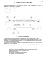
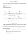
3) COME LEGGERE LA MARCATURA
Sull’accessorio sono stampate in maniera indelebile marcature e sigle che identificano il prodotto e ne
definiscono le caratteristiche e applicazioni.
1) Logo produttore RR (ROBUR)
2) Misura pollici (es. 3/8 x 6)
3) Marchio “CE”
4) Codice di rintracciabilità
5) R (Right) Filettatura destra
6) L (Left) Filettatura sinistra
4) AVVERTENZE GENERALI
Il manuale deve essere custodito da persona responsabile allo scopo preposta, in un luogo idoneo,
affinché esso risulti sempre disponibile per la consultazione nel miglior stato di conservazione. In caso di
smarrimento o deterioramento, la documentazione dovrà essere prontamente sostituita scaricandola dal
sito del costruttore: www.beta-tools.com
Il costruttore si riserva la proprietà materiale ed intellettuale del presente manuale e ne vieta la modifica,
anche parziale, per fini commerciali.
Con riferimento a quanto riportato in queste istruzioni d’uso, la BETA UTENSILI SPA declina ogni
responsabilità in caso di:
• uso degli accessori contrario alle leggi nazionali sulla sicurezza e sull’antinfortunistica;
• errata scelta o predisposizione dell’apparecchio con il quale saranno connessi;
• mancata o errata osservanza delle istruzioni per l’uso;
• modifiche agli accessori;
• uso improprio e omessa manutenzione ordinaria;
• uso combinato ad accessori non conformi.
LATO OPPOSTO

6/8
Divisione della BETA UTENSILI SPA, Via Volta, 18 - 20845 SOVICO (MB) ITALY Tel. +39.039.20771-Fax + 39.039.2010742
!ATTENZIONE: I dati di marcatura non devono essere rimossi con molature o abrasioni, (neanche
accidentali; i tenditori senza riferimenti di identificazione devono essere resi inutilizzabili e
rottamati).
Non è consentito apporre caratteri aggiuntivi a quelli di fabbricazione.
5) CRITERI DI SCELTA
I parametri che devono essere attentamente considerati nella scelta del tenditore sono:
5.A FORZA LIMITE DI LAVORO
La trazione che il tenditore deve esercitare deve essere inferiore o uguale al valore della forza limite di
lavoro (WFL) previsto per l’articolo preso in considerazione, e riportato nella tabella “A”.
5.B ELEMENTO DI ACCOPPIAMENTO
Assicurarsi che l’elemento di collegamento sia adeguato alle caratteristiche di portata del tenditore, abbia
adeguato diametro come da tabella ”A” alla voce “FUNE
ø
min.”, e garantisca una resistenza meccanica
sufficiente alla trazione esercitata dalla presa.
5.C TEMPERATURE D’IMPIEGO
La temperatura d’impiego consentita dovrà essere compresa tra 0°C e +200°C
Al di fuori di questi valori non è più garantita la forza massima di utilizzazione.
6) CONDIZIONI NON AMMESSE
Non è consentito far lavorare i tenditori nei seguenti casi:
• quando la forza applicata è superiore al “WFL” consentito;
• nelle condizioni in cui si possono creare sollecitazioni di tipo dinamico o carichi pulsanti;
• far lavorare i tenditori a temperature diverse da quelle consentite;
• quando la direttrice delle forze non si sviluppa lungo l’asse principale che attraversa i due
terminali.
7) CONTROLLI PRELIMINARI
Prima della messa in servizio e/o del montaggio gli accessori devono essere controllati da una persona
competente adeguatamente addestrata.
• Controllare l’integrità del tenditore e in particolare che non vi siano tagli, piegature,
incisioni, abrasioni, incrinature o cricche, filetti irregolari, corrosioni, bave taglienti,
usure provocate dall’utilizzo o difetti dovuti a cattivo stoccaggio.
• Rilevare e registrare le dimensioni con riferimento alla tabella “A”.
• Controllare l’integrità della marcatura in tutte le sue parti, al fine di identificare con
precisione l’accessorio in funzione della forza di lavoro.
• Verificare la bontà dell’accoppiamento tra i filetti.
8) INSTALLAZIONE - ISTRUZIONI PER IL MONTAGGIO
Durante l’installazione dell’accessorio indossare i dispositivi di protezione adeguati:
guanti, scarpe antinfortunistiche, elmetto, etc.

7/8
Divisione della BETA UTENSILI SPA, Via Volta, 18 - 20845 SOVICO (MB) ITALY Tel. +39.039.20771-Fax + 39.039.2010742
Svitare gli anelli in maniera da ottenere l’apertura massima e collegarli agli elementi da mettere in trazione.
Inserire solo una fune o un solo elemento per ogni terminale.
Esercitare la trazione agendo sul corpo centrale, facendo attenzione che, una volta raggiunta la condizione
di lavoro, gli anelli siano inseriti nel corpo per almeno tutta la lunghezza del filetto di quest’ultimo.
Nell’esercitare la trazione assicurarsi che il tenditore abbia piena libertà di movimento e di
autoposizionamento; non devono quindi mai presentarsi forzature o interferenze che possano generare
componenti di forza laterali.
La condizione della trazione deve essere controllata dopo breve tempo per compensare eventuali
adattamenti del sistema.
Particolare attenzione deve essere posta durante il tensionamento affinché non venga superata la forza limite
di lavoro (WFL, vedi tabella ”A”), per non incorrere in deformazioni permanenti, soprattutto nel caso si
usino leve o mezzi meccanici.
9) USO DELL’ACCESSORIO - PRESA E MANOVRA
Il tenditore è stato concepito per essere utilizzato in situazioni statiche. Controllare periodicamente le
condizioni della trazione, lo stato di conservazione degli elementi e il loro accoppiamento, in riferimento
alla tabella interventi di manutenzione e controllo.
10) CONTROINDICAZIONI D’USO
L’utilizzo dell’accessorio per scopi non previsti, il suo uso in condizioni estremamente pericolose e la
carenza di manutenzione possono comportare gravi situazioni di pericolo per l’incolumità delle persone
esposte e di danno per l’ambiente di lavoro, oltre che pregiudicare la funzionalità e la sicurezza effettiva
del prodotto. Le azioni di seguito citate, che, ovviamente, non possono coprire l’intero arco di potenziali
possibilità di “cattivo uso” dell’accessorio, costituiscono tuttavia quelle “ragionevolmente” più prevedibili.
Quindi:
• NON utilizzare l’accessorio collegandolo ad apparecchiature di dimensioni, temperatura,
punto d’aggancio e forma non idonei alle sue caratteristiche;
• NON utilizzare l’accessorio per il sollevamento diretto;
• NON mettere in tensione apparecchiature che possono cambiare la loro configurazione
statica, il loro baricentro o lo stato chimicofisico;
• NON utilizzare l’accessorio per il sollevamento o il trasporto di persone o animali;
• NON usare l’accessorio per trainare carichi vincolati;
• NON operare in aree dove è prescritto l’uso di componenti antideflagranti/antiscintilla o in
presenza di forti campi magnetici;
• NON saldare sull’accessorio particolari metallici, né intervenire con riporti di saldatura o
utilizzarlo come massa per saldatrici.
11) IDONEITÀ ALL’UTILIZZO
L’accessorio è stato sottoposto a collaudo a campione presso il costruttore per accertare la rispondenza
funzionale e prestazionale dello stesso. L’attestato che accompagna la fornitura certifica il superamento con
esito positivo dei test di collaudo. L’utilizzatore deve eseguire in ogni caso, prima di iniziare a operare, la
verifica della rispondenza funzionale e prestazionale dell’accessorio installato per confermare l’idoneità
all’impiego dell’intera installazione.

8/8
Divisione della BETA UTENSILI SPA, Via Volta, 18 - 20845 SOVICO (MB) ITALY Tel. +39.039.20771-Fax + 39.039.2010742
12) ISPEZIONE E MANUTENZIONE
Comprende una serie di operazioni eseguite da personale competente istruito allo scopo, relative a controlli
ed esami accurati durante l’impiego.
Di seguito l’elenco dei controlli da effettuare con cadenze indicate nella tabella “Interventi di
manutenzione e controllo”.
• VISIVO: verificare l’assenza di difetti superficiali, quali cricche, incisioni, tagli o fessure,
abrasioni.
• CONDIZIONI DEL FILETTO: esaminare lo stato del filetto, che non deve presentare usure,
deformazioni, ammaccature, e l’accoppiamento deve essere preciso, stabile e senza eccessivo
gioco.
• DEFORMAZIONE: verificare che l’accessorio non sia deformato, misurando con un calibro
le dimensioni critiche, come indicato nella tabella “A”. NON sono tollerate deformazioni
rispetto alle quote rilevate alla prima messa in servizio.
• USURA: verificare che i punti di contatto non siano usurati, misurando con un calibro le
dimensioni critiche indicate nella tabella “A”.
• STATO DI CONSERVAZIONE: verificare l’assenza di ossidazione e corrosione soprattutto
in caso di utilizzo all’aperto; verificare l’assenza di cricche con metodi idonei (es. liquidi
penetranti).
Le registrazioni di questi controlli devono essere conservate.
Nel caso in cui il tirante sia sottoposto a un utilizzo gravoso, è necessario effettuare le verifiche di usura e
stato di conservazione con maggiore frequenza.
13) DEMOLIZIONE E ROTTAMAZIONE DELL’ACCESSORIO
L’accessorio deve essere demolito mediante taglio, in modo tale che non possa più essere utilizzato, nel
caso presenti:
- una deformazione permanente rispetto alla misura originale;
- eventuali cricche, distorsioni e/o se si riscontrano riduzioni di sezione rispetto alla misura originale;
- se le condizioni del filetto non garantiscono il perfetto accoppiamento tra le parti, filetti usurati,
deformati, irregolari ecc.
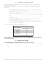
A ogni utilizzo Mese Anno
Controllo visivo gener.
x
Condizioni del filetto
x
Deformazione
x
Usura
x
Stato di conservazione
x
Tabella interventi di manutenzione e controllo
Tipo di controllo

1/8
Division of BETA UTENSILI spa Via Volta. 18 - 20845 SOVICO (MB) ITALY Tel. +39.(0)39.20771-Fax + 39.(0)39.2010742
PRODUCT SPECIFICATIONS
OPERATING AND MAINTENANCE INSTRUCTIONS
Technical Specifications
Operating Conditions and Limits
Operator’s Instructions
Residual Risks
How and how often periodical fitness inspections should be conducted
EYE AND EYE TURNBUCKLE
ITEM 8105
The original language of this technical specification is Italian
Manufacturing site ROBUR wire rope accessories
Zona Industriale – C.da S. Nicola
I-67039 SULMONA (L’AQUILA)
Tel. +39.(0)864.2504.1 – Fax +39.(0)864.253132
www.beta-tools.com – info@roburitaly.com
R/SP/8105/10
Date 22/07/2020

2/8
Division of BETA UTENSILI spa Via Volta. 18 - 20845 SOVICO (MB) ITALY Tel. +39.(0)39.20771-Fax + 39.(0)39.2010742
1) TECHNICAL SPECIFICATIONS
Material / Reference Standard:
BODY steel C45 - UNI EN 10083-2
EYES steel C45 - UNI EN 10083-2
NUT steel strength class 4 - UNI EN 20898-2
Heat Treatment:
BODY normalized - UNI EN 10083-2 (table -10)
EYES hardened and tempered - UNI EN 10083-2 (table -9)
Surface Treatment:
BODY and EYES hot dip galvanized
BODY HEADS orange painted (RAL 2011)
The test is performed on the basis of in-house specifications and rules in accordance with UNI EN ISO
9001.
This item complies with Machinery Directive 2006/42/EC.

3/8
Division of BETA UTENSILI spa Via Volta. 18 - 20845 SOVICO (MB) ITALY Tel. +39.(0)39.20771-Fax + 39.(0)39.2010742
DIMENSIONAL SPECIFICATIONS:
TABLE “A”
SIZE
”
A
Thread
Number
of
threads
per inc.
∅
B
D E F CH
L
min
L
max
L1
g
WFL
kg
ROPE
min
∅
ITEM
NUMBER
3/8 x 6 3/8” UNC 16 9.5 13.5
152 183 17 292 444 94.0 340 540 4.0 081050010
1/2 x 6 1/2 ” UNC 13 11.5
18.0
152 193 19 320 467 100.0
430 1000 5.5 081050011
1/2 x 9 1/2 ” UNC 13 11.5
18.0
229 269 19 408 637 138.5
830 1000 5.5 081050012
5/8 x 9 5/8” UNC 11 13.5
21.5
229 279 24 449 677 143.5
1420 1590 6.0 081050016
5/8 x 12 3/8” UNC 11 13.5
21.5
305 366 24 530 835 192.5
2000 1590 6.0 081050015
3/4 x 6 3/4” UNC 10 16.5
25.5
152 213 30 410 552 110.0
1660 2360 8.0 081050017
3/4 x 9 3/4” UNC 10 16.5
25.5
229 289 30 492 721 149.0
2090 2360 8.0 081050020
3/4 x 12 3/4” UNC 10 16.5
25.5
305 366 30 560 856 187.0
2540 2360 8.0 081050018
3/4 x 18 3/4” UNC 10 16.5
25.5
457 518 30 710 1160 263.0
3200 2360 8.0 081050021
7/8 x 12 7/8” UNC 9 19.5
32.5
305 376 32 592 897 192.5
3670 3270 10.0 081050022
7/8 x 18 7/8” UNC 9 19.5
32.5
457 528 32 754 1211 268.5
4550 3270 10.0 081050023
1 x 6 1” UNC 8 23.5
36.6
152 234 36 507 660 121.0
4230 4540 11.0 081050024
1 x 12 1” UNC 8 23.5
36.6
305 386 36 660 964 198.0
5410 4540 11.0 081050025
1.1/4 x 12 1.1/4” UNC 7 29.5
46.5
305 385 46 719 1024 211.0
8620 6900 14.0 081050031
1.1/4 x 18 1.1/4” UNC 7 29.5
46.5
457 537 46 872 1329 287.0
10400
6900 14.0 081050032
1.1/4 x 24 1.1/4” UNC 7 29.5
46.5
610 689 46 1024
1634 363.5
12300
6900 14.0 081050033
1.1/2 x 12 1.1/2” UNC 6 32.0
54.5
305 401 55 756 1023 222.0
13500
9710 16.0 081050034
1.1/2 x 18 1.1/2” UNC 6 32 54.5
457 553 55 916 1370 298.0
16000
9710 16.0 081050035
1.3/4 x 18 1.3/4” UNC 5 38.0
60.5
457 577 70 1020
1396 295.0
24700
12700
18.0 081050036
All measurements are expressed in mm.
WFL = WORKING FORCE LIMIT
SAFETY COEFFICIENT: 5

4/8
Division of BETA UTENSILI spa Via Volta. 18 - 20845 SOVICO (MB) ITALY Tel. +39.(0)39.20771-Fax + 39.(0)39.2010742
Definitions:
• WFL (working force limit): the maximum force the item can support (along the main axis, if not
otherwise specified) under operating conditions.
• Safety coefficient: guaranteed minimum breaking force to working force limit ratio.
• Inspection: visual testing of the state of the turnbuckle, to check for clear damage or wear which may
affect its use.
• Accurate examination: visual inspection performed by a trained person, supported, if need be, by any
other instruments, including non-destructive testing, to check for damage or wear which may affect the
use of the turnbuckle.
• Trained person: a designated, suitably trained person who has proper know-how and practical
expertise and has been given the instructions needed to perform any required tests and examinations.
CAUTION: The safety coefficient is only provided by way of example, in relation to product safety.
The working force limits (WFL) shown in the table should never be exceeded.
2) TESTING SPECIFICATIONS
The individual parts of the item are subjected to several stringent tests for serviceability, performance and
compliance with specifications.
The number of samples and the related sampling plans are chosen according to the characteristic to test
under UNI ISO 2859/1, and the results are filed in the quality department of the factory in Sulmona.
2.A Dimensional test
Making sure that the dimensions of the item meet such tolerances as established in in-
house working drawings.
2.B Visual test
Testing for defects resulting from forming, mechanical working, surface coating and
correspondence between the marking and in-house drawings.
2.C Chemical analysis
Making sure that the chemical composition of the material complies with the limits
established under the relevant standards.
2.D Tensile stress tests
Making sure that the accessory subjected to tensile stress will break, after the applied
force has at least exceeded the working force limit as multiplied by the safety coefficient.
The test is performed in accordance with UNI 10002/1.

5/8
Division of BETA UTENSILI spa Via Volta. 18 - 20845 SOVICO (MB) ITALY Tel. +39.(0)39.20771-Fax + 39.(0)39.2010742
3) HOW TO READ MARKINGS
:
The accessory carries indelible marks and codes which identify the product and define the specifications
and applications.
1) Manufacturer’s logo RR (ROBUR)
2) Size in inches (e.g. 3/8 x 6)
3) CE mark
4) Traceability code
5) R (Right) Right-handed thread
6) L (Left) Left-handed thread
4) GENERAL WARNINGS
The manual must be kept by the person in charge in a suitable place and readily available for consultation,
in optimal conditions. should it be lost or damaged, the manual can easily be retrieved on the constructor's
web site:
www.beta-tools.com
the constructor detains all material and intellectual rights on the manual, and restricts its modification,
albeit partial, for any commercial use.
As regards the information provided in these operating instructions, BETA UTENSILI S.P.A. will accept
no responsibility in the event of:
• any use of the accessories other than the uses under national safety and accident prevention
laws;
• mistaken choice or arrangement of the apparatus they are going to be connected to;
• failure to comply with, or properly follow, the operating instructions;
• changes to the accessories;
• misuse or failure to carry out routine maintenance jobs;
• use with noncompliant accessories.
REVERSE SIDE

6/8
Division of BETA UTENSILI spa Via Volta. 18 - 20845 SOVICO (MB) ITALY Tel. +39.(0)39.20771-Fax + 39.(0)39.2010742
!CAUTION: The marking data should not be removed by grinding or abrasion (whether
accidental or not – any turnbuckles that do not carry any identification references should be made
unusable and scrapped).
No characters other than the manufacturer’s may be affixed.
5) SELECTION CRITERIA
The following parameters should be carefully considered in choosing the turnbuckle:
5.A WORKING FORCE LIMIT
The tensile stress exerted by the turnbuckle should be lower than or equal to the working force limit
(WFL) recommended for the item being considered, and shown in Table “A”.
5.B CONNECTING PART
Make sure that the connecting part suits the load capacity of the turnbuckle, has a suitable diameter – as
per Table “A”, item “ROPE min.
∅
” - and an adequate mechanical resistance to tensile forces.
5.C OPERATING TEMPERATURES
The permissible operating temperature should range between 0°C and +200°C.
The working force limit will not be guaranteed outside this range.
6) NONPERMISSIBLE CONDITIONS
The turnbuckles should not be operated under the following circumstances:
• when the applied force exceeds the permissible “WFL”;
• when dynamic stresses or swinging loads may result;
• when the turnbuckles are operated under any temperatures other than the permissible
temperatures;
• when the directrix of forces does not develop along the main axis crossing the two
terminals.
7) PRELIMINARY TESTS
Before the accessories are operated and/or assembled, they should be tested by a suitably trained person.
• Check the state of the turnbuckle; in particular make sure that it is free from cuts,
bends, indentations, abrasions, cracks, irregular threads, corrosions, sharp burrs, wear
or defects resulting from improper storage.
• Measure and record the dimensions according to Table “A”.
• Check the state of all the parts of the marking, so that the accessory can be accurately
identified according to the working force.
• Make sure that the threads fit.

7/8
Division of BETA UTENSILI spa Via Volta. 18 - 20845 SOVICO (MB) ITALY Tel. +39.(0)39.20771-Fax + 39.(0)39.2010742
8) INSTALLATION, ASSEMBLY INSTRUCTIONS
During the installation of the accessory please use adequate Personal Protective Equipment: gloves, safety
shoes, helmet, etc.
Unscrew the eyes, so that the maximum available opening can be obtained, and connect them to the parts
to pull.
Insert one rope or one part for each terminal.
Exert tensile stress through the main body, making sure that, after the operating condition has been
reached, the eyes have been inserted into the body at least throughout the length of its thread.
While exerting tensile stress, make sure that the turnbuckle can freely move and position itself; hence no
forcing or interference should occur, to prevent any lateral force components from being produced.
Tensile stress should be checked after a short period, to make up for any system adjustments.
Particular attention is required while tensioning, to prevent the working force limit (WFL, see Table “A”)
from being exceeded, which would result in permanent deformation, especially if any levers or
mechanical means are used.
9) USING ACCESSORY – GRIP AND HANDLING
The turnbuckle is designed to be used in static situations; periodically check tensile stress, the state of
preservation of the parts and their connection, according to the Table “Maintenance jobs and inspections”.
10) NONPERMISSIBILE USE
Using the accessory for any purposes other than the purposes it has been designed for, using it under
extremely dangerous conditions and performing poor maintenance may pose a severe hazard to the
safety of the people being exposed and cause severe damage to the working environment, while
affecting the actual serviceability and safety of the product. The precautions mentioned below, which,
obviously enough, cannot cover the whole spectrum of potential “misuses” of the accessory, should be
“reasonably” deemed to be the most common steps to take. Therefore:
• DO NOT connect the accessory to any apparatus which does not match its specifications in
terms of size, temperature, hook-up point and shape;
• DO NOT use the accessory for direct lifting purposes;
• DO NOT stretch any apparatus that may change its static configuration, centre of gravity or
chemical and physical state;
• DO NOT use the accessory to lift or carry people or animals;
• DO NOT use the accessory to pull restrained loads;
• DO NOT work in areas where any explosion/spark-proof parts are expected to be used or in
the presence of big magnetic fields;
• DO NOT weld any metal parts to the accessory; do not use any filling welds; do not use the
accessory as mass for any welder.
11) FITNESS FOR USE
The accessory was subjected to spot check in order to test serviceability and performance at the
manufacturer’s. The certificate supplied with it states that the tests were passed. However, before starting
working, the user should test the installed accessory for serviceability and performance, to prove the
entire system is fit for use.

8/8
Division of BETA UTENSILI spa Via Volta. 18 - 20845 SOVICO (MB) ITALY Tel. +39.(0)39.20771-Fax + 39.(0)39.2010742
12) INSPECTION AND MAINTENANCE
Inspections and maintenance jobs should be carried out by trained personnel, who should perform
accurate tests during operation.
Below is a list of tests to perform at such intervals as stated in the table “Maintenance jobs and
inspections”.
• VISUAL TEST: making sure that the accessory is free from surface defects, including
cracks, indentations, cuts, fissures and abrasions.
• THREAD TEST: making sure that the thread is free from wear, deformation and dents, that
its fit is accurate and stable, and that there is not too much clearance.
• DEFORMATION TEST: making sure that the accessory has not got deformed, using a
gauge to measure such critical dimensions as shown in Table “A”. NO DEFORMATIONS
will be tolerated compared to the measurements made when the accessory was first put
into operation.
• WEAR TEST: making sure that the points of contact are not worn, using a gauge to
measure such critical dimensions as shown in Table “A”.
• PRESERVATION TEST: making sure that the accessory is free from oxidation and
corrosion, especially in case of outdoor use; using suitable methods (e.g. liquid penetrants)
to make sure that it is free from cracks.
The results of the above-mentioned tests should be stored.
If the turnbuckle has been used for heavy-duty jobs, both wear and the state of preservation should be
tested for more frequently.
13) SCRAPPING ACCESSORY
The accessory should be scrapped by cutting, so that it can no longer be used, if:
- it is permanently worn compared to the original size;
- any cracks or distortions are shown, or the sections have become small compared to the original
size;
- the state of the thread is such that the parts do not fit perfectly, any threads are worn, deformed,
irregular etc.
Whenever used Month Year
General visual inspection
x
Thread state
x
Deformation
x
Wear
x
State of preservation
x
Maintenance jobs and inspections
Type of inspection
-
 1
1
-
 2
2
-
 3
3
-
 4
4
-
 5
5
-
 6
6
-
 7
7
-
 8
8
-
 9
9
-
 10
10
-
 11
11
-
 12
12
-
 13
13
-
 14
14
-
 15
15
-
 16
16


in altre lingue
- English: Beta 8105 Operating instructions
Documenti correlati
-
Beta 8110 Istruzioni per l'uso
-
-
-
-
-
-
-
-
-