
Usage Method
ESC Programmer
Thank you for purchasing an MCP-1 ESC Programmer.
The MCP-1 is a dedicated programmer for the brushless motor ESC given
in “Corresponding ESC” above. Quick and accurate setting matched to
the characteristics of the model is possible and the brushless motor can be
operated at peak performance.
WARNING
When setting and operating
the ESC be sure that no part
of your body touches all the
parts which rotate.
The motor may rotate unexpectedly
due to erroneous connection
and operation of the ESC and is
extremely dangerous.
Before flight, always check
ESC operation.
If the ESC is not set properly
control will be lost and is extremely
dangerous.
CAUTION
Do not open the case or
disassemble this product.
The interior will be damaged.
In addition, repair will become
impossible.
This product is only for use with
the “Corresponding ESC” shown
above. It cannot be used with
other products.
Set the ESC parameters as follows:
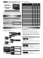
Programmer connection
Connect the MCP-1 and drive battery to the ESC.
Connect the MCP-1.
To Programmer
Edit buttons operation
LCD
Edit buttons
Setting
item
selection
Select the setting items with
the left and right outside
arrow buttons (
È
or
Ç
).
Setting
contents
change
The inside INC(+) and
DEC(-) buttons are used
to select and change the
setting contents.
Model
type
change
The model type can be
changed by pressing
both arrow buttons
simultaneously.
Setting method
When the MCP-1 and drive battery are connected to the ESC, the current
setting contents of the ESC are automatically read to the MCP-1.
Select the item you want to change with the arrow buttons ĻorĹ and
change the setting contents with the ,1C and 'EC- buttons.
[IMPORTANT] At the end of ESC parameters setting with the MCP-
1, write the setting data to the ESC with the (17) “Writing setting
data to ESC” function. The setting data is not written to the ESC by
only setting the parameters.
(1) Battery type selection
Setting range: LiPo, NiCd
Initial setting: LiPo
Select the type of drive battery used by means of the DEC(-) or
INC(+) button.
* When the battery type changes, the “CUT OFF VOLTAGE” and “CUT OFF
TYPE” parameters change.
(2) Cut off voltage setting
Setting range: Auto (automatic setting), 4.5~50V
Initial setting: Auto
Set the cut off voltage to match the type of battery used. Adjust
the voltage with the DEC(-) or INC(+) button.
* At auto mode Auto setting, when the battery type is LiPo, power to the motor
is cut off at 3V per cell. For NiCd, power to the motor is cut off when the total
voltage is 12V.
(3) Cut off type selection
Setting range: Soft off (soft), Hard off (hard)
Initial setting: Soft off
The cut off method when the battery voltage drops to the set cut
off voltage can be selected.
MCP-1 setting items
*The setting items for each model type are shown in the table below.
Setting item
Model type
AIR HELI BOAT/CAR
(1) Battery type selection
Okay Okay Okay
(2) Cut off voltage setting
Okay Okay Okay
(3) Cut off type selection
Okay Okay Okay
(4) Motor direction selection
Okay Okay Okay
(5) Advance timing setting
Okay Okay Okay
(6) Acceleration setting
Okay Okay Okay
(7) Start power setting
Okay Okay Okay
(8) Air brake function type selection (AIR only)
Okay --- ---
(9) Air brake function ON/OFF (AIR only)
Okay --- ---
(10) Reverse function selection (BOAT/CAR only)
--- --- Okay
(11) Governor function response setting (HELI only)
--- Okay ---
(12) Governor function ON/OFF (HELI only)
--- Okay ---
(13) Motor poles number setting
Okay Okay Okay
(14) Gear ratio setting
Okay Okay Okay
(15) Maximum speed display
Okay Okay Okay
(16) Average speed display
Okay Okay Okay
(17) Writing setting data to ESC
Okay Okay Okay
(18) Reading setting data saved at MCP-1
Okay Okay Okay
(19) Saving setting data to MCP-1
Okay Okay Okay
1M23N25408
NOTE: Always read this manual before using
the MPC-1 ESC Programmer.
Corresponding ESC: MC9100A, MC970A, MC951H/A
Usage precautions

(4) Motor direction selection
Setting range: Normal (forward rotation), Reverse
(reverse rotation)
Initial setting: Normal
The direction of motor rotation is selected here.
* When the direction of rotation is reversed, change the mode.
* The direction of rotation can also be changed by changing the motor wiring.
(5) Advance timing setting
Setting range: 0~25°
Initial setting: 14° (for FMA-50xx Series)
As a setting standard, for an ordinary 2-pole inner rotor motor, a
setting of 0~5° is recommended.
When setting to match the motor used, set within the following
range:
Setting example: 0~10° (inner rotor), 14~25° (outer rotor)
* For the FMA-50xx Series, 14° is recommended.
(6) Acceleration setting
Setting range: Lowest/Low/Normal/High/Highest
(Slow)
ÅÆ
(Fast)
Initial setting: Normal
The speed of rise until the ESC reaches maximum speed can be
set here. (Delay function) Select the acceleration with the DEC(-)
or INC(+) button.
This function is mainly set when turning the ESC on and off by
switch.
(7) Start power setting
Setting range: Lowest/Low/Normal/High/Highest
(Low power)
ÅÆ
(High power)
Initial setting: Normal
The power (torque) level at motor starting can be set here.
* To avoid rapid and drastic gear wear when using a helicopter, setting the start
power to a low level is recommended.
(8) Air brake function type selection (AIR mode only)
Setting range: Slow/Normal/Fast/value 5~100%
(Slow)
ÅÆ
(Fast)
Initial setting: Normal
When the model type is AIR, the air brake effect can be adjusted.
Whether the motor stops gradually or stops immediately can be
selected. Select with the DEC(-) or INC(+) button.
* 100% is immediate stop.
(9) Air brake function ON/OFF (AIR mode only)
Setting range: On/Off
Initial setting: Off
Air brake ON/OFF can be selected here.
(10) Reverse function selection (BOAT/CAR modes
only)
Setting range: One Way/Two Way
(forward only)/(forward & reverse)
Initial setting: One Way
When the model type is BOAT or CAR, forward only or forward/
reverse operation can be selected.
Note:When making this change, set each point +ighNeutral5everse in
accordance with the throttle position setting method of the ESC instruction
manual. Other setting contents may also change. Check the setting contents.
(11) Governor function response setting (HELI mode
only)
Setting range: Slowest/Slow/Normal/Fast/Fastest
(Slow)
ÅÆ
(Fast)
Initial setting: Fastest
The governor operation response characteristic can be set.
Note: When a fast value is selected, the current consumption of the battery will
increase.
* To prevent shortening of the life of the ESC and drive battery, setting to Slow is
recommended.
(12) Governor function ON/OFF (HELI mode only)
Setting range: On/Off
Initial value: On
The governor function is switched ON and OFF.
* The governor function maintains the speed corresponding to the throttle
operation position throttle curve even when the load is changed by pitch
operation and the voltage of the drive battery changes. However, the battery
current consumption also becomes large.
(13) Motor poles number setting
Setting range: 2~36 poles
Initial value: 14 (For FMA-50xx Series)
Change the number of poles to match the motor used.
* This setting is necessary to display the actual speed.
(14) Gear ratio setting
Setting range: 1.0:1 ~ 25.0:1
Initial value: 1.0:1
Inputs the gear ratio of the gearbox used.
* The speed display value is calculated from the number of motor poles and the
gear ratio of the gearbox.
(15) Maximum speed display
Displays the maximum speed directly before flight.
* The speed display value is calculated from the number of motor poles and the
gear ratio of the gearbox. The initial value records the factory test value. The
maximum speed display value changes when the motor speed changes.
(16) Average speed display
Displays the average speed directly before flight.
* The speed display value is calculated from the number of motor poles and the
gear ratio of the gearbox. The initial value records the factory test value. The
average speed display changes when the motor speed changes.
(17) Writing setting data to ESC
Execute when writing (transferring) the set values to the ESC.
Start writing by pressing the INC(+) button.
* A beep sounds every second until writing is complete. If you want to abort the
procedure, press the 'EC- button.
(18) Reading setting data saved at programmer
Execute to read the setting data saved at the programmer
memory. Start reading by pressing the INC(+) button.
* A beep sounds every second until reading is complete. If you want to abort the
procedure, press the 'EC- button.
(19) Saving setting data to programmer memory
Execute to save the setting data to the programmer memory. Start
backup by pressing the INC(+) button.
* A beep sounds every second until backup is complete. If you want to abort the
procedure, press the 'EC- button.
FUTABA CORPORATION Phone: +81 475 32 6982, Facsimile: +81 475 32 6983
1080 Yabutsuka, Chosei-mura, Chosei-gun, Chiba 299-4395, Japan
©FUTABA CORPORATION 2011, 10 (1)
-
 1
1
-
 2
2


in altre lingue
- English: Futaba MCP-1 User manual
Documenti correlati
Altri documenti
-
Franke FMA 2.0 607 Manuale utente
-
Lexmark X500n MFP 7100-XXX Manuale utente
-
Lexmark 7100 Series Manuale utente
-
-
Lexmark 4300 Manuale utente
-
Lexmark X125 Manuale utente
-
-
-
High End Systems Powerline Fixtures Guida utente
-