Baxi 3-Way Valve 1 Inch 1/4 For Domestic Hot Water Manuale utente
- Tipo
- Manuale utente

en
VALVOLA DEVIATRICE A 3 VIE
DA 1”1/4 PER ACS
Manuale istruzioni
Operating and installation instructions
3-WAY VALVE 1"1/4 FOR DOMESTIC HOT WATER

1
Questi apparecchi sono stati realizzati per il raffreddamento e/o il
riscaldamento d’acqua e dovranno essere destinati a questo uso com-
patibilmente con le loro caratteristiche prestazionali, questi apparecchi
sono progettati per l’uso residenziale o similare.
È esclusa qualsiasi responsabilità contrattuale ed extracontrattuale
dell’Azienda per danni causati a persone, animali o cose, da errori di
installazione, di regolazione e di manutenzione o da usi impropri. Tutti
gli usi non espressamente indicati in questo elenco non sono consentiti.
Leggere attentamente il presente fascicolo; l’esecuzione di tutti i
lavori deve essere effettuata da personale qualificato, secondo le nor-
me vigenti in materia nei diversi paesi.
La validità della garanzia decade nel caso non siano rispettate le indi-
cazioni sopra menzionate e se, all’atto della messa in funzione dell’u-
nità, non sia presente il personale autorizzato dall’Azienda (ove previsto
nel contratto di fornitura) che dovrà redigere un verbale di avviamento.
La documentazione fornita con l’unità deve essere consegnata al
proprietario affinché la conservi con cura per eventuali future manuten-
zioni o assistenze.
Gli interventi di riparazione o manutenzione devono essere eseguiti dal
Servizio Tecnico di Assistenza dell’Azienda o da personale qualificato
secondo quanto previsto dal seguente libretto.
AVVERTENZE GENERALI
La presente pubblicazione è di esclusiva proprietà del produttore la
quale pone il divieto assoluto di riproduzione e divulgazione della stes-
sa se non espressamente autorizzata per iscritto dal produttore.
Questo documento è stato redatto con la massima cura ed attenzione
ai contenuti esposti, il produttore non può assumersi tuttavia alcuna
responsabilità derivante dall'utilizzo della stessa.
DECLINAZIONE DI RESPONSABILITÀ
This publication is the sole property of the manufacturer. Any repro-
duction or disclosure of such is strictly prohibited without
the written authorisation of the manufacturer.
This document has been prepared with maximum care and attention
paid to the content shown. Nonetheless, manufacturer waives all liabil-
ity deriving from the use of such document.
WAIVER OF LIABILITY
Ricordiamo che l’utilizzo di prodotti che impiegano energia elettrica ed
acqua, comporta l’osservanza di alcune regole fondamentali di sicurez-
za quali:
È vietato l’uso dell’apparecchio ai bambini e alle persone inabili non
assistite.
È vietato toccare l’apparecchio se si è a piedi nudi e con parti del cor-
po bagnate o umide.
È vietata qualsiasi operazione di pulizia, prima di aver scollegato il
dispositivo dalla rete di alimentazione elettrica.
È vietato modificare i dispositivi di sicurezza o di regolazione senza
l’autorizzazione e le indicazioni del costruttore dell’apparecchio.
È vietato tirare, staccare, torcere i cavi elettrici fuoriuscenti dall’appa-
recchio, anche se questo è scollegato dalla rete di alimentazione elettri-
ca.
È vietato aprire gli sportelli di accesso alle parti interne dell’apparec-
chio, senza aver prima posizionato l’interruttore QF1 su OFF (vedi
schema elettrico).
È vietato disperdere, abbandonare o lasciare alla portata di bambini il
materiale dell’imballo (cartone, graffe, sacchetti di plastica, ecc.) in
quanto può essere potenziale fonte di pericolo.
Alimentazione: i cavi elettrici devono essere di sezione adeguata alla
potenza della unità ed i valori di tensione di alimentazione devono corri-
spondere a quelli indicati per le rispettive macchine; tutte le macchine
devono essere collegate a terra come da normativa vigente nei diversi
paesi.
Collegamento idraulico da eseguire come da istruzioni al fine di
garantire il corretto funzionamento dell’unità.
When operating equipment involving the use of electricity and water, a
number of fundamental safety rules must be observed, namely:
The unit must not be used by children or by unfit persons without suit-
able supervision.
Do not touch the unit with bare feet or with wet or damp parts of the
body.
Never perform any cleaning operations before having disconnected
the unit from the mains power supply.
Do not modify safety or control devices without authorisation and
instructions from the manufacturer.
Do not pull, detach or twist the electrical cables coming from the unit,
even when disconnected from the mains electricity supply.
Do not open doors or panels providing access to the internal parts of
the unit without first ensuring that the switch QF1 is in the OFF position
(see the wiring diagram).
Do not dispose of, abandon or leave within reach of children packag-
ing materials (cardboard, staples, plastic bags, etc.) as they may repre-
sent a hazard.
Power supply: the cross section of the electrical cables must be ade-
quate for the power of the unit and the power supply voltage must cor-
respond with the value indicated on the respective units. All units must
be earthed in conformity with legislation in force in the country con-
cerned.
Water connections should be carried out as indicated in the instruc-
tions to guarantee correct operation of the unit.
REGOLE FONDAMENTALI DI SICUREZZA FUNDAMENTAL SAFETY RULES
IT GENERAL WARNING
These appliances have been designed to chill and/or heat water and
must be used in applications compatible with their performance charac-
teristics; these appliances are designed for residential or similar appli-
cations.
Incorrect installation, regulation and maintenance or improper use
absolve the manufacturer from all liability, whether contractual or other-
wise, for damage to people, animals or things.
Only those applications specifically indicated in this list are permitted
Read this manual carefully. All work must be carried out by qualified
personnel in conformity with legislation in force in the country con-
cerned.
The warranty is void if the above instructions are not respected and if
the unit is started up for the first time without the presence of personnel
authorised by the Company (where specified in the supply contract)
who should draw up a “start-up” report.
The documents supplied with the unit must be consigned to the own-
er who should keep them carefully for future consultation in the event of
maintenance or service.
All repair or maintenance work must be carried out by the Company’s
Technical Service or qualified personnel following the instructions in this
manual.
VALVOLA DEVIATRICE A 3 VIE DA 1”1/4 PER ACS
3-WAY VALVE 1"1/4 FOR DOMESTIC HOT WATER
EN
IT
EN

2
Al momento della consegna della merce da parte del trasportatore,
verificare l’integrità degli imballi e delle unità. Se si dovessero accertare
danni o assenza di componenti, indicarlo sulla bolla di consegna e tra-
mite fax o raccomandata inoltrare entro 8 giorni dalla data di ricevimen-
to merce un reclamo formale al Servizio Post Vendita.
È vietato disperdere nell’ambiente le parti dell’imballo, o lasciarle alla
portata dei bambini in quanto potenziale fonte di pericolo. Attenersi alle
normative locali vigenti per lo smaltimento dell'imballo tramite i centri di
raccolta o riciclaggio specializzati.
Vengono impiegate per la regolazione di acqua calda verso un accumu-
lo sanitario.
Are used for the regulation of hot water to an domestic hot water tank.
RICEVIMENTO PRODOTTO
When the items are consigned by the carrier, check that the packag-
ing and the unit are undamaged.
If damage or missing components are noted, indicate this on the deliv-
ery note. A formal complaint should be sent via fax
or registered post to the After Sales Department within eight days from
the date of receipt of the items.
Do not dispose of packaging materials in the environment or leave
them within reach of children as they may represent a hazard.
RECEIVING THE PRODUCT
COMPONENTI DEL KIT CONTENT OF THE KIT
IMPIEGO USE
N°1 Servocomando ON/OFF 230VAC
N°1 Corpo valvola 3 vie G 1”1/4 maschio
N°2 Dadi M6
N°1 Kit prolunga
N°1 Foglio di istruzione
Nr. 1 230VAC ON/OFF servo control
Nr. 1 3-way valve body G 1”1/4 male
Nr. 2 M6 nuts
Nr. 1 Extension kit
Nr. 1 Instruction sheet
DATI TECNICI
Valve body
Operating pressure
Leaks
Fluid temperature
Angle of rotation
Thread
Valve body and fitting
Stem
Gasket
Ball
Weight
Servomotor
Power supply
Frequency
Power consumption
Travel time (open/close)
Free auxiliary contact
(end travel)
Allowable operating
temperature
Allowable transport and storage
temperature
Allowable humidity
Index of protection
Connection cable
Manual control
Weight
PN16 for water at 90°C.
PN20 for chilled water
None
Water 0°C to 90°C
90°
Gas UNI ISO 228
Brass OT58, UNI575/65
Brass
PTFE seat, EPDM O-ring
Chrome-plated brass
1.28 kg
230VAC, +10% - 15%
50Hz
4 VA
10 s
230V - 1A (resistive)
0 to + 50 °C
- 10 to + 80 °C
Class G, DIN 40040
IP 54
6 x1 mm2, 0.8 m long
manual open/close control
0.45 kg
Corpo valvola
Pressione d’esercizio
Trafilamento
Temperatura fluido
Angolo di rotazione
Filettatura
Corpo valvola e manicotto
Stelo
Guarnizione di tenuta
Sfera
Peso
Servomotore
Alimentazione
Frequenza
Consumo
Tempo di corsa (aperto/chiuso)
Contatto libero ausiliario
(fine corsa)
Temperatura ambiente ammessa
di funzionamento
Temperatura ambiente ammessa
di trasporto e magazzino
Umidità ambiente ammessa
Grado di protezione
Cavo di collegamento
Comando manuale
Peso
PN16 per acqua a 90°C.
PN20 per acqua refrigerata
Nullo
Acqua 0°C...90°C
90°
Gas UNI ISO 228
Ottone OT58, UNI575/65
Ottone
anello sede in P.T.F.E O-ring in EPDM
Ottone cromato
1,28 Kg
230VAC, +10% - 15%
50Hz
4 VA
10s
230V - 1A (resistivi)
0 ... + 50 °C
- 10 ... + 80 °C
Class G, DIN 40040
IP 54
6 x1 mm2, lunghezza 0,8m
comando manuale apertura/chiusura
0,45 Kg
TECHNICAL SPECIFICATIONS
IT EN

3
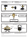
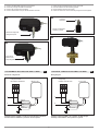
Per il corretto montaggio della valvola è ammessa qualsiasi posizione
tranne quella con il servomotore rivolto verso il basso.
For correct assembly of the valve, any position is allowed except for the
servomotor facing downwards.
Le valvole a 3 vie devono sempre essere impiegate come deviatrici sul-
la mandata, vedere anche “schemi di utilizzo” del manuale di installazio-
ne della pompa di calore.
The 3-way valves must always be used as selector valves on the
outlet, also see “operating diagrams” in the heat pump installation manu-
al.
INSTALLAZIONE CORPO
VALVOLA E SERVOMOTORE
VALVE BODY AND
SERVOMOTOR INSTALLATION
SI - YES SI - YES NO - NO
Impianto
System
OUT OUT
Accumulo sanitario
DHW storage
Mandata pompa di calore
Heat pump outlet
IT EN
IN
La tacca di riferimento presente sullo stelo della valvola deve essere
posizionata sempre verso l’accumulo sanitario (ACS).
The reference notch on the stem of the valve always must be facing
towards the DHW storage cylinder.
Nel caso di errato funzionamento bisogna riposizionare la sfera. Per farlo
smontare il servomotore e ruotare a mano la sfera di 180°.
Il servocomando è dotato di comando manuale.
Premere il pulsante e ruotare la manopola per aprire o chiudere manual-
mente la valvola.
In the event of malfunctions, reposition the ball.
To do this, remove the servo motor and turn the ball 180° by hand.
The servo control features manual control.
Press the button and turn the knob to open or close the valve manually.
Impianto
System
Accumulo sanitario
DHW storage
Ballon sanitaire
Tacca di riferimento
Reference notch
Pulsante Comando Manuale
Manual control button
Manopola Comando Manuale
Manual control knob
CLOSE
Lato Impianto
System
OPEN
Accumulo Sanitario
DHW storage
AAB

1 2
3
4
4
1. Fissare i due distanziali esagonali al servomotore.
2. Inserire la prolunga nel cilindro di isolamento.
3. Inserire il kit prolunga nel servomotore.
4. Fissare il servomotore al corpo valvola tramite le viti fornite.
1. Fasten the two hexagonal spacers to the servomotor.
2. Place the extension in the insulating cylinder.
3. Fit the extension kit to the servomotor.
4. Fasten the servomotor to the valve body using the screws supplied.
Distanziale esagonale
Hexagonal spacer
Kit prolunga
Extension kit
Kit prolongateur
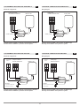
margaid gniriWotnemagelloc id amehcS
Contatto ausiliario CHIUSO = posizione valvola Accumulo Sanitario
Contatto ausiliario APERTO = posizione valvola Impianto
Auxiliary contact CLOSED = valve position to DHW storage
Auxiliary contact OPEN = valve position to system
COLLEGAMENTO ELETTRICO PER PBM2-i e PBMC-i ELECTRICAL CONNECTION FOR PBM2-i and PBMC-i
IT EN
Prolunga
Extension
Cilindro di isolamento
Insulating cylinder
AO AC
Giallo/Verde
Rosso
Blu
N
F
Verde
Nero
Marrone
Valvola 3 vie
Pompa di Calore
Morsettiera Installatore
Contatto Ausiliario
Yellow/Green
Red
Blue
Green
Black
Brown
A
uxiliary contact
3-way valve
Heat pump
Installer terminal block
AO1 AO AC AO1
N
F

Wiring diagramSchema di collegamento
Contatto ausiliario CHIUSO = posizione valvola Accumulo Sanitario
Contatto ausiliario APERTO = posizione valvola Impianto
Auxiliary contact CLOSED = valve position to DHW storage
Auxiliary contact OPEN = valve position to system
COLLEGAMENTO ELETTRICO PER AURIGA M/T-A ELECTRICAL CONNECTION FOR AURIGA M/T-A
IT EN
5 15
Giallo/Verde
Rosso
Blu
Verde
Nero
Marrone
Valvola 3 vie
Pompa di Calore
Morsettiera Installatore
Contatto Ausiliario
Yellow/Green
Red
Blue
Green
Black
Brown
Auxiliary contact
3-way valve
Heat pump
Installer terminal block
18 5 15 18
Wiring diagramSchema di collegamento
Contatto ausiliario CHIUSO = posizione valvola Accumulo Sanitario
Contatto ausiliario APERTO = posizione valvola Impianto
Auxiliary contact CLOSED = valve position to DHW storage
Auxiliary contact OPEN = valve position to system
COLLEGAMENTO ELETTRICO PER PBS-I WH2 ELECTRICAL CONNECTION FOR PBS-I WH2
IT EN
L2L1
Giallo/Verde
Rosso
Blu
Verde
Nero
Marrone
Valvola 3 vie
Pompa di Calore
Scheda elettronica
Alimentazione External
Power
esterna
Attenzione:
va prevista la stessa fase
Attention:
the phase must be the same
as heat pump
della pompa di calore
Contatto Ausiliario
Yellow/Green
Red
Blue
Green
Black
Brown
Auxiliary contact
3-way valve
Heat pump
Electronic board
NL1 L2 N
N F N P

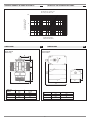
6
Portata acqua (l/sec)
Water flow-rate (l/sec)
Kvs Valvola a 3 vie DN 1-1/4”
Kvs 3-way valve DN 1-1/4"
0,1
1
10
100
110100
Perdite di carico (KPa)
Pressure drop (KPa)
GRAFICO PERDITE DI CARICO VALVOLA GRAPH OF VALVE PRESSURE DROPIT EN
L
S
BH
LP
H
L1
DIMENSIONI
Corpo valvola
Valve body
Servocomando
Servo control
DIMENSIONS
Attacchi
Fittings
inch 1”1/4 G
Lmm 102,6
Bmm 76,8
Hmm 51,3
Smm 39,8
Lmm 131
L1 mm 156
Hmm 75
Pmm 70
IT EN

-
 1
1
-
 2
2
-
 3
3
-
 4
4
-
 5
5
-
 6
6
-
 7
7
-
 8
8


Baxi 3-Way Valve 1 Inch 1/4 For Domestic Hot Water Manuale utente
- Tipo
- Manuale utente
in altre lingue
Altri documenti
-
BALTUR TBL 510 ME 50Hz Use and Maintenance Manual
-
 Biasi ADAPTA TOWER 107/114 Guida d'installazione
-
-
-
-
-
-
-
