
Multiband ampliers MA074T, MA074TM, MA075T, MA076T, MA077TB EN
Vers. 1.10 1
IT
EN
Caution.
Risk of electric shock.
This product complies with the relevant clauses of the European Directive 2002/96/EC. The unit must be recycled or discarded
according to applicable local and national regulations.
ThedevicehasintegratedLTElter.
Equipment intended for indoor usage only.
Equipment is double insulated from the mains, with functional earthing.
Functional earthing. Connect to the main potential equalization.
This product is in accordance to following norms of EU: EMC norm EN50083-2, safety norm EN IEC62368-1 and RoHS norm EN50581.
This product is in accordance with Custom Union Technical Regulations: “Electromagnetic compatibility of technical equipment“
CU TR 020/2011, “On safety of low-voltage equipment“ CU TR 004/2011.
This product is in accordance with safety standard AS/NZS 60065 and EMC standards of Australia.
Product description
Multiband ampliers are intended to amplify FM radio signals, TV signals in VHF (5-12 channels), UHF/BIV+BV
(21-48 channels), UHF1/BIV (21-35 or 21-32 channels), UHF2/BV (36-48 or 34-48 channels). See the “Technical
characteristics” table for details.
Thereisapossibilitytoadjustthegainoftheamplierineverysub-bandbyneturning10dBregulators[7] and an
additional 10 dB by switching switches [8] in every sub-band.
Theamplierhaspossibilitytofeedexternalequipmentonlythroughinputconnector[3]viaon/oswitch[11]. Feeding for
externalequipmentisshortcircuitandoverloadprotected.Ifcurrentusedbyexternalequipmentisupto0.1A,anindicator[6]
glows green. When current increases, the protection circuit starts to operate and the voltage supply has being disconnected
fromexternalequipment.Inthiscasetheindicatorglowsred(overloaded).
The housing of ampliers meets more stringent screening requirements according to EN50083-2, class A.
AccordingtothestandardETSIEN303354V.1.1.1,thisampliertypeisLaunch,selectivityclasication0.
Theamplierisintendedforindooruseonly.
Safety instructions
InstallationoftheampliermustbedoneaccordingIEC60728-11 and national safety standards.
Theampliersarepoweredfrommains230V~.Thisvoltageisdangeroustolife.
Any repairs must be done by a skilled personnel.
Theamplierisdoubleisolatedfromthemains230V~.
To avoid the electric shock follow these instructions:
Do not remove the cover of the power supply section, without disconnecting the unit from the mains supply.
Donotplugtheamplierintothemainssupplyifthepowercordorplugisdamaged.
Donotplugtheamplierintothemainssupplyuntilallcableshavebeenconnectedcorrectly.
The mains socket must be easily accessible.
Theampliershallnotbeexposedtodrippingorsplashingwater.
Avoidplacingampliernexttocentralheatingcomponents,nearhighlycombustiblematerialsandinareasofhighhumidity.
Iftheamplierhasbeenkeptincoldconditionsforalongtime,keepitinawarmroomnolessthan2hoursbeforeplugging
into the mains.
Do not insert any objects into ventilation openings.
The ventilation should not be impeded by covering the ventilation openings with items, such as newspapers, table-cloths,
curtains.
MounttheamplierinverticalpositionwithRFinputconnectorsunderneath.Theampliermustbexedwithsteelscrews
Ø 4-5 mm. The screws are not included in a package. Shields of cables must be connected to main potential equalization bus.
Fromtop,frontandbottomofinstalledampliermustbeatleast10cmfreespace.

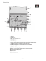
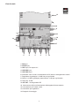
External view
2
13
6
9
10
8
7
7
8
11
12
3 2 15 4
14
14
1. FM input
2. VHFIII input
3. UHFinput,DCoutput12V
4. UHF2/BV input
5. UHF1/BIV input
6.InternalDCandexternalequipmentshortcircuitandoverloadindicator
7.10dBnetuninggainregulatorsforeachsub-band
8. 10 dB gain switches (10 dB attenuation for each sub-band)
9. Test point -30 dB
10. RF OUT - RF signal output
11.Switchtoturnon/othepowerfeedforexternalequipment
12. Functional grounding clamp
13. Screwdriver
14. Mounting supports

Draugystesstr.22,LT-51256Kaunas,Lithuania,tel.:+37037
-
313444,fax:+37037
-
31 35 55
E-mail: [email protected], http://www.terraelectronics.com
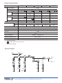
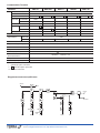
Technical characteristics
* both inputs are filtered
** LTE signal suppression filter on the input
*** with external DC loading
Structure diagram
DC
S S
UHF 1 UHF 2 UHF VHFIII FM
DC
230 V~
test -30 dB
RF OUT
LTE LTE
Type MA074T MA074TM MA075T MA076T MA077TB
Gain FM (88-108 MHz) 35 dB
VHFIII (174-230 MHz) 35 dB
UHF (470-694 MHz)** 44 dB 44 dB 47 dB 2x47 dB* 44 dB
UHF1/BIV (470-590 MHz) 44 dB - - - -
(470-566 MHz) - 44 dB - - -
UHF1 (470-862 MHz) - - - - 44 dB
UHF2/BV (590-694 MHz)** 44 dB - - - -
(574-694 MHz)** - 44 dB - - -
UHF2 (470-678 MHz) - - - - 44 dB
Number of inputs 5 5 3 4 5
Noise figure, typical VHF < 5 dB
UHF < 4 dB < 4 dB < 3 dB < 3.5 dB < 4 dB
Maximal output level IMD3=60 dB (DIN45004B) 121 dBµV, IMD3=60 dB 118 dBµV
Gain control 0 ÷ - 20 dB
Return loss > 10 dB
Test point - 30 dB
DC feeding for external 12 V 100 mA max.
Supply voltage limit values, 198-250 V~ 50/60 Hz 7 W
power consumption***
Operating temperature range -20 oC ÷ +50 oC
Dimensions/Weight (packed) 135x180x52 mm/0.72 kg

Amplicatori multibanda MA074T, MA074TM, MA075T, MA076T, MA077TB IT
Vers. 1.10 1
Attenzione.
Rischio scosse elettriche.
QuestoprodottoèconformeallespecicherilevantidelladirettivaEuropea2002/96/EC.Ilprodottodeveesserericiclatoosmaltito
secondolaleggeeleprocedureapplicatenellaproprianazioneinmaterialdiriutielettronici.
IldispositivopossiedeunltroLTEintegrato.
Prodotto per uso esclusivo interno (indoor).
Apparecchio con doppio isolamento elettrico, con messa a terra funzionale.
Massa. Collegare a una barra equipotenziale.
Che questo prodotto è conforme alle normative europee EU: EMC EN50083-2 e alle normative di sicurezza EN IEC62368-1, RoHS EN50581.
Che questo prodotto è conforme alle Normative Tecniche Armonizzate “Compatibilità Elettromagnetica per apparecchiature elettriche”
CU TR 020/2011 e “Sicurezza per apparecchiature a bassa tensione” CU TR 004/2011.
Che questo prodotto è conforme alla norma di sicurezza AS/NZS 60065 e EMC standard dell’Australia.
Descrizione Prodotto
Centralino Multibanda per la miscelazione e amplicazione di segnali TV e Radio nelle bande VHF (ch 5-12),
UHF(ch21-48),UHF-B.IV(ch21-34o21-32)eUHF-B.V(ch36-48o34-48).Vericarenellatabella“CaratteristicheTecniche”
idettaglidibandapassanteperognimodello.Ognisingolabandaamplicatahaunaregolazioneindipendentedelguadagno
di 10 dB [7] e uno switch aggiuntivo con ulteriore step di 10 dB di guadagno [8].
L’amplicatore può fornire alimentazione (+12 V) ad apparecchiature esterne attraverso uno degli ingressi UHF [3].
Questa alimentazione è accesa/spenta tramite un apposito switch [11]. L’alimentazione verso apparecchiature esterne è
dotata di protezione da corto circuiti e sovratensioni.
Se la corrente assorbita è inferiore a 0.1 A l’indicatore [6] è acceso e verde. Se la corrente assorbita aumenta, il circuito
di protezione entra in azione e la tensione verso l’apparecchiatura esterna viene interrotta. In questo caso il led sarà rosso
(sovraccarico).
SecondolanormaETSIEN303354V.1.1.1,questotipodiamplicatoreèLaunch,classicazioneselettività0.
QuestoamplicatorevieneprodottosoloperinstallazioneinINTERNO.
Prescrizioni di sicurezza
L‘installazionedegliamplicatorideveessereeettuatainconformitàaglistandardIEC60728-11edisicurezzanazionali.
L‘amplicatoreèalimentatodalleretea230V~.Questatensioneèpericolosaperlavita.
Qualsiasiriparazionedeveessereeettuatadapersonalequalicato.
L‘amplicatoredoppiamenteisolatodallareteelettricaa230V~.
Non rimuovere il coperchio della sezione di alimentazione senza aver scollegare il prodotto dalla rete elettrica.
Noncollegarel‘amplicatoreallapresaelettricaseilcavodialimentazioneèdanneggiato.
Noncollegarel‘amplicatoreallapresaelettricanoachenonsonostaticollegatituttiicavicorrettamente.
La presa elettrica deve essere facilmente accessibile.
L‘alimentatore non deve essere esposto all‘azione di acqua o vapore.
Evitare di posizionare vicino a componenti di centrali di riscaldamento, nei pressi di materiali altamente combustibile o
in aree ad alto tasso di umidità.
Tutti gli apparecchi dovranno avere facile accesso per poterli scollegare dall‘alimentazione.
Sel‘amplicatoreèstatotenutoalungoalfreddo,tenerloperalmeno2oreinambientepiùcaldoprimadialimentarlo.
Non introdurre alcun oggetto nelle aperture per la ventilazione.
Laventilazionedovrebbeesserenonostruita,evitareperciòdicoprirelepresed‘aria.
MontareinposizioneverticaleconiconnettoriRFcomeingura.L‘alimentatoredeveesseressatoconvitiinacciaio
Ø4-5mm.Elementidissaggiononvengonoforniti.Leschermaturedeicavidevonoesserecollegatealbusprincipaledi
equalizzazione del potenziale.
Lasciare almeno 10 cm di spazio libero su ogni lato dopo il montaggio.

Vista frontale
2
13
6
9
10
8
7
7
8
11
12
3 2 15 4
14
14
1. FM input
2. VHFIII input
3. UHF input,DCoutput12V
4. UHF2/BV input
5. UHF1/BIV input
6. Indicatore corto circuiti e sovratensioni da DC interna o da apparecchi esterni
7.Regolatorediguadagno0-10dBneperognibanda
8. Switch 0-10 dB di guadagno (attenuazione 10 dB per ogni banda)
9. Test point -30 dB
10. RF OUT - Uscita generale RF
11.Interruttoreon/operalimentazionedelleapparecchiatureesterne
12. Connessione per messa a terra
13. Cacciavite per regolazioni
14. Supporti di montaggio

Caratteristiche Tecniche
* entrambi gli ingress sono filtrati
** filtro LTE integrato agli ingressi
*** con carico esterno DC
Diagramma struttura amplicatore
DC
S S
UHF 1 UHF 2 UHF VHFIII FM
DC
230 V~
test -30 dB
RF OUT
LTE LTE
Draugystesstr.22,LT-51256Kaunas,Lithuania,tel.:+37037
-
313444,fax:+37037
-
31 35 55
E-mail: [email protected], http://www.terraelectronics.com
Parametro MA074T MA074TM MA075T MA076T MA077TB
Gain FM (88-108 MHz) 35 dB
VHFIII (174-230 MHz) 35 dB
UHF (470-694 MHz)** 44 dB 44 dB 47 dB 2x47 dB* 44 dB
UHF1/BIV (470-590 MHz) 44 dB - - - -
(470-566 MHz) - 44 dB - - -
UHF1 (470-862 MHz) - - - - 44 dB
UHF2/BV (590-694 MHz)** 44 dB - - - -
(574-694 MHz)** - 44 dB - - -
UHF2 (470-678 MHz) - - - - 44 dB
Ingressi 5 5 3 4 5
Figura Rumore tipica VHF < 5 dB
tipica UHF < 4 dB < 4 dB < 3 dB < 3.5 dB < 4 dB
Livello Uscita, MAX IMD3=60 dB (DIN45004B) 121 dBµV, IMD3=60 dB 118 dBµV
Regolazione (Reg. Guadagno) 0 ÷ - 20 dB
Return loss > 10 dB
Test point - 30 dB
Alim. DC, per preamp e antenne 12 V 100 mA max.
Alimentazione 198-250 V~ 50/60 Hz 7 W
Tensione/Consumo***
Temperatura -20 oC ÷ +50 oC
Dimensioni/peso (packed) 135x180x52 mm/0.72 kg
-
 1
1
-
 2
2
-
 3
3
-
 4
4
-
 5
5
-
 6
6


Terra MA076T Manuale del proprietario
- Tipo
- Manuale del proprietario
in altre lingue
- English: Terra MA076T Owner's manual
Documenti correlati
Altri documenti
-
Televes Kit: Low-gain mast amplifier and PicoKom Power Supply Unit Scheda dati
-
Johansson 7412 Manuale del proprietario
-
-
-
Fracarro SAF-HD 10 Operating Instructions Manual
-
-
-
-
Zodiac ZTL-39495G Istruzioni per l'uso
-
 Engel Central multibanda BdI/III-FM-UHF, 33/40 dB, 117 dBuV Manuale utente
