Axis AXIS 216FD Guida d'installazione
- Categoria
- Telecamere di sicurezza
- Tipo
- Guida d'installazione


AXIS 216FD Installation Guide Page 3
ENGLISH
ENGLISH
AXIS 216FD
Installation Guide
This installation guide provides instructions for installing the AXIS 216FD Fixed Dome
Network Camera on your network. For all other aspects of using the product, please see the
User’s Manual, available on the CD included in this package, or from www.axis.com/techsup
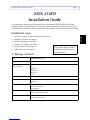
Installation steps
1. Check the package contents against the list below.
2. Hardware overview. See page 4.
3. Install the hardware. See page 7.
4. Assign an IP address. See page 8.
5. Set the password. See page 12.
6. Adjust the focus. See page 13.
1. Package contents
Item Models/variants/notes
Fixed Dome Network camera AXIS 216FD
PS-H indoor power supply
(country specific)
Europe
UK
Australia
USA/Japan
Argentina
Korea
Power supply extension cable 1.8 meters
Terminal block connector 4-pin connector block for connecting external devices to the I/O terminal
connector
Mounting kit Screwdriver for tamper-proof screws
Tamper-proof screws
Drill template
CD AXIS Network Video Product CD, including installation tools and other soft-
ware, product documentation
Printed Materials AXIS 216FD Installation Guide (this document)
Axis Warranty Document
Important!
This product must be used in
compliance with local laws
and regulations.

Page 4 AXIS 216FD Installation Guide
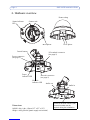
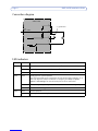
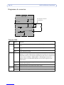
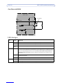
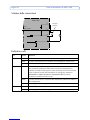
2. Hardware overview
Product ID & Serial number (S/N).
The serial number may be
required during the installation.
Dimensions
HxWxD = 94 x 144 x 132mm (3.7" x 5.7" x 5.2")
Weight = 425g (0.94 lb) (power supply not included)
Cover plates
Microphone
Network
indicator LED
Camera unit
Dome casing
Status indicator
LED
Control button
Power connector
(see page 5)
Network connector
(see page 5)
I/O terminal connector
(see page 5)
Power
indicator LED
Audio out
Audio in

AXIS 216FD Installation Guide Page 5
ENGLISH
ENGLISH
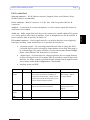
Unit connectors
Network connector - RJ-45 Ethernet connector. Supports Power over Ethernet. Using
shielded cables is recommended.
Power connector - Mini DC connector. 5.1V DC, max 3.6W. See product label for ±
connection.
Audio in - 3.5mm input for a mono microphone, or a line-in mono signal (left channel is
used from a stereo signal).
Audio out - Audio output (line level) that can be connected to a public address (PA) system
or an active speaker with a built-in amplifier. A pair of headphones can also be attached. A
stereo connector must be used for the audio out.
I/O terminal connector - Used in applications for e.g. motion detection, event triggering,
time lapse recording, alarm notifications, etc. It provides the interface to:
• 1 transistor output - For connecting external devices such as relays and LED:s.
Connected devices can be activated by Output buttons on the Live View page or
by an Event Type. The output will show as active (shown under Event Configu-
ration > Port Status) if the alarm device is activated.
• 1 digital input - An alarm input for connecting devices that can toggle between
an open and closed circuit, for example: PIRs, door/window contacts, glass break
detectors, etc. When a signal is received the state changes and the input becomes
active (shown under Event Configuration > Port Status).
• Auxiliary power and GND
Function Pin number Notes Specifications
Transistor
Output
4 Uses an open-collector NPN transistor with
the emitter connected to the GND pin. If
used with an external relay, a diode must be
connected in parallel with the load, for pro-
tection against voltage transients.
Max load = 50mA
Max voltage = 24V DC
(to the transistor)
Digital Input 3 Connect to GND to activate, or leave float-
ing (or unconnected) to deactivate.
Must not be exposed to
voltages greater than
10V DC
3.3V DC
Power
2 Can be used to power auxiliary equipment. Max load = 50mA
GND 1

Page 6 AXIS 216FD Installation Guide
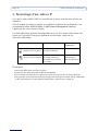
Connection diagram
LED indicators
LED Color Indication
Network Green Steady for connection to a 100 Mbit/s network. Flashes for network activity.
Amber Steady for connection to 10 Mbit/s network. Flashes for network activity.
Unlit No network connection.
Status Green Steady green for normal operation.
Note: The Status LED can be configured to be unlit during normal operation, or to
flash only when the camera is accessed. To configure, go to Setup > System
Options > LED settings. See the online help files for more information.
Amber Steady during startup, during reset to factory default or when restoring settings.
Red Slow flash for failed upgrade.
Power Green Normal operation.
Amber Flashes green/amber during firmware upgrade.
o
z
AXIS 216FD
3.3V
max. 50mA
e.g. pushbutton
4
o
3
o
o
2
1

AXIS 216FD Installation Guide Page 7
ENGLISH
ENGLISH
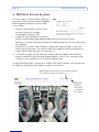
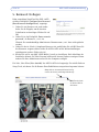
3. Install the hardware
3a. Mount the camera
The AXIS 216FD can be mounted with the cables routed through the wall/ceiling, or from
above or below. There are cover plates for the openings on both sides of the dome cover. See
the illustations on page 4.
To mount the AXIS 216FD on e.g. a drop (suspended) ceiling, it is important to check that
the ceiling material is strong enough to hold the weight of the camera.
Please see www.axis.com for available mounting accessories.
1. Using the drill template, drill two holes in the ceiling/wall.
2. Route and connect all the required cables. See 3b. Connect the cables, below.
3. Fasten the camera unit to a ceiling or wall, using screws and plugs appropriate for the
ceiling/wall material.
4. Ensure the camera is positioned so that the tamper-proof screws can be tightened using
the supplied screwdriver.
3b. Connect the cables
1. Connect the camera to the network using a shielded network cable.
2. Optionally connect external input/output devices, e.g. alarm devices. See page 5 for
information on the terminal connector pins.
3. Optionally connect an active speaker and/or external microphone.
4. Connect power, using one of the methods listed below:
• PoE (Power over Ethernet). If available, this is automatically detected when the
network cable is connected (see above).
• Connect the supplied indoor power supply to the power connector on the camera.
5. Check that the indicator LED:s indicate the correct conditions. See the table on page 6
for further details. Note that some LED:s can be disabled and may be unlit.
!IMPORTANT! - The casing of the AXIS 216FD is not approved for outdoor use
- the product may only be installed in indoor environments.

Page 8 AXIS 216FD Installation Guide
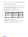
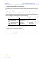
4. Assign an IP address
To make it accessible on the network, the AXIS 216FD must be assigned an IP address.
Depending on the number of cameras you wish to install, the recommended method for
setting IP addresses in Windows is either AXIS IP Utility or AXIS Camera Management. Use
the method that best suits your purpose.
Both of these applications are free of charge and are available on the Axis Network Video
Product CD supplied with this product, or they can be downloaded from www.axis.com/
techsup
Notes:
• A network DHCP server is optional.
• The AXIS 216FD has the default IP address 192.168.0.90
• If setting the IP address fails, check that there is no firewall blocking the operation.
• For other methods of setting or discovering the IP address of the AXIS 216FD, e.g. in other operating
systems, see page 11.
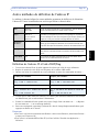
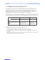
Method Recommended for Operating system
AXIS IP Utility
See page 9
Single cameras
Small installations
Windows
AXIS Camera Management
See page 10
Multiple cameras
Large installations
Installations on other subnets
Windows 2000
Windows XP Pro
Windows 2003 Server

AXIS 216FD Installation Guide Page 9
ENGLISH
ENGLISH
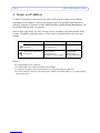
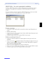
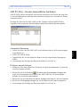
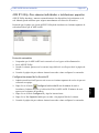
AXIS IP Utility - single camera/small installation
AXIS IP Utility automatically discovers and displays Axis devices on your network. The
application can also be used to manually set a static IP address.
Note that the computer running AXIS IP Utility must be on the same network segment
(physical subnet) as the AXIS 216FD.
Automatic discovery
1. Check that the AXIS 216FD is connected to the network and that power has been
applied.
2. Start AXIS IP Utility.
3. When the camera appears in the window, double-click it to open its home page.
4. See page 12 for instructions on how to set the password.
Set the IP address manually
1. Acquire an unused IP address on the same network segment as your computer.
2. Click the button Set IP address using serial number and enter the serial number
and IP address for the AXIS 216FD. The serial number is located on the product label.
3. Click the Set IP button and follow the instructions.
4. Click View Home Page button to access the camera’s web pages.
5. See page 12 for instructions on how to set the password.

Page 10 AXIS 216FD Installation Guide
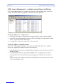
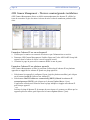
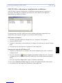
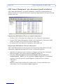
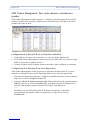
AXIS Camera Management - multiple cameras/large installations
AXIS Camera Management can automatically find and set IP addresses, show connection
status, and manage firmware upgrades for multiple Axis video products.
Set the IP address for a single device
1. Check that the camera is connected to the network and that power has been applied.
2. Start AXIS Camera Management. When the AXIS 216FD appears in the window, double-
click it to open the camera’s home page.
3. See page 12 for instructions on how to set the password.
Set the IP address in multiple devices
AXIS Camera Management speeds up the process of assigning IP addresses to multiple
devices, by suggesting IP addresses from a specified range.
1. Select the devices you wish to configure (different models can be selected) and click the
Assign IP button.
2. Select Obtain IP addresses automatically (DHCP), click the Update button and the
program will search in the specified range and suggest an IP address for each device.
-or-
Enter the range of IP addresses, the subnet mask and default router that devices can use
and click the Update button.

AXIS 216FD Installation Guide Page 11
ENGLISH
ENGLISH
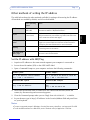
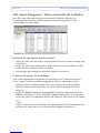
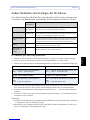
Other methods of setting the IP address
The table below shows the other methods available for setting or discovering the IP address.
All methods are enabled by default, and all can be disabled.
Set the IP address with ARP/Ping
1. Acquire an IP address on the same network segment your computer is connected to.
2. Locate the serial number (S/N) on the AXIS 216FD label.
3. Open a Command Prompt on your computer and enter the following commands:
4. Check that the network cable is connected to the camera and then start/restart the
camera, by disconnecting and reconnecting power.
5. Close the Command prompt when you see ‘Reply from 192.168.0.125: ...’ or similar.
6. In your browser, type in http://<IP address> in the Location/Address field and press Enter
on your keyboard.
Notes:
• To open a command prompt in Windows: from the Start menu, select Run... and type cmd. Click OK.
• To use the ARP command on a Mac OS X, use the Terminal utility in Application > Utilities.
Use in operating
system
Notes
UPnP™
Windows
(ME or XP)
When enabled on your computer, the camera is automatically
detected and added to “My Network Places.”
Bonjour MAC OSX
(10.4 or later)
Applicable to browsers with support for Bonjour. Navigate to the
Bonjour bookmark in your browser (e.g. Safari) and click on the
link to access the camera’s web pages.
AXIS Dynamic DNS
Service
All A free service from Axis that allows you to quickly and simply
install your camera. Requires an Internet connection with no
HTTP proxy. See www.axiscam.net for more information.
ARP/Ping All See below. The command must be issued within 2 minutes of
connecting power to the camera.
View DHCP server
admin pages
All To view the admin pages for the network DHCP server, please see
the server’s own documentation.
Windows syntax Windows example
arp -s <IP Address> <Serial Number>
ping -l 408 -t <IP Address> arp -s 192.168.0.125 00-40-8c-18-10-00
ping -l 408 -t 192.168.0.125
UNIX/Linux/Mac syntax UNIX/Linux/Mac example
arp -s <IP Address> <Serial Number> temp
ping -s 408 <IP Address> arp -s 192.168.0.125 00:40:8c:18:10:00
temp
ping -s 408 192.168.0.125

Page 12 AXIS 216FD Installation Guide
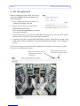
5. Set the password
When accessing the AXIS 216FD for the first
time, the ‘Configure Root Password’ dialog
will be displayed.
1. Enter a password and then re-enter it, to
confirm the spelling. Click OK.
2. Enter the user name root in the ‘Enter
Network Password’ dialog.
Note: The default administrator user name
root cannot be deleted.
3. Enter the password as set above, and click OK. If the password is lost, the AXIS 216FD
must be reset to the factory default settings. See page 14.
4. If required, click Yes to install AMC (AXIS Media Control), which allows viewing of the
video stream in Internet Explorer. You will need administrator rights on the computer to
do this.
The Live View page of the AXIS 216FD is displayed, with links to the Setup tools, which
allow you to customize the camera.
Setup - Provides all the tools for
configuring the camera to
requirements.
Help - Displays online help on
all aspects of using the camera.

AXIS 216FD Installation Guide Page 13
ENGLISH
ENGLISH
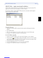
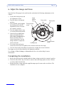
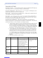
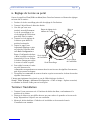
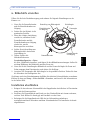
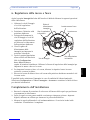
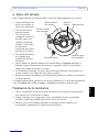
6. Adjust the image and focus
Open the Live View page in the web interface and make the following adjustments to the
camera:
1. Loosen the locking screw and
tilt adjustment screws.
2. Turn the lens to the desired
position.
3. Once satisfied, gently tighten
the locking screw and tilt
adjustment screws to secure
the camera’s position.
4. Turn the image balance ring
to set the horizontal position.
5. Open the Focus Adjustment
page in the Web interface
under Basic Configuration >
Focus and follow the on-
screen instructions. Use the
image window to adjust the
focus and zoom.
6. To set the focus and zoom,
loosen the zoom and focus pullers anti-clockwise and rotate the rings.
7. Lock the focus and zoom pullers in position by rotating the screws clockwise.
The image can also be fine-tuned for low lighting conditions.
Go to Setup > Video & Image > Advanced and refer to the online help for more
information.
Completing the installation
1. Rotate the black protective shield inside the dome casing to match the camera’s position.
2. Clean the dome with a dry soft cloth to remove dust and finger prints and use a blower
to remove dust from the lens.
3. Mount the dome casing using the supplied tamper-proof screws and screw driver. The
installation is now complete.
Image
Focus puller Zoom puller
screw
Tilt adjustment
screw
Tilt adjustment
balance
ring
Locking screw

Page 14 AXIS 216FD Installation Guide
Resetting to the Factory Default Settings
This will reset all parameters, including the IP address, to the Factory Default settings:
1. Disconnect power from the camera.
2. Press and hold the Control button and reconnect power.
3. Keep the Control button pressed until the Power indicator flashes amber (this may take
up to 15 seconds).
4. Release the Control button. When the Power indicator displays green (which can take up
to 1 minute) the process is complete and the camera has been reset.
5. Re-install the AXIS 216FD using one of the methods described in this document.
It is also possible to reset parameters to the original factory default settings via the web
interface. For more information, please see the online help or the user’s manual.
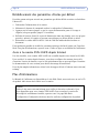
Accessing the AXIS 216FD from the Internet
Once installed, your AXIS 216FD is accessible on your local network (LAN). To access the
camera from the Internet, network routers must be configured to allow incoming traffic,
which is usually done on a specific port. Please refer to the documentation for your router
for further instructions.
For more information on this and other topics, please visit the Axis Support Web at
www.axis.com/techsup
Further information
The user’s manual is available from the Axis Web site at www.axis.com or from the Axis
Network Video Product CD supplied with this product.
Tip!
Visit www.axis.com/techsup to check if there is updated firmware available for your
AXIS 216FD. To see the currently installed firmware version, see the Basic
Configuration web page in the product’s setup tools.

AXIS 216FD Guide d’installation Page 15
FRANCAIS
AXIS 216FD
Guide d'installation
Ce guide d'installation vous explique comment installer la AXIS 216FD sur votre réseau.
Pour d'autres informations sur l'utilisation de ce produit, consultez le Manuel de l'utilisateur,
disponible sur le CD fourni, ou visitez le site www.axis.com/techsup.
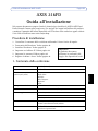
Étapes de l'installation
1. Vérifiez le contenu de la livraison à l'aide de la liste ci-dessous.
2. Présentation du matériel. Reportez-vous à la page 16.
3. Installez le matériel. Reportez-vous à la page 19.
4. Paramétrez une adresse IP. Reportez-vous à la
page 20.
5. Définissez le mot de passe. Reportez-vous à la
page 24.
6. Réglez la mise au point. Reportez-vous à la page 25.
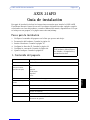
1. Contenu de l'emballage
Article Modèles/variantes/remarques
Caméra réseau AXIS 216FD
Alimentation intérieure PS-H
(dépend du pays)
Europe
Royaume-Uni
Australie
États-Unis/Japon
Argentine
Corée
Prolongateur de câble d’ali-
mentation
1,8 mètres
Connecteur pour terminaux Connecteur 4 broches pour la connexion d'équipements externes au connec-
teur E/S
Kit de montage Tournevis pour vis inviolables
Vis inviolables
Gabarit de perçage
CD CD de la caméra vidéo réseau Axis comprenant les outils d'installation, les
autres logiciels et la documentation
Documentation AXIS 216FD Guide d'installation (le présent document)
Document de garantie d'Axis
Important !
Ce produit doit être utilisé
conformément aux lois et
dispositions locales en
vigueur.

Page 16 AXIS 216FD Guide d’installation
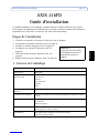
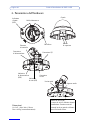
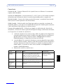
2. Présentation du matériel
Microphone
Dimensions
H x L x P = 94 x 144 x 132mm
Poids = 425g (alimentation exclue)
Connecteur de réseau
(reportez-vous à la page 17)
Connecteur pour terminaux E/S
(reportez-vous à la page 17)
Connecteur d'alimentation
(reportez-vous à la
page 17)
Témoin DEL d’état
ID du produit et numéro de série
(S/N). Le numéro de série peut
être requis pendant l'installation.
Témoin
DEL réseau
Bouton de
commande
Témoin DEL
d’alimentation
Capot plaques
Boîtier du dôme
Caméra
Sortie audio Entrée audio

AXIS 216FD Guide d’installation Page 17
FRANCAIS
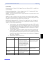
Connecteurs de l'unité
Connecteur de réseau - Connecteur Ethernet RJ-45. Supporte l'Alimentation Eléctrique par
Câble Ethernet (PoE). Il est recommandé d'utiliser des câbles blindés.
Connecteur d’alimentation - Miniconnecteur CC. 5,1 V CC, jusqu'à 3.6W. Reportez-vous à
l'étiquette du produit pour connaître la connexion ±
Entrée audio - 3.5 mm entrée pour microphone mono , ou ligne entrée en signale mono (le
canal à gauche est utilisé pour le signal stéréo).
Sortie audio - sortie audio qui peut être connecté à un système d'adresse publique(PA) ou
haut parleur actif avec amplificateur intégré. Une paire d'écouteur peut être auss connecté.
Un connecteur stéréo doit être utilisé pour la sortie audio.
Connecteur pour terminaux E/S - Utilisé dans les applications, par exemple pour la
détection de mouvement, le déclenchement d'événements, l'enregistrement à intervalles, les
notifications d'alarme, etc. Il sert d'interface aux éléments suivants:
• 1 sortie transistor: permet de connecter des dispositifs externes, comme des relais
ou DELs. Les dispositifs connectés peuvent être activés à l'aide des boutons de
sortie sur la page Live View (Vidéo en direct) ou à l'aide d'un type d'événement.
La sortie est considérée comme étant active (Event Configuration (Configuration
d'événement) > Port Status (État du port)) si le dispositif d'alarme est activé.
• 1 entrée numérique: entrée d'alarme utilisée pour connecter des dispositifs pou-
vant passer d'un circuit ouvert à un circuit fermé, par exemple : les détecteurs
infrarouge passifs, les contacts de porte/fenêtre, les détecteurs de bris de verre,
etc. Lorsqu'un signal est reçu, l'état change et l'entrée devient active (elle appa-
raît sous Event Configuration (Configuration d'événement) > Port Status (État
du port)).
• Alimentation auxiliaire et mise à la terre.
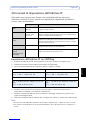
Fonction Numéro de broche Remarques Spécifications
Sortie tran-
sistor
4 Utilise un transistor NPN à collec-
teur ouvert avec émetteur con-
necté au contact à la masse. En
cas d'utilisation avec un relais
externe, une diode doit être con-
nectée en parallèle avec la
charge, comme protection contre
les tensions transitoires.
Charge maximale = 50mA
Tension maximale = 24VCC
(en entrée)
Entrée
numérique
3 Connectez-la au GND pour
l'activer ou laissez-la flotter (ou
déconnectée) pour la désactiver.
Ne doit pas être exposée à
une tension supérieure à
10 V CC
Alimentation
auxiliaire
3.3V CC
2 Cette broche peut également
servir à alimenter le matériel aux-
iliaire.
Intensité maximale: 50 mA.
GND 1 Terre.

Page 18 AXIS 216FD Guide d’installation
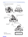
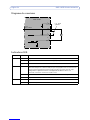
Diagramme de connexion
Témoins DEL
DEL Couleur Indication
Réseau Vert Continu en cas de connexion à un réseau 100 Mbits/s. Clignote en cas d'activité
réseau.
Orange Continu en cas de connexion à un réseau 10 Mbits/s. Clignote en cas d'activité
réseau.
Éteint Pas de connexion à réseau.
État Vert Vert continu en cas de fonctionnement normal.
Remarque : Le voyant d'état peut être configuré pour être éteint au cours du fonc-
tionnement normal, ou pour clignoter uniquement lors des accès à la caméra. Pour
ce faire, cliquez sur Setup > System Options > LED settings (Configuration >
Options système > Paramètres DEL). Reportez-vous à l'aide en ligne pour plus
d'informations.
Orange En continu pendant le démarrage, la réinitialisation des valeurs d'usine ou la res-
tauration des paramètres.
Rouge Clignote lentement en cas d'échec de la mise à niveau.
Alimen-
tation
Vert Fonctionnement normal.
Orange Clignote en vert/orange pendant la mise à niveau du microprogramme.
o
z
AXIS 216FD
3.3V
max. 50mA
4
o
3
o
o
2
1Par exemple, un bouton
de commande

AXIS 216FD Guide d’installation Page 19
FRANCAIS
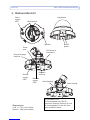
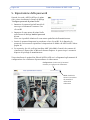
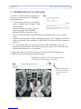
3. Installation du matériel
3a. Montage de la caméra
La caméra AXIS 216FD peut être montée avec les câbles d'alimentation et réseau acheminés
dans le mur/plafond, ou depuis le haut ou le bas. Vous disposez de plaques d'obturation pour
les ouvertures des deux côtés du capot du dôme. Consultez les figures de la page 16.
Pour monter l'AXIS 216FD sur un faux-plafond , il est important de vérifier que le matériel
du plafond est assez solide pour supporter le poigd de la caméra.
Voir www.axis.com pour les accessoires de montage disponibles.
1. Avec le gabarit de perçage, percez deux trous dans le plafond/mur.
2. Orienter et connecter tous les câbles néccessaires. Voi 3b. Branchement des câbles, en
bas.
3. Fixez la caméra au plafond ou au mur à l'aide des vis et des chevilles appropriées.
4. Veillez à ce que la caméra soit positionnée de telle manière que les vis inviolables
puissent être serrées à l'aide du tournevis fourni.
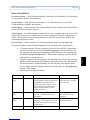
3b. Branchement des câbles
1. Connectez la caméra à votre réseau à l'aide d'un câble de réseau blindé.
2. Si vous le souhaitez, connectez des dispositifs externes, par exemple des dispositifs
d'alarme. Reportez-vous à la page 17 pour plus d'informations sur les broches du
connecteur pour terminaux.
3. Si vous le souhaitez, connectez un haut-parleur actif pour la transmission audio
bidirectionnelle.
4. Branchez l'alimentation à l'aide de l'une des méthodes reprises ci-dessous.
• PoE (Alimentation éléctrique par câble ethernet). Si disponible, ceci est automa-
tiquement détecté quand le câble résau est connecté (Voir au -dessus).
• Branchez l'alimentation intérieure fournie au connecteur d'alimentation de la
caméra.
5. Vérifiez que les témoins DEL indiquent les conditions correctes. Pour plus
d'informations, consultez le tableau à la page 18. Notez que certains témoins DEL
peuvent être désactivés et éteints.
!IMPORTANT! - Le boitier de l'AXIS 216FD n'est pas approuvé pour une
utilisation extérieure - Le produit doit être uniquement installé en intérieur.

Page 20 AXIS 216FD Guide d’installation
4. Paramétrage d'une adresse IP
Pour que la caméra AXIS 216FD soit accessible sur le réseau, vous devez lui affecter une
adresse IP.
Selon le nombre de caméras à installer, pour définir des adresses IP sous Windows, il est
recommandé d'utiliser AXIS IP Utility ou AXIS Camera Management. Employez
l'application qui vous convient le mieux.
Ces deux applications gratuites sont disponibles sur le CD de la caméra vidéo réseau Axis
fourni avec ce produit. Vous pouvez également les télécharger à partir du site
www.axis.com/techsup.
Remarques
• Un serveur DHCP réseau est fourni en option.
• L'adresse IP par défaut de la AXIS 216FD est 192.168.0.90.
• En cas d'échec de la définition de l'adresse IP, vérifiez qu'aucun pare-feu ne bloque l'opération.
• Pour connaître les autres méthodes de paramétrage ou de repérage de l'adresse IP de la caméra AXIS
216FD, par exemple sur d'autres systèmes d'exploitation, reportez-vous à la page 23.
Méthode Recommandée pour Système
d'exploitation
AXIS IP Utility
Reportez-vous à la page 21
Une seule caméra
Les petites installations
Windows
AXIS Camera Management
Reportez-vous à la page 22
Plusieurs caméras
Les grandes installations
Les installations sur d'autres
sous-réseaux
Windows 2000
Windows XP Pro
Windows 2003 Server
La pagina si sta caricando...
La pagina si sta caricando...
La pagina si sta caricando...
La pagina si sta caricando...
La pagina si sta caricando...
La pagina si sta caricando...
La pagina si sta caricando...
La pagina si sta caricando...
La pagina si sta caricando...
La pagina si sta caricando...
La pagina si sta caricando...
La pagina si sta caricando...
La pagina si sta caricando...
La pagina si sta caricando...
La pagina si sta caricando...
La pagina si sta caricando...
La pagina si sta caricando...
La pagina si sta caricando...
La pagina si sta caricando...
La pagina si sta caricando...
La pagina si sta caricando...
La pagina si sta caricando...
La pagina si sta caricando...
La pagina si sta caricando...
La pagina si sta caricando...
La pagina si sta caricando...
La pagina si sta caricando...
La pagina si sta caricando...
La pagina si sta caricando...
La pagina si sta caricando...
La pagina si sta caricando...
La pagina si sta caricando...
La pagina si sta caricando...
La pagina si sta caricando...
La pagina si sta caricando...
La pagina si sta caricando...
La pagina si sta caricando...
La pagina si sta caricando...
La pagina si sta caricando...
La pagina si sta caricando...
La pagina si sta caricando...
La pagina si sta caricando...
La pagina si sta caricando...
-
 1
1
-
 2
2
-
 3
3
-
 4
4
-
 5
5
-
 6
6
-
 7
7
-
 8
8
-
 9
9
-
 10
10
-
 11
11
-
 12
12
-
 13
13
-
 14
14
-
 15
15
-
 16
16
-
 17
17
-
 18
18
-
 19
19
-
 20
20
-
 21
21
-
 22
22
-
 23
23
-
 24
24
-
 25
25
-
 26
26
-
 27
27
-
 28
28
-
 29
29
-
 30
30
-
 31
31
-
 32
32
-
 33
33
-
 34
34
-
 35
35
-
 36
36
-
 37
37
-
 38
38
-
 39
39
-
 40
40
-
 41
41
-
 42
42
-
 43
43
-
 44
44
-
 45
45
-
 46
46
-
 47
47
-
 48
48
-
 49
49
-
 50
50
-
 51
51
-
 52
52
-
 53
53
-
 54
54
-
 55
55
-
 56
56
-
 57
57
-
 58
58
-
 59
59
-
 60
60
-
 61
61
-
 62
62
-
 63
63


Axis AXIS 216FD Guida d'installazione
- Categoria
- Telecamere di sicurezza
- Tipo
- Guida d'installazione
in altre lingue
- English: Axis AXIS 216FD Installation guide
- français: Axis AXIS 216FD Guide d'installation
- español: Axis AXIS 216FD Guía de instalación
- Deutsch: Axis AXIS 216FD Installationsanleitung
- português: Axis AXIS 216FD Guia de instalação