Pioneer AVIC Z620 BT Manuale utente
- Categoria
- Subwoofer
- Tipo
- Manuale utente
Questo manuale è adatto anche per

English Français Italiano Español Deutsch Nederlands
AVIC-Z920DAB
AVIC-Z820DAB
AVIC-Z720DAB
AVIC-Z620BT
AVIC-Z7210DAB
AVIC-Z6210BT
NAVIGATION AV SYSTEM
SYSTÈME DE NAVIGATION AV
SISTEMA DI NAVIGAZIONE AV
SISTEMA DE NAVEGACIÓN AV
NAVIGATIONS-/AV-SYSTEM
AV NAVIGATIESYSTEEM
Installation Manual
Manuel d'installation
Manuale d'installazione
Manual de instalación
Installationsanleitung
Installatiehandleiding

2En
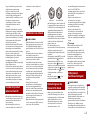
• The navigation features of this product
(and the rear view camera option if
purchased) are intended solely to aid you
in the operation of your vehicle. It is not a
substitute for your attentiveness,
judgement and care when driving.
• Never use this product to route to
hospitals, police stations, or similar
facilities in an emergency. Please call the
appropriate emergency number.
• Do not operate this product, any
applications, or the rear view camera
option (if purchased) if doing so will
divert your attention in any way from the
safe operation of your vehicle. Always
observe safe driving rules and follow all
existing traffic regulations. If you
experience difficulty in operating this
product, pull over, park your vehicle in a
safe location and apply the handbrake
before making the necessary
adjustments.
• This manual explains how to install this
product in your vehicle. Operation of this
product is explained in the separate
manuals.
• Do not install this product where it may
(i) obstruct the driver’s vision,
(ii) impair the performance of any of the
vehicle’s operating systems of safety
features, including airbags, hazard lamp
buttons, or
(iii) impair the driver’s ability to safely
operate the vehicle.
In some cases, it may not be possible to
install this product because of the vehicle
type or the shape of the vehicle interior.
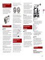
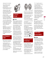
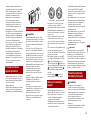
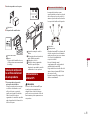
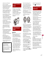
• Model icons shown in this manual
indicate that the description is intended
for the models indicated by the icons. If
the following icon is shown, the
description is applied only to the model
shown.
e.g.)
WARNING
Pioneer does not recommend that you
install this product yourself. This product is
designed for professional installation only.
We recommend that only authorised
Pioneer service personnel, who have
special training and experience in mobile
electronics, set up and install this product.
NEVER SERVICE THIS PRODUCT YOURSELF.
Installing or servicing this product and its
connecting cables may expose you to the
risk of electric shock or other hazards, and
can cause damage to this product that is
not covered by warranty.
• Read this manual fully and carefully
before installing this product.
• Keep this manual handy for future
reference.
• Pay close attention to all warnings in this
manual and follow the instructions
carefully.
• This product may in certain
circumstances display inaccurate position
of your vehicle, the distance of objects
shown on the screen, and compass
directions. In addition, the system has
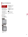
Connection
Precautions
Your new product and this
manual
Important safeguards
Z000DAB
certain limitations, including the inability
to identify one-way streets, temporary
traffic restrictions and potentially unsafe
driving areas. Please exercise your own
judgement in the light of actual driving
conditions.
• As with any accessory in your vehicle’s
interior, this product should not divert
your attention from the safe operation of
your vehicle as it may result in serious
injury or death. If you experience
difficulty in operating the system or
reading the display, please make
adjustments while safely parked.
• Please remember to wear your seat belt
at all times while operating your vehicle.
If you are in an accident, your injuries can
be considerably more severe if your seat
belt is not properly fastened.
• Certain country and government laws
may prohibit or restrict the placement
and use of this product in your vehicle.
Please comply with all applicable laws
and regulations regarding the use,
installation and operation of this product.
WARNING
Do not take any steps to tamper with or
disable the handbrake interlock system
which is in place for your protection.
Tampering with or disabling the
handbrake interlock system could result in
serious injury or death.
CAUTION
• If you decide to perform the installation
yourself, and have special training and
experience in the mobile electronics
installations, please carefully follow all of
the steps in the installation manual.
• Secure all wiring with cable clamps or
electrical tape. Do not allow any bare
wiring to remain exposed.
• Do not directly connect the yellow lead of
this product to the vehicle battery. If the
lead is directly connected to the battery,
engine vibration may eventually cause
the insulation to fail at the point where
the wire passes from the passenger
compartment into the engine
compartment. If the yellow lead’s
insulation tears as a result of contact with
metal parts, short-circuiting can occur,
resulting in considerable danger.
• It is extremely dangerous to allow cables
to become wound around the steering
column or gearstick. Be sure to install this
product, its cables, and wiring away in
such so that they will not obstruct or
hinder driving.
• Make sure that the cables and wires will
not interfere with or become caught in
any of the vehicle’s moving parts,
especially the steering wheel, gearstick,
handbrake, sliding seat tracks, doors, or
any of the vehicle’s controls.
• Do not route wires where they will be
exposed to high temperatures. If the
insulation heats up, wires may become
damaged, resulting in a short circuit or
malfunction and permanent damage to
the product.
• Do not cut the GPS aerial cable to shorten
it or use an extension to make it longer.
Altering the aerial cable could result in a
short circuit or malfunction.
• Do not shorten any leads. If you do, the
protection circuit (fuse holder, fuse
resistor or filter, etc.) may fail to work
properly.
• Never feed power to other electronic
products by cutting the insulation of the
power supply lead of this product and
tapping into the lead. The current
capacity of the lead will be exceeded,
causing overheating.
Precautions before
connecting the system

3En
English
• Use this unit with a 12-volt battery and
negative earthing only. Failure to do so
may result in a fire or malfunction.
• To avoid shorts in the electrical system,
be sure to disconnect the (–) battery
cable before installation.
WARNING
• Use speakers over 50 W (maximum input
power) and between 4 Ω to 8 Ω
(impedance value). Do not use 1 Ω to 3 Ω
speakers for this product.
• The black lead is earth. Please earth this
lead separately from the earth of high
current products such as power amps. Do
not earth more than one product
together with the earth from another
product. For example, you must
separately earth any amp unit away from
the earth of this product. Connecting
earths together can cause a fire and/or
damage the products if their earths
became detached.
• When replacing the fuse, be sure to only
use a fuse of the rating prescribed on this
product.
• When disconnecting a connector, pull the
connector itself. Do not pull the lead, as
you may pull it out of the connector.
• This product cannot be installed in a
vehicle without ACC (accessory) position
on the ignition switch.
• To avoid short-circuiting, cover the
disconnected lead with insulating tape. It
is especially important to insulate all
unused speaker leads, which if left
uncovered may cause a short circuit.
• Attach the connectors of the same colour
to the corresponding coloured port, i.e.,
blue connector to the blue port, black to
black, etc.
• For connecting a power amp or other
devices to this product, refer to the
manual for the product to be connected.
• Since a unique BPTL circuit is employed,
do not directly earth the side of the
speaker lead or connect the side of
another side of the speaker lead together.
Be sure to connect the side of the
speaker lead to the side of the speaker
lead on this product.
• The graphical symbol placed on
the product means direct current.
• When the ignition switch is turned on
(ACC ON), a control signal is output
through the blue/white lead. Connect to
an external power amp’s system remote
control terminal, the auto-aerial relay
control terminal, or the aerial booster
power control terminal (max. 300 mA 12
V DC). The control signal is output
Before installing this
product
To prevent damage
Notice for the blue/
white lead
ACC position
No ACC position
through the blue/white lead, even if the
audio source is switched off.
• Be sure not to use this lead as the power
supply lead for the external power amps.
Such connection could cause excessive
current drain and malfunction.
• Be sure not to use this lead as the power
supply lead for the auto-aerial or aerial
booster. Such connection could cause
excessive current drain and malfunction.
Important
When this product is in [Power OFF] mode,
the control signal is also turned off. If
[Power OFF] mode is cancelled, the control
signal is output again and the aerial is
extended with the auto aerial function (if
the aerial is being used). Be careful so that
the extended aerial does not come into
contact with any obstacles.
WARNING
• To avoid the risk of accident and the
potential violation of applicable laws, this
product should never be used while the
vehicle is being driven except for
navigation purposes. And, also rear
displays should not be in a location
where it is a visible distraction to the
driver.
• In some countries, the viewing of images
on a display inside a vehicle even by
persons other than the driver may be
illegal. Where such regulations apply they
must be obeyed and this product’s video
source should not be used.
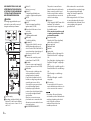
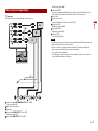
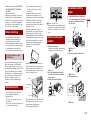
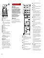
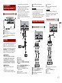
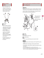
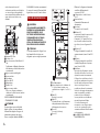
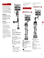
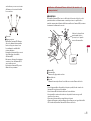
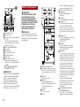
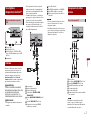
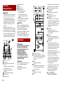
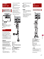
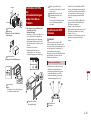
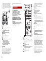
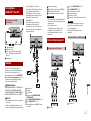
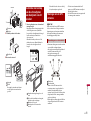
GPS aerial 3.55 m
Microphone 3 m
Vehicle Bus conversion cable 13 cm*.
Refer to the instruction manual for the
Vehicle Bus adapter (sold separately).
Digital Radio aerial input*
This product
Aerial jack
AV cable IN/OUT
Power supply
Fuse (10 A)
Wired remote input
Hard-wired remote control adapter can
be connected (sold separately).
*AVIC-Z920DAB/AVIC-Z820DAB/AVIC-
Z720DAB/AVIC-Z7210DAB
CAUTION
For improved Digital Radio reception,
make sure a Digital Radio aerial with
phantom power input (active type) is used.
Pioneer recommends using AN-DAB1 or
CA-AN-DAB.001 (sold separately). Current
consumption of the Digital Radio aerial
should be 100 mA or less.
WARNING
IMPROPER CONNECTION MAY RESULT IN
SERIOUS DAMAGE OR INJURY
Rear panel (main
terminals)
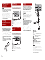
Power cord

4En
INCLUDING ELECTRICAL SHOCK, AND
INTERFERENCE WITH THE OPERATION
OF THE VEHICLE'S ANTILOCK BRAKING
SYSTEM, AUTOMATIC TRANSMISSION
AND SPEEDOMETER INDICATION.
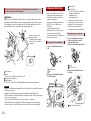
CAUTION
It is strongly suggested that the speed
pulse wire be connected for accuracy of
navigation and better performance.
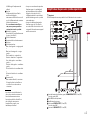
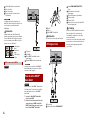
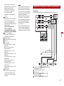
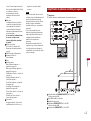
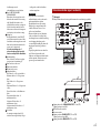
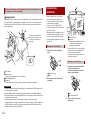
To power supply
Depending on the kind of vehicle, the
function of 2* and 4* may be different.
In this case, be sure to connect 1* to 4*
and 3* to 2*.
Yellow (2*)
Back-up (or accessory)
Yellow (1*)
To terminal supplied with power
regardless of ignition switch position.
Red (4*)
Accessory (or back-up)
Red (3*)
Connect to terminal controlled by
ignition switch (12 V DC).
Connect leads of the same colour to
each other.
Orange/white
To lighting switch terminal.
Black (earth)
To vehicle (metal) body.
Blue/white (5*)
The pin position of the ISO connector
will differ depending on the type of
vehicle. Connect 5* and 6* when Pin 5 is
an aerial control type. In another type of
vehicle, never connect 5* and 6*.
Blue/white (6*)
Connect to auto-aerial relay control
terminal (max. 300 mA 12 V DC).
Blue/white
Connect to system control terminal of
the power amp (max. 300 mA 12 V DC).
Violet/white
This is connected so that this product
can detect whether the vehicle is
moving forwards or backwards.
Connect the violet/white lead to the
lead whose voltage changes when the
gearstick is put in reverse. Unless
connected, the sensor may not detect
your vehicle travelling forwards/
backwards properly, and thus the
position of your vehicle detected by the
sensor may be misaligned from the
actual position.
When you use a rear view camera,
please make sure to connect this lead.
Otherwise you cannot switch to the rear
view camera picture.
Pink (CAR SPEED SIGNAL INPUT)
This product is connected here to
detect the distance the vehicle travels.
Always connect the vehicle’s speed
detection circuit. Failure to make this
connection will increase errors in the
vehicle’s location display.
Light green
Used to detect the ON/OFF status of the
handbrake. This lead must be
connected to the power supply side of
the handbrake switch.
If this connection is made incorrectly
or omitted, certain functions of this
product will be unusable.
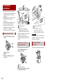
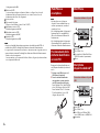
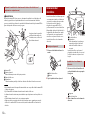
Connection method
Clamp the lead (1) then clamp firmly
with needle-nosed pliers (2).
Power supply side
Handbrake switch
Earth side
Speaker leads
White: Front left + or high range left +
White/black: Front left – or high range
left –
Grey: Front right + or high range right +
Grey/black: Front right – or high range
right –
Green: Rear left + or middle range left +
Green/black: Rear left – or middle range
left –
Violet: Rear right + or middle range
right +
Violet/black: Rear right – or middle
range right –
ISO connector
In some vehicles, the ISO connector
may be divided into two. In this case, be
sure to connect to both connectors.
NOTES
• The position of the speed detection
circuit and the position of the handbrake
switch vary depending on the vehicle
model. For details, consult your
authorised Pioneer dealer or an
installation professional.
• When a subwoofer is connected to this
product instead of a rear speaker, change
the rear output setting in the initial
setting. The subwoofer output of this
product is monaural.
• When using a subwoofer of 2 Ω, be sure
to connect the subwoofer to the violet
and violet/black leads of this unit. Do not
connect anything to the green and
green/black leads.

5En
English
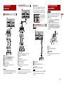
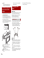
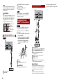
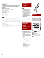
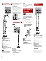
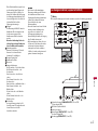
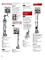
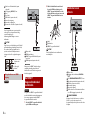
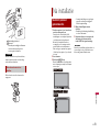
Important
The speaker leads are not used when this connection is in use.
Subwoofer output (SUBWOOFER OUTPUT) 23 cm (STD)
Low range output (NW)
RCA cable (sold separately)
Power amp
Front output (FRONT OUTPUT) 15 cm (STD)
High range output (NW)
Rear output (REAR OUTPUT) 15 cm (STD)
Power amp (sold separately)
Middle range output (NW)
Yellow/black (MUTE)
If you use an equipment with Mute function, wire this lead to the Audio Mute lead on
that equipment. If not, keep the Audio Mute lead free of any connections.
This product
System remote control
Connect to Blue/white cable (max. 300 mA 12 V DC).
Rear speaker (STD)
Middle range speaker (NW)
Front speaker (STD)
High range speaker (NW)
Subwoofer (STD)
Low range speaker (NW)
NOTES
• Select the appropriate speaker mode between standard mode (STD) and network mode
(NW). For details, refer to the Operation Manual.
• Audio source will be set to mute or attenuate, while the following sounds will not be
muted or attenuated. For details, refer to Operation Manual.
–Voice guidance of the navigation
–Incoming ring tone and incoming voice of the mobile phone that is connected to this
product via Bluetooth wireless technology

6En
NOTES
• For details on how to connect an external
device using a separately sold cable, refer
to the manual for the cable.
• For details concerning the connection,
operations and compatibility of the
iPhone, refer to the Operation Manual.
• For details concerning the connection
and operations of the smartphone, refer
to the Operation Manual.
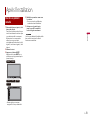
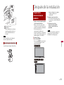
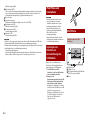
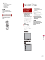
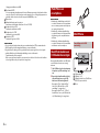
Attach identification labels to USB cables
before installing this product in a vehicle.
1 Connect USB cables to the USB port 1
and 2 on the rear of this product.
2 Attach the identification labels
corresponding to each port to the USB
cables as illustrated below.
Attach the “Port 1 Apple CarPlay” label
to the USB cable connected to the USB
port 1.
Attach the “Port 2” or “Port 2 Android
Auto” label to the USB cable connected
to the USB port 2.
USB port1
USB cable 1.5 m
USB interface cable for iPod/iPhone (CD-
IU52) (sold separately)
iPhone
USB port2
USB cable 1.5 m
USB - micro USB cable (Type USB A -
micro USB B) (supplied with CD-MU200)
Smartphone
iPod/iPhone and
smartphone
Attaching
identification labels to
USB cables
iPod/iPhone
Connecting via the USB port
Smartphone (Android™
device)
Connecting via the USB port
When you use the rear view camera, the
rear view image is automatically switched
from the video by moving the gearstick to
REVERSE (R). Camera View mode also
allows you to check what is behind you
while driving.
WARNING
USE INPUT ONLY FOR REVERSE OR MIRROR
IMAGE REAR VIEW CAMERA. OTHER USE
MAY RESULT IN INJURY OR DAMAGE.
CAUTION
• The screen image may appear reversed.
• With the rear view camera you can keep
an eye on trailers, or back into a tight
parking spot. Do not use for
entertainment purposes.
• Objects in rear view may appear closer or
more distant than in reality.
• The image area of full-screen images
displayed while backing or checking the
rear of the vehicle may differ slightly.
This product
Power supply
Power cord
Violet/white (REVERSE-GEAR SIGNAL
INPUT)
Brown (REAR VIEW CAMERA IN) 23 cm
Yellow (VIDEO INPUT) 23 cm
Rear view camera (ND-BC8) (sold
separately)
To video output
RCA cable (supplied with ND-BC8)
RCA cable (sold separately)
View camera (sold separately)
NOTES
• Connect only the rear view camera to
brown cable. Do not connect any other
equipment.
• Some appropriate settings are required
to use rear view cameras. For details, refer
to the Operation Manual.
Camera

7En
English
This product
Red, white (AUDIO INPUT) 23 cm
Yellow (VIDEO INPUT) 23 cm
RCA cable (sold separately)
To audio input
To video input
External video component (sold
separately)
NOTE
The appropriate setting is required to use
the external video component. For details,
refer to the Operation Manual.
This product
Mini-jack AV cable (sold separately)
AUX input (AUX IN) 15 cm
Yellow
Red, white
RCA cables (sold separately)
To video output
To audio outputs
External video component (sold
separately)
NOTE
The appropriate setting is required to use
the external video component. For details,
refer to the Operation Manual.
External video
component
Using AV input
Using an AUX input
CAUTION
Be sure to use a mini-jack AV cable (sold
separately) for wiring. If you use other
cables, the wiring position might differ
resulting in disturbed images and sounds.
This product
HDMI port
High Speed HDMI™ Cable (sold
separately)
HDMI device (sold separately)
NOTE
When you connect the High Speed HDMI™
Cable, use the lock tie to fix it securely
(page 7).
Be sure to fix the High Speed HDMI™ Cable
with the lock tie, when you connect the
external device with the High Speed
HDMI™ Cable.
1 Insert the High Speed HDMI™ Cable
into the HDMI port.
2 Wrap the lock tie around the hook
above the HDMI port and the High
Speed HDMI™ Cable, and then tighten
it to secure the High Speed HDMI™
Cable.
Hook
Lock tie
High Speed HDMI™ Cable
CAUTION
Do not tighten up the lock tie more than
necessary.
Using an HDMI input
L : Left audio (White)
R : Right audio (Red)
V : Video (Yellow)
G : Earth
Z920DAB
Securing the High
Speed HDMI™
Z920DAB

8En
This product
Rear audio output (R. AUDIO OUT)
Yellow (REAR MONITOR OUTPUT) 30
cm
Mini pin plug cable (sold separately)
RCA cables (sold separately)
To audio input
To video input
Rear display with RCA input jacks (sold
separately)
WARNING
NEVER install the rear display in a location
that enables the driver to watch the video
source while driving.
This product’s rear video output is for
connection of a display to enable
passengers in the rear seats to watch the
video source.
Rear display
CAUTION
• Never install this product in places where,
or in a manner that:
–Could injure the driver or passengers if
the vehicle stops suddenly.
– May interfere with the driver’s operation
of the vehicle, such as on the floor in
front of the driver’s seat, or close to the
steering wheel or gearstick.
• Make sure there is nothing behind the
dashboard or panelling when drilling
holes in them. Be careful not to damage
fuel lines, brake lines, electronic
components, communication wires or
power cables.
• When using screws, do not allow them to
come into contact with any electrical
lead. Vibration may damage wires or
insulation, leading to a short circuit or
other damage to the vehicle.
• To ensure proper installation, be sure to
use the supplied parts in the manner
specified. If any parts are not supplied
with this product, use compatible parts in
the manner specified after you have the
part compatibility checked by your
dealer. If parts other than supplied or
compatible ones are used, they may
damage internal parts of this product or
they may work loose and the product
may become detached.
• It is extremely dangerous to allow cables
to become wound around the steering
column or gearstick. Be sure to install this
product, its cables, and wiring away in
such so that they will not obstruct or
hinder driving.
• Make sure that leads cannot get caught
in a door or the sliding mechanism of a
seat, resulting in a short circuit.
• Please confirm the proper function of
your vehicle’s other equipment after
installation of this product.
• Do not install this product where it may
(i) obstruct the driver’s vision,
(ii) impair the performance of any of the
vehicle’s operating systems or safety
features, including airbags, hazard lamp
buttons or
(iii) impair the driver’s ability to safely
operate the vehicle.
• Install this product between the driver’s
seat and front passenger seat so that it
will not be hit by the driver or passenger
if the vehicle stops quickly.
• Never install this product in front of or
next to the place in the dashboard, door,
or pillar from which one of your vehicle’s
airbags would deploy. Please refer to your
vehicle’s owner’s manual for reference to
the deployment area of the frontal
airbags.
• Failure to follow all of these precautions
may result in serious injury or death.
In order to prevent interference, set the
following items as far as possible from this
product, other cables or leads:
• FM, MW/LW aerial and its lead
Installation
Precautions before
installation
To avoid
electromagnetic
interference

9En
English
• DAB aerial and its lead (AVIC-Z920DAB/
AVIC-Z820DAB/AVIC-Z720DAB/AVIC-
Z7210DAB)
• GPS aerial and its lead
In addition, you should lay or route each
aerial lead as far as possible from other
aerial leads. Do not bind, lay or route them
together, or cross them. Electromagnetic
noise will increase the potential for errors
in the vehicle’s location display.
• Consult with your nearest dealer if
installation requires drilling holes or
other modifications of the vehicle.
• Before making a final installation of this
product, temporarily connect the wiring
to confirm that the connections are
correct and the system works properly.
Do not install this product in a position
where the opening of the LCD panel is
obstructed by any obstacles, such as the
gearstick. Before installing this product, be
sure to leave sufficient space so that the
LCD panel does not obstruct the gearstick
when it is fully opened. This may cause
interference with the gearstick, or a
malfunction of the mechanism of this
product.
• Do not install this product in places
subject to high temperatures or
humidity, such as:
–Places close to a heater, vent or air
conditioner.
–Places exposed to direct sunlight, such
as on top of the dashboard.
– Places that may be exposed to rain,
such as close to the door or on the
vehicle’s floor.
• Install this product in an area strong
enough to bear its weight. Choose a
position where this product can be firmly
installed, and install it securely. If this
product is not securely installed, the
current location of the vehicle cannot be
displayed correctly.
• Install this product horizontally on a
surface within 0 to 30 degrees tolerance
(within 5 degrees to the left or right).
Improper installation of the unit with the
surface tilted more than these tolerances
increases the potential for errors in the
vehicle’s location display, and might
otherwise cause reduced display
performance.
• When installing, to ensure proper heat
dispersal when using this unit, make sure
you leave ample space behind the rear
panel and wrap any loose cables so they
are not blocking the vents.
• The cords must not cover the area shown
in the figure below. This is necessary to
allow the amps and navigation
mechanism to dissipate heat.
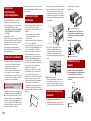
Before installing
For AVIC-Z920DAB and AVIC-
Z820DAB users
Installation notes
Leave ample
space
5 cm
5 cm
Do not cover this area.
• The semiconductor laser will be damaged
if it overheats, so don’t install this product
anywhere hot- for instance, near a heater
outlet.
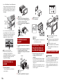
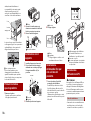
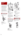
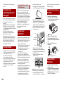
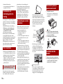
1 Remove the trim ring.
Extend top and bottom of the trim ring
outwards to remove the trim ring.
Trim ring
2 Insert the supplied extraction keys
into both sides of the unit until they
click into place.
3 Pull the unit out of the holder.
Extraction key
1 Install the holder into the dashboard.
2 Secure the mounting sleeve by using a
screwdriver to bend the metal tabs
(90°) into place.
Dashboard
Holder
3 Install this product into the holder.
Dashboard
4 Attach the trim ring.
Trim ring
Before installing this
product
Installation with the
holder
112 mm
182 mm

10En
Groove
Attach the trim ring with the side
with a groove facing downward.
1 Fastening this product to the factory
radio-mounting bracket.
Position this product so that its screw
holes are aligned with the screw holes
of the bracket, and tighten the screws at
three locations on each side.
Use either the truss head screws or flush
surface screws, depending on the shape
of the bracket’s screw holes.
Factory radio-mounting bracket
If the pawl interferes with
installation, you may bend it down
out of the way.
Dashboard or console
Truss head screw or flush surface
screw
Be sure to use the screws supplied
with this product.
CAUTION
Do not cut the GPS aerial lead to shorten it
or use an extension to make it longer.
Altering the aerial cable could result in a
short circuit or malfunction and
permanent damage to this product.
• The aerial should be installed on a level
surface where radio waves will be
blocked as little as possible. Radio waves
cannot be received by the aerial if
reception from the satellite is blocked.
Dashboard
Rear shelf
• When installing the GPS aerial inside the
vehicle, be sure to use the metal sheet
provided with your system. If this is not
used, the reception sensitivity will be
poor.
• Do not cut the accessory metal sheet.
This would reduce the sensitivity of the
GPS aerial.
• Take care not to pull the aerial lead when
removing the GPS aerial. The lead may
become detached.
Installation using the screw
holes on the side of this
product
Installing the GPS
aerial
Installation notes
• Do not paint the GPS aerial, as this may
affect its performance.

11En
English
WARNING
Do not install the GPS aerial over any sensors or vents on the dashboard of the vehicle, as
doing so may interfere with the proper functioning of such sensors or vents and may
compromise the ability of the metal sheet under the GPS aerial to properly and securely
affix to the dashboard.
GPS aerial
Metal sheet
Peel off the protective sheet on the rear.
Double-sided tape
Clamps
Use clamps to secure the lead where necessary inside the vehicle.
NOTES
• Affix the metal sheet on the surface as level as possible where the GPS aerial faces the
window.
• Affix the GPS aerial on the metal sheet using the double-sided tape.
• The metal sheet contains a strong adhesive which may leave a mark on the surface if it is
removed.
• When attaching the metal sheet, do not cut it into small pieces.
• Some models use window glass that does not allow signals from GPS satellites to pass
through. On such models, install the GPS aerial on the outside of the vehicle.
When installing the aerial inside the vehicle (on the dashboard or rear
shelf)
Make sure the surface is free of
moisture, dust, grime, oil, etc.,
before affixing the metal sheet.
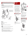
• Install the microphone in a place where
its direction and distance from the driver
make it easiest to pick up the driver’s
voice.
• Be sure to turn off (ACC OFF) the product
before connecting the microphone.
• Depending on the vehicle model, the
microphone cable length may be too
short when you mount the microphone
on the sun visor. In such cases, install the
microphone on the steering column.
1 Fit the microphone lead into the
groove.
Microphone lead
Groove
2 Attach the microphone clip to the sun
visor.
Microphone clip
Clamps
Use separately sold clamps to secure
the lead where necessary inside the
vehicle.
Install the microphone on the sun visor
when it is in the up position. It cannot
recognise the driver’s voice if the sun
visor is in the down position.
1 Detach the microphone base from the
microphone clip by sliding the
microphone base while pressing the
tab.
Tab
Microphone base
2 Mount the microphone on the
steering column.
Installing the
microphone
Mounting on the sun visor
Installation on the steering
column

12En
Double-sided tape
Clamps
Use separately sold clamps to secure
the lead where necessary inside the
vehicle.
NOTE
Install the microphone on the steering
column, keeping it away from the steering
wheel.
The microphone angle can be adjusted.
Adjusting the microphone angle
1 Reconnect the negative (-) terminal of
the vehicle’s battery.
First, double-check that all connections
are correct and that this product is
installed correctly. Reassemble all
vehicle components that you previously
removed. Then reconnect the negative
(-) cable to the negative (-) terminal of
the battery.
2 Start the engine.
3 Press the RESET button.
Press the RESET button on this product
with a pointed object such as the tip of
a pen.
• Some of the settings and recorded
contents will not be reset.
4 Change the settings as desired.
• For details concerning operations,
refer to Operation Manual.
5 Drive down an unobstructed road
until the GPS starts receiving the
signal normally.
NOTE
After installing this product, be sure to
check at a safe place that the vehicle is
performing normally.
After installation
After installing this
product
Z920DAB
Z820DAB
Z720DAB
Z620BT
Z7210DAB
Z6210BT

13En
English

2Fr
• Les fonctions de navigation de ce produit
(et la caméra de recul en option, si vous
en possédez une) sont uniquement
destinées à vous assister lors de la
conduite de votre véhicule. Elles ne
remplacent pas votre vigilance,
appréciation et prudence lorsque vous
conduisez.
• N’utilisez jamais ce produit pour vous
rendre à l’hôpital, à un commissariat, ou
dans d’autres lieux similaires en cas
d’urgence. Veuillez composer le numéro
d’appel des urgences approprié.
• Veillez à ne pas utiliser ce produit, les
applications ou la caméra de recul en
option (si vous en possédez une), car cela
risquerait de vous distraire et de
compromettre votre sécurité à bord du
véhicule. Veillez à toujours respecter les
règles de conduite sécuritaire et la
réglementation en vigueur en matière de
circulation routière. Si vous avez des
difficultés à utiliser ce produit, garez votre
véhicule dans un endroit sûr et serrez le
frein de stationnement avant d’effectuer
les réglages nécessaires.
• Ce manuel vous explique comment
installer ce produit dans votre véhicule.
L’utilisation de ce produit est expliquée
dans les autres manuels.
• N’installez pas ce produit dans un endroit
où il est susceptible
(i) de gêner la vision du conducteur,
(ii) d’empêcher le déclenchement ou
l’utilisation des systèmes de sécurité,
notamment des airbags ou des feux de
détresse, ou
(iii) d’empêcher le conducteur d’utiliser le
véhicule en toute sécurité.
Dans certains cas, il peut être impossible
d’installer ce produit selon le type de
véhicule ou la forme de son habitacle.
• Les icônes du modèle qui figurent dans
ce manuel montrent que la description
est destinée aux modèles indiqués par les
icônes. Si l’icône suivant s’affiche, la
description s’applique uniquement au
modèle indiqué.
ex.)
ATTENTION
Pioneer vous déconseille d’installer vous-
même ce produit. Ce produit doit être
installé par un professionnel. Pour installer
et configurer ce produit, nous vous
recommandons de faire appel à un
technicien agréé Pioneer, qui possède les
compétences et l’expérience nécessaires
en matière d’électronique mobile. VEILLEZ
À NE JAMAIS RÉPARER VOUS-MÊME CE
PRODUIT. L’installation ou la réparation de
ce produit et de ses câbles de connexion
peut vous exposer à un risque de décharge
électrique ou à d’autres dangers, et peut
entraîner des dommages non couverts par
la garantie.
• Veuillez lire ce manuel entièrement et
attentivement avant d’installer ce
produit.
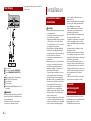
Connexion
Précautions
Votre nouveau produit et le
guide qui l’accompagne
Précautions
importantes
Z000DAB
• Conservez ce manuel à portée de main si
vous souhaitez le consulter
ultérieurement.
• Portez une grande attention à l’ensemble
des avertissements dans ce manuel et
suivez bien les instructions.
• Dans certaines situations, il est possible
que ce produit affiche une position
inexacte de votre véhicule, de la distance
des objets à l’écran et de la boussole qui
indique les directions. Par ailleurs, le
système présente certaines limites,
notamment l’incapacité d’identifier les
rues à sens unique, les restrictions
temporaires de la circulation et les zones
de circulation potentiellement à risque.
Veuillez faire preuve de bon sens en
fonction des conditions de circulation
réelles.
• Comme avec tout accessoire dans votre
véhicule, ce produit ne doit pas vous
gêner et compromettre votre sécurité à
bord du véhicule, au risque d’entraîner
des dommages corporels graves, voire la
mort. Si vous éprouvez des difficultés à
utiliser le système ou à lire l’écran, veuillez
effectuer des réglages tout en étant
stationné dans un lieu sûr.
• N’oubliez pas d’attacher votre ceinture de
sécurité avant de conduire votre véhicule.
En cas d’accident, le port de la ceinture de
sécurité peut réduire considérablement
la gravité des blessures.
• Certaines lois nationales ou
gouvernementales peuvent interdire ou
restreindre l’emplacement et l’utilisation
de ce produit dans votre véhicule.
Veuillez vous conformer à toutes les lois
et réglementations en vigueur
concernant l’utilisation, l’installation et le
fonctionnement de ce produit.
ATTENTION
N’essayez pas de manipuler ou de
désactiver le système de verrouillage du
frein de stationnement mis en place pour
votre sécurité. Toute manipulation ou
désactivation du système de verrouillage
du frein de stationnement risque
d’entraîner des dommages corporels
graves, voire la mort.
PRÉCAUTION
• Si vous décidez d’effectuer l’installation
vous-même, et que vous avez suivi une
formation spécifique ou que vous savez
installer des dispositifs électroniques
mobiles, veuillez bien suivre toutes les
étapes décrites dans le manuel
d’installation.
• Fixez tous les câbles à l’aide de serre-
câbles ou de ruban isolant. Ne laissez
aucun fil dénudé apparent.
• Ne raccordez pas directement le fil jaune
de ce produit à la batterie du véhicule. Si
vous raccordez ce fil directement à la
batterie, les vibrations du moteur
risquent de détériorer l’isolant au point
où le fil passe de l’habitacle au
compartiment moteur. Si l’isolant du fil
jaune venait à se rompre au contact de
pièces métalliques, un court-circuit
risquerait de se produire et de mettre en
danger le conducteur et les passagers.
• Il est extrêmement dangereux de laisser
les câbles s’enrouler autour du volant ou
du levier de vitesses. Veillez à installer ce
produit, ses câbles et ses fils de telle sorte
qu’ils ne gênent pas la conduite.
• Assurez-vous que les fils et les câbles ne
gêneront pas le mouvement des parties
mobiles du véhicule (notamment le
volant, le levier de vitesses, le frein de
Précautions avant de
connecter le système

3Fr
Français
stationnement, les rails coulissants des
sièges, les portières ou toute autre
commande du véhicule) ou ne se
coinceront pas dedans.
• N’acheminez pas les fils dans des endroits
soumis à des températures élevées. La
chaleur générée risque de chauffer
l’isolant et d’endommager les fils, ce qui
peut provoquer un court-circuit ou un
dysfonctionnement et entraîner des
dommages irréversibles.
• Ne coupez pas le câble d’antenne GPS
pour le raccourcir ou n’utilisez pas
d’extension pour le rallonger. Modifier le
câble d’antenne risque de provoquer un
court-circuit ou un dysfonctionnement.
• Ne raccourcissez aucun fil. Le cas échéant,
le circuit de protection (porte-fusibles,
résistance ou filtre de protection, etc.)
risque de ne pas fonctionner
correctement.
• Veillez à ne jamais couper l’isolant du fil
d’alimentation de ce produit en vue
d’utiliser ce fil pour alimenter d’autres
produits électroniques. Cela risque
d’entraîner le dépassement de la capacité
nominale du fil et de provoquer une
surchauffe.
• Utilisez ce produit avec une batterie de
12 volts et une mise à la terre du pôle
négatif uniquement. Dans le cas
contraire, un dysfonctionnement ou un
incendie risque de se produire.
• Pour éviter les courts-circuits dans le
système électrique, veillez à débrancher
le câble (–) de la batterie avant de
procéder à l’installation.
ATTENTION
• Utilisez des haut-parleurs de plus de 50 W
(puissance maximale en entrée) et dont la
valeur d’impédance est comprise entre
4 Ω et 8 Ω. N’utilisez pas de haut-parleurs
dont la valeur d’impédance est comprise
entre 1 Ω et 3 Ω avec cet appareil.
• Le fil noir est le fil de mise à la terre.
Mettez-le à la terre séparément des
produits à courant élevé tels que les
amplificateurs de puissance. Évitez de
raccorder plusieurs produits à la terre
d’un autre produit. Par exemple, chaque
amplificateur de puissance doit être mis à
la terre séparément de la masse de ce
produit. Le raccordement de plusieurs
masses risque de provoquer un incendie
et/ou d’endommager les produits si les
fils de mise à la terre sont déconnectés.
• Lors du remplacement du fusible, utilisez
uniquement un fusible respectant
l’intensité indiquée sur le produit.
• Lorsque vous débranchez un connecteur,
ne tirez que sur le connecteur. Ne tirez
pas le fil, car vous pourriez le déloger du
connecteur.
• Il est impossible d’installer ce produit
dans un véhicule dont l’interrupteur
d’allumage ne dispose pas d’une position
ACC (accessoire).
Avant d’installer ce
produit
Pour éviter les
dommages
• Pour éviter les courts-circuits, couvrez le
fil de déconnexion de ruban isolant. Il est
particulièrement important d’isoler tous
les fils de haut-parleur non utilisés ; si ces
fils restent dénudés, ils risquent de
provoquer un court-circuit.
• Fixez les connecteurs de même couleur
sur le port de couleur correspondante,
ex., le connecteur bleu sur le port bleu, le
noir sur le noir, etc.
• Pour raccorder des amplificateurs de
puissance ou d’autres appareils à ce
produit, reportez-vous au manuel de
l’appareil à raccorder.
• Un circuit BPTL unique étant utilisé, ne
mettez pas directement le coté du fil du
haut-parleur à la terre ou raccordez
ensemble le côté avec l’autre côté du fil
du haut-parleur . Veillez à raccorder le
côté du fil du haut-parleur avec le côté
du fil du haut-parleur sur ce produit.
• Le symbole graphique situé sur le
produit représente le courant continu.
• Lorsque vous allumez le moteur
(interrupteur d’allumage en position ACC
ON), un signal de commande est transmis
via le fil bleu/blanc. Raccordez ce fil à la
borne de commande à distance d’un
amplificateur de puissance externe, à la
borne de commande du relais de
l’antenne automatique ou à la borne de
commande d’alimentation de
l’amplificateur d’antenne (max. 300 mA
12 V c.c.). Le signal de commande est
transmis via le fil bleu/blanc, même si la
source audio est désactivée.
• Assurez-vous de ne pas utiliser ce fil
comme le fil d’alimentation pour les
amplificateurs de puissance externe. Ce
branchement pourrait entraîner une
charge indue et des dysfonctionnements.
• Assurez-vous de ne pas utiliser ce fil
comme le fil d’alimentation pour
l’antenne automatique ou l’amplificateur
d’antenne. Ce branchement pourrait
entraîner une charge indue et des
dysfonctionnements.
Important
Lorsque ce produit est en mode [Power
OFF], le signal de commande est
également désactivé. Si le mode [Power
OFF] est annulé, le signal de commande est
à nouveau émis, et l’antenne sort à l’aide
de la fonction d’antenne automatique (si
l’antenne est utilisée). Veillez à ce que
l’antenne sortie évite tout contact avec un
obstacle.
ATTENTION
• Pour éviter le risque d’accident et une
violation éventuelle des lois applicables,
vous ne devez jamais utiliser ce produit
tout en conduisant, sauf à des fins de
navigation. Par ailleurs, les écrans arrière
ne doivent pas se trouver dans un endroit
qui peut gêner le conducteur.
• Dans certains pays, il peut être illégal
pour le conducteur autant que pour les
passagers de regarder des images vidéo
sur un écran installé à l’intérieur du
véhicule. Dans ce cas, vous devez
respecter les lois en vigueur et ne pas
utiliser la source vidéo sur ce produit.
Remarque concernant
le fil bleu/blanc
Position ACC
Pas de position ACC
Panneau arrière
(bornes principales)

4Fr
Antenne GPS 3,55 m
Microphone 3 m
Câble de conversion de Bus véhicule
13 cm*.
Référez-vous au mode d’emploi pour
l’adaptateur de Bus véhicule (vendu
séparément).
Entrée d’antenne radio numérique*
Ce produit
Prise d’antenne
Câble AV d’entrée/sortie
Alimentation
Fusible (10 A)
Entrée de la télécommande câblée
Il est possible de raccorder un
adaptateur de télécommande (vendu
séparément).
*AVIC-Z920DAB/AVIC-Z820DAB/AVIC-
Z720DAB/AVIC-Z7210DAB
PRÉCAUTION
Pour améliorer la réception de la radio
numérique, utilisez une antenne radio
numérique munie d’une entrée
d’alimentation fantôme (de type actif).
Pioneer recommande d’utiliser AN-DAB1
ou CA-AN-DAB.001 (vendu séparément). La
consommation électrique de l’antenne
radio numérique ne doit pas dépasser
100 mA.
ATTENTION
TOUTE CONNEXION INCORRECTE
RISQUE D’ENTRAÎNER DES DOMMAGES
ET MATÉRIELS GRAVES, NOTAMMENT
UNE DÉCHARGE ÉLECTRIQUE ET DES
INTERFÉRENCES AVEC L’UTILISATION DU
SYSTÈME D’ANTIBLOCAGE DES ROUES
(ABS) DU VÉHICULE, DE LA
TRANSMISSION AUTOMATIQUE ET
D’INDICATION DE LA VITESSE.
PRÉCAUTION
Il vous est fortement recommandé de
raccorder le fil d’impulsion vitesse afin
d’obtenir une précision de navigation et de
meilleurs résultats.
Câble d’alimentation
À l’alimentation
Selon le type de véhicule, la fonction de
2* et 4* peut différer. Dans ce cas, veillez
à raccorder 1* à 4* et 3* à 2*.
Jaune (2*)
Secours (ou accessoire)
Jaune (1*)
Sur la borne alimentée quelle que soit la
position du commutateur d’allumage.
Rouge (4*)
Accessoire (ou secours)
Rouge (3*)
À raccorder à la borne commandée par
l’interrupteur d’allumage (12 V c.c.).
Raccordez ensemble les fils de même
couleur.
Orange/blanc
À la borne de l’interrupteur d’éclairage.
Noir (terre)
À la carrosserie (métal) du véhicule.
Bleu/blanc (5*)
La position des broches du connecteur
ISO peut différer selon le type de
véhicule. Raccordez 5* et 6* lorsque la
broche 5 est un type de commande
d’antenne. Dans un autre type de
véhicule, ne connectez jamais 5* et 6*.
Bleu/blanc (6*)
Raccordez à la borne de commande du
relais d’antenne automatique (max.
300 mA 12 V c.c.).
Bleu/blanc
À raccorder à la borne de commande
système de l’amplificateur de puissance
(max. 300 mA 12 V c.c.).
Violet/blanc
Une fois raccordés, ce produit peut
détecter si le véhicule avance ou recule.
Raccordez le fil violet/blanc avec le fil
dont la tension change lorsque le levier
de vitesses est enclenché en marche
arrière. S’il n’est pas raccordé, le capteur
ne peut pas bien détecter si votre
véhicule avance ou recule. Ainsi, la
position de votre véhicule détectée par
le capteur peut être mal alignée avec la
position réelle.
Lorsque vous utilisez une caméra de
recul, veuillez vous assurer de la
raccorder à ce fil. Sinon, vous ne pourrez
pas basculer sur les images de la caméra
de recul.
Rose (ENTRÉE DU SIGNAL DE LA VITESSE
DU VÉHICULE)
Ce produit est raccordé ici pour détecter
la distance effectuée par le véhicule.
Raccordez toujours le circuit de
détection de vitesse du véhicule. Ne pas
le raccorder augmentera les erreurs lors

5Fr
Français
de l’affichage de l’emplacement du
véhicule.
Vert clair
Ce fil permet de détecter l’état de
marche/arrêt du frein de
stationnement. Ce fil doit être raccordé
au côté de l’alimentation du contacteur
du frein de stationnement.
Si ce raccordement est mal fait ou
omis, vous ne pourrez pas utiliser
certaines fonctions de ce produit.
Méthode de connexion
Raccordez le fil (1), puis fixez fermement
les pinces à becs fins (2).
Côté de l’alimentation
Contacteur du frein de stationnement
Côté terre
Fils des haut-parleurs
Blanc : Avant gauche + ou aigus gauche
+
Blanc/noir : Avant gauche – ou aigus
gauche –
Gris : Avant droit + ou aigus droit +
Gris/noir : Avant droit – ou aigus droit –
Vert : Arrière gauche + ou médiums
gauche +
Vert/noir : Arrière gauche – ou médiums
gauche –
Violet : Arrière droit + ou médiums droit
+
Violet/noir : Arrière droit – ou médiums
droit –
Connecteur ISO
Dans certains véhicules, le connecteur
ISO peut être divisé en deux. Dans ce
cas, veillez à le raccorder aux deux
connecteurs.
REMARQUES
• La position du circuit de détection de
vitesse et la position du contacteur du
frein de stationnement varient en
fonction du modèle du véhicule. Pour
plus de détails, contactez votre
revendeur Pioneer agréé ou un
installateur professionnel.
• Lorsque vous raccordez un haut-parleur
d’extrêmes-graves à ce produit plutôt
qu’un haut-parleur arrière, modifiez le
réglage de sortie arrière lors de la
configuration initiale. La sortie du haut-
parleur d’extrêmes-graves de ce produit
est monophonique.
• Lorsque vous utilisez un haut-parleur
d’extrêmes-graves de 2 Ω, veillez à le
raccorder aux fils violet et violet/noir de
cet appareil. Ne branchez aucun appareil
aux fils vert et vert/noir.
Important
Les fils de haut-parleur ne sont pas utilisés lors de l’utilisation de cette connexion.
Sortie du haut-parleur d’extrêmes graves (SUBWOOFER OUTPUT) 23 cm (STD)
Sortie des graves (NW)
Câble RCA (vendu séparément)
Amplificateur de puissance
Sortie avant (FRONT OUTPUT) 15 cm (STD)
Sortie des aigus (NW)
Sortie arrière (REAR OUTPUT) 15 cm (STD)
Amplificateur de puissance (vendu séparément)

6Fr
Sortie des médiums (NW)
Jaune/noir (MUTE)
Si vous utilisez un équipement muni d’une fonction de désactivation du son, branchez
ce fil au fil de désactivation du son de cet équipement. Dans le cas contraire, ne
raccordez pas le fil de désactivation du son.
Ce produit
Télécommande du système
Raccordez au câble bleu/blanc (max. 300 mA 12 V c.c).
Haut-parleur arrière (STD)
Haut-parleur de médiums (NW)
Haut-parleur avant (STD)
Haut-parleur d’aigus (NW)
Haut-parleur d’extrêmes-graves (STD)
Haut-parleur de graves (NW)
REMARQUES
• Sélectionnez le mode de haut-parleur approprié, à savoir le mode standard (STD) ou le
mode réseau (NW). Pour en savoir plus, consultez le manuel d’utilisation.
• Une source audio sera paramétrée en mode Silencieux ou Son réduit, alors que les sons
suivants ne seront pas coupés ou diminués. Pour en savoir plus, consultez le manuel
d’utilisation.
–Guidage vocal de la navigation
–La sonnerie et la voix entrante du téléphone portable qui est connecté à ce produit via la
technologie sans fil Bluetooth
REMARQUES
• Pour en savoir plus sur le mode de
connexion d’un périphérique externe à
l’aide d’un câble vendu séparément,
consultez le manuel qui accompagne ce
câble.
• Pour en savoir plus sur la connexion,
l’utilisation et la compatibilité du iPhone,
consultez le manuel d’utilisation.
• Pour en savoir plus sur la connexion et
l’utilisation d’un smartphone, consultez
le manuel d’utilisation.
Apposez les étiquettes d’identification sur
les câbles USB avant d’installer ce produit
dans un véhicule.
1 Raccordez les câbles USB aux USB
ports 1 et 2 à l’arrière de ce produit.
2 Apposez les étiquettes d’identification
correspondantes à chaque port sur les
câbles USB tel qu’illustré ci-dessous.
Apposez l’étiquette « Port 1 Apple
CarPlay » sur le câble USB raccordé au
port 1 USB.
Apposez l’étiquette « Port 2 » ou « Port 2
Android Auto » sur le câble USB
raccordé au port 2 USB.
Port 1 USB
Câble USB de 1,5 m
Câble d’interface USB pour iPod/iPhone
(CD-IU52) (vendu séparément)
iPhone
iPod/iPhone et
smartphone
Apposer les étiquettes
d’identification sur les
câbles USB
iPod/iPhone
Raccordement via le port USB

7Fr
Français
Port 2 USB
Câble USB de 1,5 m
Câble USB - micro USB (de type USB A -
micro USB B) (fourni avec CD-MU200)
Smartphone
Lorsque vous utilisez la caméra de recul, les
images vidéo sont automatiquement
remplacées par celle de la caméra de recul
dès que vous enclenchez la marche arrière
REVERSE (R). Le mode Vue Caméra vous
permet également de contrôler les objets
derrière vous lorsque vous conduisez.
ATTENTION
UTILISEZ CETTE ENTRÉE UNIQUEMENT
POUR REPRODUIRE LES IMAGES DE LA
CAMÉRA DE RECUL. TOUTE AUTRE
UTILISATION RISQUE D’ENTRAÎNER DES
DOMMAGES MATÉRIELS OU CORPORELS.
PRÉCAUTION
• L’image affichée à l’écran peut être
inversée.
• La caméra de recul vous permet de
contrôler les véhicules remorqués ou de
vous garer dans un endroit étroit. Ne
l’utilisez pas à des fins de divertissement.
• Les objets à l’arrière peuvent vous
sembler plus proches ou plus éloignés
qu’ils ne le sont en réalité.
• En mode plein écran, les images affichées
lorsque vous faites marche arrière ou
lorsque vous contrôlez les objets à
l’arrière du véhicule peuvent légèrement
différer.
Ce produit
Alimentation
Câble d’alimentation
Violet/blanc (REVERSE-GEAR SIGNAL
INPUT)
Marron (REAR VIEW CAMERA IN) 23 cm
Jaune (VIDEO INPUT) 23 cm
Caméra de recul (ND-BC8) (vendue
séparément)
À la sortie vidéo
Câble RCA (fourni avec ND-BC8)
Smartphone
(périphérique Android™)
Raccordement via le port USB
Caméra
Câble RCA (vendu séparément)
Caméra de vision (vendue séparément)
REMARQUES
• Raccordez uniquement la caméra de
recul au câble marron. Ne raccordez
aucun autre équipement.
• Certains réglages sont requis pour utiliser
la caméra de recul. Pour en savoir plus,
consultez le manuel d’utilisation.
Ce produit
Rouge, blanc (AUDIO INPUT) 23 cm
Jaune (VIDEO INPUT) 23 cm
Câble RCA (vendu séparément)
À l’entrée audio
À l’entrée vidéo
Composant vidéo externe (vendu
séparément)
REMARQUE
Le réglage approprié est requis pour
utiliser un composant vidéo externe. Pour
en savoir plus, consultez le manuel
d’utilisation.
Ce produit
Câble AV avec mini-prise (vendu
séparément)
Entrée AUX (AUX IN) 15 cm
Jaune
Rouge, blanc
Composant vidéo externe
Utiliser l’entrée AV
Utiliser une entrée AUX

8Fr
Câbles RCA (vendus séparément)
À la sortie vidéo
Aux sorties audio
Composant vidéo externe (vendu
séparément)
REMARQUE
Le réglage approprié est requis pour
utiliser un composant vidéo externe. Pour
en savoir plus, consultez le manuel
d’utilisation.
PRÉCAUTION
Veillez à utiliser un câble AV mini-jack
(vendu séparément) pour le raccordement.
Si vous utilisez d’autres câbles, la position
de raccordement pourra différer selon les
images et les sons déformés.
Ce produit
Port HDMI
Câble HDMI™ haut-débit (vendu
séparément)
Dispositif HDMI (vendu séparément)
REMARQUE
Lorsque vous raccordez le câble HDMI™
haut-débit, utilisez le verrou pour le fixer
en toute sécurité (page 8).
Veillez à fixer le câble HDMI™ haut-débit à
l’aide du verrou, lorsque vous raccordez le
dispositif externe avec le câble HDMI™
haut-débit.
1 Insérez le câble HDMI™ haut-débit
dans le port HDMI.
2 Enroulez le verrou autour de la boucle
au-dessus du port HDMI et du câble
HDMI™ haut-débit, puis serrez-le pour
fixer le câble HDMI™ haut-débit.
Utiliser une entrée HDMI
L: Audio gauche
(blanc)
R : Audio droit
(rouge)
V: Vidéo (jaune)
G: Terre
Z920DAB
Fixer le câble HDMI™
haut-débit
Z920DAB
Boucle
Verrou
Câble HDMI™ haut-débit
PRÉCAUTION
Ne serrez pas le verrou plus qu’il ne faut.
Ce produit
Sortie audio arrière (R. AUDIO OUT)
Jaune (REAR MONITOR OUTPUT)
30 cm
Câble mini à broche (vendu
séparément)
Câbles RCA (vendus séparément)
À l’entrée audio
À l’entrée vidéo
Écran arrière avec prises d’entrée RCA
(vendu séparément)
ATTENTION
Veillez à ne JAMAIS installer l’écran arrière
dans un endroit où le conducteur est
susceptible de regarder la source vidéo
tout en conduisant.
La borne de sortie vidéo arrière du produit
permet de raccorder un écran afin que les
passagers arrière puissent regarder la
source vidéo.
Affichage arrière
La pagina si sta caricando...
La pagina si sta caricando...
La pagina si sta caricando...
La pagina si sta caricando...
La pagina si sta caricando...
La pagina si sta caricando...
La pagina si sta caricando...
La pagina si sta caricando...
La pagina si sta caricando...
La pagina si sta caricando...
La pagina si sta caricando...
La pagina si sta caricando...
La pagina si sta caricando...
La pagina si sta caricando...
La pagina si sta caricando...
La pagina si sta caricando...
La pagina si sta caricando...
La pagina si sta caricando...
La pagina si sta caricando...
La pagina si sta caricando...
La pagina si sta caricando...
La pagina si sta caricando...
La pagina si sta caricando...
La pagina si sta caricando...
La pagina si sta caricando...
La pagina si sta caricando...
La pagina si sta caricando...
La pagina si sta caricando...
La pagina si sta caricando...
La pagina si sta caricando...
La pagina si sta caricando...
La pagina si sta caricando...
La pagina si sta caricando...
La pagina si sta caricando...
La pagina si sta caricando...
La pagina si sta caricando...
La pagina si sta caricando...
La pagina si sta caricando...
La pagina si sta caricando...
La pagina si sta caricando...
La pagina si sta caricando...
La pagina si sta caricando...
La pagina si sta caricando...
La pagina si sta caricando...
La pagina si sta caricando...
La pagina si sta caricando...
La pagina si sta caricando...
La pagina si sta caricando...
La pagina si sta caricando...
La pagina si sta caricando...
La pagina si sta caricando...
La pagina si sta caricando...
La pagina si sta caricando...
La pagina si sta caricando...
La pagina si sta caricando...
La pagina si sta caricando...
-
 1
1
-
 2
2
-
 3
3
-
 4
4
-
 5
5
-
 6
6
-
 7
7
-
 8
8
-
 9
9
-
 10
10
-
 11
11
-
 12
12
-
 13
13
-
 14
14
-
 15
15
-
 16
16
-
 17
17
-
 18
18
-
 19
19
-
 20
20
-
 21
21
-
 22
22
-
 23
23
-
 24
24
-
 25
25
-
 26
26
-
 27
27
-
 28
28
-
 29
29
-
 30
30
-
 31
31
-
 32
32
-
 33
33
-
 34
34
-
 35
35
-
 36
36
-
 37
37
-
 38
38
-
 39
39
-
 40
40
-
 41
41
-
 42
42
-
 43
43
-
 44
44
-
 45
45
-
 46
46
-
 47
47
-
 48
48
-
 49
49
-
 50
50
-
 51
51
-
 52
52
-
 53
53
-
 54
54
-
 55
55
-
 56
56
-
 57
57
-
 58
58
-
 59
59
-
 60
60
-
 61
61
-
 62
62
-
 63
63
-
 64
64
-
 65
65
-
 66
66
-
 67
67
-
 68
68
-
 69
69
-
 70
70
-
 71
71
-
 72
72
-
 73
73
-
 74
74
-
 75
75
-
 76
76


Pioneer AVIC Z620 BT Manuale utente
- Categoria
- Subwoofer
- Tipo
- Manuale utente
- Questo manuale è adatto anche per
in altre lingue
- français: Pioneer AVIC Z620 BT Manuel utilisateur
- español: Pioneer AVIC Z620 BT Manual de usuario
- Deutsch: Pioneer AVIC Z620 BT Benutzerhandbuch
- Nederlands: Pioneer AVIC Z620 BT Handleiding
Documenti correlati
-
Pioneer SPH-EVO64DAB Guida d'installazione
-
Pioneer AVH-Z9100DAB Guida d'installazione
-
Pioneer AVH-Z7100DAB Guida d'installazione
-
Pioneer AVH-A7100BT Manuale del proprietario
-
Pioneer SPH-DA250DAB Guida d'installazione
-
Pioneer AVIC-Z610BT Guida d'installazione
-
Mode AVIC Z7330 DAB Manuale utente
-
Mode AVIC-F950 Manuale del proprietario
-
-
Pioneer AVIC F80 DAB Guida d'installazione

