HOTPOINT/ARISTON BWMD 742 (EU) Guida utente
- Categoria
- Lavatrici
- Tipo
- Guida utente

GB
1
Contents
Installation, 2-3-4-5
Unpacking and levelling
Connecting the electricity and water supplies
The first wash cycle
Technical data
Instructions for the fitter
Description of the washing machine, 6-7
Control panel
Display
Running a wash cycle, 8
Wash cycles and functions, 9
Table of wash cycles
Wash functions
Detergents and laundry, 10
Detergent dispenser drawer
Preparing the laundry
Special wash cycles
Load balancing system
Precautions and tips, 11
General safety
Disposal
Opening the porthole door manually
Care and maintenance, 12
Cutting off the water or electricity supply
Cleaning the washing machine
Cleaning the detergent dispenser drawer
Caring for the door and drum of your appliance
Cleaning the pump
Checking the water inlet hose
Troubleshooting, 13
Service, 14
BWMD 742
Instructions for use
WASHING MACHINE
English,1
GB
ES
Español,29Italiano,15
I
Русский,43
CIS
DE
Deutsch,57

2
GB
! This instruction manual should be kept in a safe place for
future reference. If the washing machine is sold, transferred
or moved, make sure that the instruction manual remains
with the machine so that the new owner is able to familiari-
se himself/herself with its operation and features.
! Read these instructions carefully: they contain vital infor-
mation relating to the safe installation and operation of the
appliance.
Unpacking and levelling
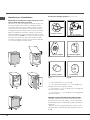
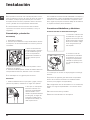
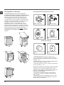
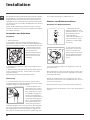
Unpacking
1. Remove the washing machine from its packaging.
2. Make sure that the washing machine has not been
damaged during the transportation process. If it has been
damaged, contact the retailer and do not proceed any
further with the installation process.
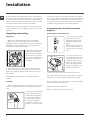
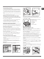
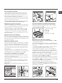
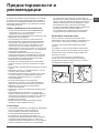
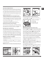
3. Remove the 4 protective
screws (used during tran-
sportation) and the rubber
washer with the correspon-
ding spacer, located on the
rear part of the appliance
(see figure).
4. Close off the holes using the plastic plugs provided.
5. Keep all the parts in a safe place: you will need them
again if the washing machine needs to be moved to ano-
ther location.
! Packaging materials should not be used as toys for
children.
Levelling
1. Install the washing machine on a flat sturdy floor, without
resting it up against walls, furniture cabinets or anything
else.
2. If the floor is not perfectly
level, compensate for any
unevenness by tightening
or loosening the adjusta-
ble front feet (see figure);
the angle of inclination,
measured in relation to the
worktop, must not exceed
2°.
Levelling the machine correctly will provide it with stability,
help to avoid vibrations and excessive noise and prevent it
from shifting while it is operating. If it is placed on carpet or
a rug, adjust the feet in such a way as to allow a sufficient
ventilation space underneath the washing machine.
Connecting the electricity and water
supplies
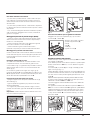
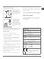
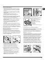
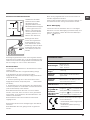
Connecting the water inlet hose
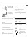
1. Connect the supply pipe
by screwing it to a cold
water tap using a ¾ gas
threaded connection (see
figure).
Before performing the con-
nection, allow the water to
run freely until it is perfectly
clear.
2. Connect the inlet hose
to the washing machine by
screwing it onto the corre-
sponding water inlet of the
appliance, which is situa-
ted on the top right-hand
side of the rear part of the
appliance (see figure).
3. Make sure that the hose is not folded over or bent.
! The water pressure at the tap must fall within the values
indicated in the Technical details table (see next page).
! If the inlet hose is not long enough, contact a specialised
shop or an authorised technician.
! Never use second-hand hoses.
! Use the ones supplied with the machine.
Installation

GB
3
Connecting the drain hose
Connect the drain hose,
without bending it, to a drai-
nage duct or a wall drain
located at a height between
65 and 100 cm from the
floor;
alternatively, rest it on
the side of a washbasin
or bathtub, fastening the
duct supplied to the tap
(see figure). The free end
of the hose should not be
underwater.
! We advise against the use of hose extensions; if it is
absolutely necessary, the extension must have the same
diameter as the original hose and must not exceed 150 cm
in length.
Electrical connections
Before plugging the appliance into the electricity socket,
make sure that:
• the socket is earthed and complies with all applicable
laws;
• the socket is able to withstand the maximum power load
of the appliance as indicated in the Technical data table
(see opposite);
• the power supply voltage falls within the values indicated
in the Technical data table (see opposite);
• the socket is compatible with the plug of the washing
machine. If this is not the case, replace the socket or the
plug.
! The washing machine must not be installed outdoors,
even in covered areas. It is extremely dangerous to leave
the appliance exposed to rain, storms and other weather
conditions.
! When the washing machine has been installed, the elec-
tricity socket must be within easy reach.
! Do not use extension cords or multiple sockets.
! The cable should not be bent or compressed.
! The power supply cable must only be replaced by autho-
rised technicians.
Warning! The company shall not be held responsible in the
event that these regulations are not respected.
The first wash cycle
Once the appliance has been installed, and before you use
it for the first time, run a wash cycle with detergent and no
laundry, using the wash cycle (60°C).
65 - 100 cm
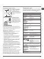
Technical data
Model
BWMD 742
Dimensions
width 59.5 cm
height 81.5 cm
depth 54.5 cm
Capacity
from 1 to 7 kg
Electrical
connections
please refer to the technical data plate
fixed to the machine
Water connections
maximum pressure 1 MPa (10 bar)
minimum pressure 0.05 MPa (0.5 bar)
drum capacity 52 litres
Spin speed
up to 1400 rotations per minute
Test wash cycles
in accordance
with directives
1061/2010 and
1015/2010
programme
(60°) (1st press of the button);
Standard Cotton 60°C.
programme (40°) (2nd press of the button);
Standard Cotton 40°C.
This appliance conforms to the following
EC Directives:
- 2004/108/EC (Electromagnetic Compatibility)
- 2006/95/EC (Low Voltage)
- 2012/19/EU

4
GB
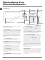
Instructions for the fitter
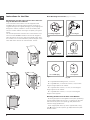
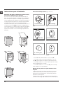
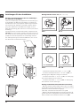
Mounting the wooden panel onto the door and inser-
ting the machine into cabinets:
In the case where the machine must be shipped for final
installation after the wooden panel has been mounted, we
suggest leaving it in its original packaging. The packaging was
designed to make it possible to mount the wooden panel
onto the machine without removing it completely (see figures
below).
The wooden panel that covers the face of the machine must
not be less than 18 mm in thickness and can be hinged on
either the right or left. For the sake of practicality when using
the machine, we recommend that the panel be hinged on the
same side as the door for the machine itself - the left.
A
B
C
D
E
Tur seite
Door Mounting Accessories (Fig. 1-2-3-4-5).
Fig. 1
N° 2 Hinges
N° 1 Magnet N° 1 Magnet plate
N° 1 Rubber plug
N° 2 Hinge Supports
N° 4 Spacers
Fig. 2
Fig. 3 Fig. 4
Fig. 5
Fig. 4/B
- No. 6 type A self-threading screws, l =13 mm.
- No. 2 type B metric, countersunk screws, l =25; for faste-
ning the magnet plate to the cabinet.
- No. 4 type C metric screws, l =15 mm; for mounting the
hinge supports to the cabinet.
- No. 4 type D metric screws, l =7 mm; for mounting the
hinges on the supports.
Mounting the Parts onto the Face of the Machine.
- Fit the hinge supports to the appliance front panel, positioning
the hole marked with an arrow in fig. 1 so that it is on the inner
side of the front panel. Fit a spacer (fig. 4/B) between the
surfaces using type C screws.
- Fit the magnet plate at the top of the opposite side, using
type B screws to fix two spacers (fig. 4/B) between the plate
and the surface.

GB
5
Using the Drilling Template.
- To trace the positions of the holes on the left-hand side of
the panel, align the drilling template to the top left side of the
panel using the lines traced on the extremities as a reference.
- To trace the positions of the holes on the right-hand side of
the panel, align the drilling template to the top right side of the
panel.
- Use an appropriately sized router to mill the holes for the two
hinges, the rubber plug and the magnet.
Mounding the Parts onto the Wooden Panel (Door).
- Insert the hinges into the holes (the movable part of the hin-
ge must be positioned facing away from the panel) and fasten
them with the 4 type A screws.
- Insert the magnet into the top hole on the opposite side of
the hinges and fasten it with the two type B screws.
- Insert the rubber plug into the bottom hole.
The panel is now ready to be mounted onto the machine.
Mounting the Panel into the machine.
Insert the nib of the hinge (indicated by the arrow in fig. 2) into
the hole for the hinge and push the panel towards the front of
the machine. Fasten the two hinges with the type D screws.
Fastening the plinth guide.
If the machine is installed at the end of a set of modular
cabinets, mount either one or both of the guides for the base
molding (as shown in fig. 8). Adjust them for depth based on
the position of the base molding, and, if necessary, fasten the
base to the guides (fig. 9).
This is how to assemble the plinth guide (fig. 8):
Fasten angle P using screw R, insert plinth guide Q into the
special slot and once it is in the desired position, lock it in
place using angle P and screw R.
Inserting the machine into the Cabinet.
- Push the machine into the opening, aligning it with the cabi-
nets (fig. 6).
- Regulate the adjustable feet to raise the machine to the
appropriate height.
- To adjust the position of the wooden panel in both the
vertical and horizontal directions, use the C and D screws, as
shown in fig. 7.
Important: close the lower part of the appliance front by
ensuring that the plinth rests against the floor.
Fig. 8 Fig. 9
Accessories provided for the height adjustment.
The following can be found inside the polystyrene lid (fig. 10): 2
crossbars (G), 1 strip (M)
the following can be found inside
the appliance drum:
4 additional feet (H),
4 screws (I),
4 screws (R),
4 nuts (L),
2 plinth guides (Q)
Adjusting the appliance height.
The height of the appliance can be adjusted (from 815 mm to
835 mm), by turning the 4 feet.
Should you require the appliance to be placed higher than the
above height, you need to use the following accessories to
raise it to up to 870 mm:
the two crossbars (G); the 4 feet (H); the 4 screws (I); the 4
nuts (L) then perform the following operations (fig. 11):
remove the 4 original feet, place a crossbar G at the front of the
appliance, fastening it in place using screws I (screwing them in
where the original feet were) then insert the new feet H.
Repeat the same operation at the back of the appliance.
Now adjust feet H to raise or lower the appliance from 835 mm
to 870 mm.
Once you have reached the desired height, lock nuts L onto
crossbar G.
To adjust the appliance to a height between 870 mm and 900
mm, you need to mount strip M, adjusting feet H to the requi-
red height.
Insert the strip as follows:
loosen the three screws N situated at the front of the Top cover
of the appliance, insert strip M as shown in fig. 12, then fasten
screws N.
D
C
C
570
min
815
540
595
820 ÷ 900
600 min
Fig. 6 Fig. 7
L
I
H
G
M
Fig. 11 Fig. 12
Fig. 10

6
GB
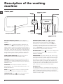
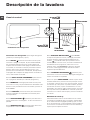
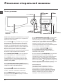
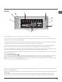
Detergent dispenser drawer: used to dispense
detergents and washing additives (see “Detergents and
laundry”).
ON/OFF button : press this briefly to switch the ma-
chine on or off. The START/PAUSE indicator light, which
flashes slowly in a green colour shows that the machine is
switched on. To switch off the washing machine during the
wash cycle, press and hold the button for approximately 2
seconds; if the button is pressed briefly or accidentally the
machine will not switch off. If the machine is switched off
during a wash cycle, this wash cycle will be cancelled.
WASH CYCLE SELECTOR buttons: used to set the
desired wash cycle (see “Table of wash cycles”).
MEMORY button: press and hold the button to store a
cycle with your own set of preferences in the memory of
the machine. To recall a previously stored cycle, press the
MEMORY button.
FUNCTION buttons: press the button to select the
desired function. The corresponding indicator light on the
display will switch on.
SPIN button : press to reduce or completely exclude
the spin cycle - the value is indicated on the display.
TEMPERATURE button : press to decrease the tem-
perature: the value will be shown on the display.
CONTROL PANEL LOCK button : to activate
the control panel lock, press and hold the button for
approximately 2 seconds. When the symbol is
illuminated, the control panel is locked. This means it
is possible to prevent wash cycles from being modified
accidentally, especially where there are children in the
home. To deactivate the control panel lock, press and
hold the button for approximately 2 seconds.
DELAYED START button : press to set a delayed start
time for the selected wash cycle. The delay time will be
shown on the display.
START/PAUSE button with indicator light: when the gre-
en indicator light flashes slowly, press the button to start a
wash cycle. Once the cycle has begun the indicator light
will remain lit in a fixed manner. To pause the wash cycle,
press the button again; the indicator light will flash in an
orange colour. If the symbol is not illuminated, the door
may be opened. To start the wash cycle from the point at
which it was interrupted, press the button again.
Standby mode
This washing machine, in compliance with new energy sa-
ving regulations, is fitted with an automatic standby system
which is enabled after about 30 minutes if no activity is
detected. Press the ON-OFF button briefly and wait for the
machine to start up again.
Description of the washing
machine
SPIN SPEED
Button
START/PAUSE
button with indicator
light
Control panel
TEMPERATURE
Button
WASH
CYCLE
SELECTOR
Buttons
Detergent dispenser drawer
FUNCTION
buttons
ON/OFF
button
DISPLAY
DELAYED
START
Button
MEMORY
Button
CONTROL PANEL
LOCK button

GB
7
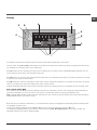
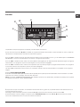
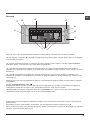
Display
The display is useful when programming the machine and provides a great deal of information.
The two upper strings A and B provide details of the wash cycle selected, the wash cycle phase in progress and all informa-
tion relating to the progress status of the wash cycle.
String C shows the time remaining until the end of the wash cycle in progress and, if a DELAYED START has been set, the
time remaining until the start of the selected wash cycle.
String D shows the maximum spin speed value (this depends on the selected wash cycle); if the wash cycle does not include
a spin cycle, the string remains unused.
String E shows the maximum temperature value which may be selected (this depends on the wash cycle used); if the tempe-
rature of the wash cycle cannot be modified, the string remains unused.
Indicator lights F correspond to the functions and light up when the selected function is compatible with the set wash cycle.
Door locked symbol
If the symbol is lit, this indicates that the washing machine door is blocked to prevent it from being opened accidentally. To
prevent any damage from occurring, wait for the symbol to switch itself off before opening the appliance door.
N.B.: if the DELAYED START function has been activated, the door cannot be opened; pauses the machine by pressing the
START/PAUSE button if you wish to open it.
! The first time the machine is switched on, you will be asked to select the language and the display will automatically show
the language selection menu.
To select the desired language press the X and Y buttons; to confirm the selection press the Z button.
To change the language switch off the machine and press buttons X, Y, Z simultaneously until an alarm is heard: the
language-selection menu will be displayed again.
A
B
C
D
E
Z
X
Y
START/PAUSE
button with indicator
light
F

8
GB
Running a wash cycle
1. SWITCH THE MACHINE ON. Press the button;
the text HELLO will appear on the display and the
START/PAUSE indicator light will flash slowly in a green
colour.
2. LOAD THE LAUNDRY. Open the porthole door.
Load the laundry, making sure you do not exceed
the maximum load value indicated in the table of
programmes on the following page.
3. MEASURE OUT THE DETERGENT. Pull out the
detergent dispenser drawer and pour the detergent into
the relevant compartments as described in “Detergents
and laundry”.
4. CLOSE THE DOOR.
5. SELECT THE WASH CYCLE. Press one of the WASH
CYCLE SELECTOR buttons to select the required wash
cycle; the name of the wash cycle will appear on the
display. A temperature and spin speed is set for each
wash cycle; these may be adjusted. The duration of the
cycle will appear on the display.
6. CUSTOMISE THE WASH CYCLE. Use the relevant
buttons:
Modifying the temperature and/or spin
speed. The machine automatically selects the
maximum temperature and spin speed set for the
selected wash cycle; these values cannot therefore
be increased. The temperature can be decreased by
pressing the button, until the cold wash “OFF”
setting is reached. The spin speed may be progressively
reduced by pressing the button, until it is completely
excluded (the “OFF” setting). If these buttons are
pressed again, the maximum values are restored.
! Exception: if the (60°C)
(1st press of the button)
programme is selected, the temperature can be
increased up to a value of 90°C.
Setting a delayed start.
To set a delayed start for the selected programme,
press the corresponding button repeatedly until the
required delay period has been reached. When this
option is enabled, the symbol lights up on the
display. To remove the delayed start function press the
button until the text “OFF” appears on the display.
Modifying the cycle settings.
• Press the button to enable the function; the indicator
light corresponding to the button will switch on.
• Press the button again to disable the function; the
indicator light will switch off.
! If the selected function is not compatible with the
programmed wash cycle, the indicator light will flash
and the function will not be activated.
! If the selected function is not compatible with
another function which has been selected previously,
the indicator light corresponding to the first function
selected will flash and only the second function will
be activated; the indicator light corresponding to the
enabled function will remain lit.
! The functions may affect the recommended load value
and/or the duration of the cycle.
7. START THE PROGRAMME. Press the START/
PAUSE button. The corresponding indicator light will
become green, remaining lit in a fixed manner, and the
door will be locked (the DOOR LOCKED symbol will
be on). During the wash cycle, the name of the phase
in progress will appear on the display. To change a
wash cycle while it is in progress, pause the washing
machine using the START/PAUSE button (the START/
PAUSE indicator light will flash slowly in an orange
colour); then select the desired cycle and press the
START/PAUSE button again.
To open the door while a cycle is in progress, press
the START/PAUSE button; if the DOOR LOCKED
symbol is switched off the door may be opened. Press
the START/PAUSE button again to restart the wash
cycle from the point at which it was interrupted.
8. THE END OF THE WASH CYCLE. This will be
indicated by the text “END OF CYCLE” on the display;
when the DOOR LOCKED symbol switches off
the door may be opened. Open the door, unload the
laundry and switch off the machine.
! If you wish to cancel a cycle which has already begun,
press and hold the button. The cycle will be stopped
and the machine will switch off.

GB
9
Wash cycles and functions
Wash functions
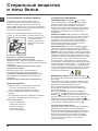
Super Wash
This option offers a high-
performance wash due to the
greater quantity of water used
in the initial phase of the cycle,
and due to the increased wash
cycle duration, is particular-
ly useful for the removal of
stubborn stains. It can be used
with or without bleach. If you
desire bleaching, insert the
extra tray compartment (4) into
compartment 1. When pouring
in the bleach, be careful not
to exceed the “max” level marked on the central pivot (see
figure). To bleach laundry without carrying out a full wash
cycle, pour the bleach into the extra compartment 4, select
the “Rinse” cycle and activate the “Super Wash” option.
! The use of extra compartment 4 excludes the “Pre-wash”
function.
! It cannot be used with the , , , , “Fast Spin Cottons”,
“Pump out”.
Extra Rinse
By selecting this option, the efficiency of the rinse is increased
and optimal detergent removal is guaranteed. It is particularly
useful for sensitive skin.
! It cannot be used with the “Fastwash 30’”, , , “Fast Spin
Cottons”, “Pump out”.
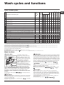
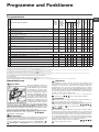
Table of wash cycles
Easy Iron
By selecting this function, the wash and spin cycles will be modified
in order to reduce the formation of creases. At the end of the cycle
the washing machine will perform slow rotations of the drum; the
EASY IRON and START/PAUSE indicator lights will flash (orange)
and the text “END OF CYCLE” will appear on the display. To end
the cycle, press the START/PAUSE button or the EASY IRON
button. To drain the water so that the laundry may be removed,
press the START/PAUSE button or the EASY IRON button.
! It cannot be used with the , “Fastwash 30’”, , , .
Prewash
If this function is selected, the pre-wash cycle will run; this is
useful for removing stubborn stains.
N.B.: put the detergent in the relevant compartment.
! It cannot be used with the , , , , ,
(60°), (40°),
.
Eco Wash
The Eco Wash function saves energy by not heating the
water used to wash your laundry – an advantage both to the
environment and to your energy bill. Instead, intensified wash
action and water optimisation ensure great wash results in the
same average time of a standard cycle.
For the best washing results we recommend the usage of a
liquid detergent.
! It cannot be used with the , , , , , .
M
AX
1
2
4
3
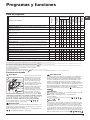
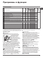
Wash cycles
Description of the wash cycle
Max. temp.
(°C)
Max. speed
(rpm)
Detergents
Max. load
(kg)
Residual dam-
pness %
Energy con-
sumption kWh
Total water lt
Cycle duration
Prewash
Wash
Fabric
softener
Bleach
Anti Stain
40° 1400
4 - -
-
180’
Standard Cotton 60° (1) (1st press of the button): heavily soiled whites and
delicate colours.
60°
(Max. 90°)
1400
(3)
7 53 1,10 52,5 190’
Standard Cotton 40° (2) (2nd press of the button): lightly soiled whites and
delicate colours.
40° 1400 -
7 53 0,99
82
185’
Standard Cotton 20° (3rd press of the button): lightly soiled whites and
delicate colours.
20° 1400 -
7 - -
-
170’
Synthetics Resistant (1st press of the button): heavily soiled resistant colours. 60° 800
3 44 0,93 47 110’
Synthetics Resistant (4) (1st press of the button): lightly soiled resistant colours. 40° 800
3 44 0,57 46 95’
Synthetics Delicate (2nd press of the button): lightly soiled resistant colours. 40° 800
3 - - - 70’
Fastwash 60' (1st press of the button): to refresh normal soiled garments quic-
kly (not suitable for wool, silk and clothes which require washing by hand).
60° 1400 -
- 3,5 53 0,81 40 60’
Fastwash 30' (2nd press of the button): to refresh lightly soiled garments quic-
kly (not suitable for wool, silk and clothes which require washing by hand).
30° 800 -
- 3 71 0,15 35 30’
M
My Cycle: allows for any wash cycle to be stored.
Anti Allergy
60° 1400 -
- 4 - - - 195’
Woolmark Platinum (Wool): for wool, cashmere, etc. 40° 800 -
- 1,5 - - - 70’
Delicates
30° 0 -
- 1 - - - 80’
Fast Spin Cottons (1st press of the button) - 1400 - - - - 7 - - - 16’
Rinse Cottons (2nd press of the button) - 1400 - -
7 - - - 36’
Pump out (3rd press of the button) - 0 - - - - 7 - - - 2’
The length of cycle shown on the display or in this booklet is an estimation only and is calculated assuming standard working conditions. The actual duration can vary according to factors
such as water temperature and pressure, the amount of detergent used, the amount and type of load inserted, load balancing and any wash options selected.
1) Test wash cycle in compliance with directive 1061/2010: set wash cycle 60°C (1st press of the button).
This cycle is designed for cotton loads with a normal soil level and is the most efficient in terms of both electricity and water consumption; it should be used for garments which can be
washed at 60°C. The actual washing temperature may differ from the indicated value.
2) Test wash cycle in compliance with directive 1061/2010: set wash cycle 40°C (2nd press of the button).
This cycle is designed for cotton loads with a normal soil level and is the most efficient in terms of both electricity and water consumption; it should be used for garments which can be
washed at 40°C. The actual washing temperature may differ from the indicated value.
3) At 60 °C the “Prewash” function cannot be selected.
For all Test Institutes:
2) Long wash cycle for cottons: set wash cycle 40°C (2nd press of the button).
4) Long wash cycle for synthetics: set wash cycle 60°C (1st press of the button); temperature of 40°C (press TEMPERATURE button).

10
GB
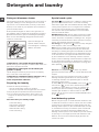
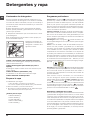
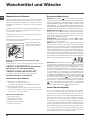
Detergent dispenser drawer
Good washing results also depend on the correct dose of
detergent: adding too much detergent will not necessa-
rily result in a more efficient wash, and may in fact cause
build up on the inside of your appliance and contribute to
environmental pollution.
! Use powder detergent for white cotton garments, for
pre-washing, and for washing at temperatures over 60°C.
! Follow the instructions given on the detergent packaging.
! Do not use hand washing detergents because these
create too much foam.
Open the detergent di-
spenser drawer and pour
in the detergent or washing
additive, as follows.
compartment 1: Pre-wash detergent (powder)
Before pouring in the detergent, make sure that extra com-
partment 4 has been removed.
compartment 2: Detergent for the wash cycle
(powder or liquid)
Liquid detergent should only be poured in immediately
prior to the start of the wash cycle.
compartment 3: Additives (fabric softeners, etc.)
The fabric softener should not overflow the grid.
extra compartment 4: Bleach
Preparing the laundry
• Divide the laundry according to:
- the type of fabric/the symbol on the label
- the colours: separate coloured garments from whites
• Empty all garment pockets and check the buttons.
• Do not exceed the listed values, which refer to the
weight of the laundry when dry: see “Table of wash
cycles”.
How much does your laundry weigh?
1 sheet 400-500 g
1 pillow case 150-200 g
1 tablecloth 400-500 g
1 bathrobe 900-1200 g
1 towel 150-250 g
Special wash cycles
Anti Stain : this programme is suitable to heavily-soiled
garments with resistant colours. It ensures a washing
class that is higher than the standard class (A class). When
running the programme, do not mix garments of different
colours. We recommend the use of powder detergent.
Pre-treatment with special additives is recommended if
there are obstinate stains.
Standard Cotton 20°: ideal for lightly soiled cotton loads.
The effective performance levels achieved at cold tempe-
ratures, which are comparable to washing at 40°, are gua-
ranteed by a mechanical action which operates at varying
speed, with repeated and frequent peaks.
Anti Allergy: use programme to remove major allergens
such as pollen, mites, cat’s and dog’s hair.
Wool: the wool wash cycle on this Hotpoint/Ariston ma-
chine has been tested and approved by The Woolmark
Company for washing wool garments labelled as hand wa-
shable provided that the garments are washed according
to the instructions on the garment label and those issued
by the manufacturer of this washing machine. Hotpoint/
Ariston is the first washing machine brand to be approved
by The Woolmark Company for Apparel Care- Platinum for
its washing performance and consumption of energy and
water. (M1126)
Delicates: use programme to wash very delicate
garments with decorative features, such as diamantes and
sequins.
We recommend turning the garments inside out before
washing and placing small items into the special bag
for washing delicates. Use liquid detergent on delicate
garments for best results.
To wash Silk garments and Curtains, select cycle and
then function (in this case it will also be possible
to enable the “Extra Rinse” function); the machine will
end the cycle while the laundry is soaking and the
indicator light will flash. To drain the water so that the
laundry may be removed, press the START/PAUSE button
or the button.
Load balancing system
Before every spin cycle, to avoid excessive vibrations and
to distribute the load in a uniform manner, the drum rotates
continuously at a speed which is slightly greater than the
washing rotation speed. If, after several attempts, the load
is not balanced correctly, the machine spins at a reduced
spin speed. If the load is excessively unbalanced, the
washing machine performs the distribution process instead
of spinning. To encourage improved load distribution and
balance, we recommend small and large garments are
mixed in the load.
Detergents and laundry
M
AX
1
2
4
3

GB
11
Precautions and tips
! This washing machine was designed and constructed in
accordance with international safety regulations. The fol-
lowing information is provided for safety reasons and must
therefore be read carefully.
General safety
• This appliance was designed for domestic use only.
• This appliance is not intended for use by persons (inclu-
ding children) with reduced physical, sensory or mental
capabilities, or lack of experience and knowledge, unless
they have been given supervision or instruction concer-
ning use of the appliance by a person responsible for
their safety. Children should be supervised to ensure that
they do not play with the appliance.
• Do not touch the machine when barefoot or with wet or
damp hands or feet.
• Do not pull on the power supply cable when unplugging
the appliance from the electricity socket. Hold the plug
and pull.
• Do not open the detergent dispenser drawer while the
machine is in operation.
• Do not touch the drained water as it may reach extreme-
ly high temperatures.
• Never force the porthole door. This could damage the safety
lock mechanism designed to prevent accidental opening.
• If the appliance breaks down, do not under any circum-
stances access the internal mechanisms in an attempt
to repair it yourself.
• Always keep children well away from the appliance while
it is operating.
• The door can become quite hot during the wash cycle.
• If the appliance has to be moved, work in a group of two
or three people and handle it with the utmost care. Never
try to do this alone, because the appliance is very heavy.
• Before loading laundry into the washing machine, make
sure the drum is empty.
Disposal
• Disposing of the packaging materials: observe local regu-
lations so that the packaging may be re-used.
• The European Directive 2012/19/EU on Waste Electrical
and Electronic Equipment, requires that old household
electrical appliances must not be disposed of in the normal
unsorted municipal waste stream. Old appliances must be
collected separately in order to optimise the recovery and
recycling of the materials they contain and reduce the im-
pact on human health and the environment. The crossed
out “wheeled bin” symbol on the product reminds you of
your obligation, that when you dispose of the appliance it
must be separately collected. Consumers should contact
their local authority or retailer for information concerning the
correct disposal of their old appliance.
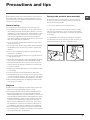
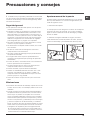
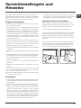
Opening the porthole door manually
In the event that it is not possible to open the porthole
door due to a powercut, and if you wish to remove the
laundry, proceed as follows:
1. remove the plug from the electrical socket.
2. make sure the water level inside the machine is lower
than the door opening; if it is not, remove excess water
using the drain hose, collecting it in a bucket as indicated
in the figure.
3. pull outwards using the tab as indicated in the figure,
until the plastic tie-rod is freed from its stop position; pull
downwards and open the door at the same time.

12
GB
Care and maintenance
Cutting off the water and electricity
supplies
• Turn off the water tap after every wash cycle. This will limit
wear on the hydraulic system inside the washing machine
and help to prevent leaks.
• Unplug the washing machine when cleaning it and du-
ring all maintenance work.
Cleaning the washing machine
The outer parts and rubber components of the appliance
can be cleaned using a soft cloth soaked in lukewarm
soapy water. Do not use solvents or abrasives.
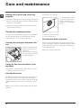
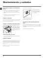
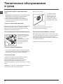
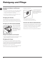
Cleaning the detergent dispenser dra-
wer
Remove the dispenser by
raising it and pulling it out
(see figure).
Wash it under running wa-
ter; this operation should be
repeated frequently.
Caring for the door and drum of your
appliance
• Always leave the porthole door ajar in order to prevent
unpleasant odours from forming.
Cleaning the pump
The washing machine is fitted with a self-cleaning pump
which does not require any maintenance. Sometimes,
small items (such as coins or buttons) may fall into the pre-
chamber which protects the pump, situated in its bottom
part.
! Make sure the wash cycle has finished and unplug the
appliance.
To access the pre-chamber:
1. unscrew the lid by rota-
ting it anti-clockwise (see
figure): a little water may
trickle out. This is perfectly
normal;
2. clean the inside thoroughly;
3. screw the lid back on;
Checking the water inlet hose
Check the inlet hose at least once a year. If there are any
cracks, it should be replaced immediately: during the wash
cycles, water pressure is very strong and a cracked hose
could easily split open.
! Never use second-hand hoses.
1
2

GB
13
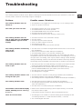
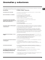
Troubleshooting
Your washing machine could fail to work. Before contacting the Technical Assistance Centre (see “Assistance”), make sure
that the problem cannot be solved easily using the following list.
Problem:
The washing machine does not
switch on.
The wash cycle does not start.
The washing machine does not
take in water (the text “NO WATER,
CHECK SUPPLY” appears on the
display).
The washing machine continuously
takes in and
drains water.
The washing machine does not
drain or spin.
The washing machine vibrates a lot
during the spin cycle.
The washing machine leaks.
The machine is locked and the display
flashes, indicating an error code (e.g.
F-01, F-..).
There is too much foam.
Possible causes / Solutions:
• The appliance is not plugged into the socket fully, or is not making contact.
• There is no power in the house.
• The washing machine door is not closed properly.
• The ON/OFF button has not been pressed.
• The START/PAUSE button has not been pressed.
• The water tap has not been opened.
• A delayed start has been set (see “Running a wash cycle”).
• The water inlet hose is not connected to the tap.
• The hose is bent.
• The water tap has not been opened.
• There is no water supply in the house.
• The pressure is too low.
• The START/PAUSE button has not been pressed.
• The drain hose is not fitted at a height between 65 and 100 cm from the floor
(see “Installation”).
• The free end of the hose is under water (see “Installation”).
• The wall drainage system is not fitted with a breather pipe.
If the problem persists even after these checks, turn off the water tap, switch
the appliance off and contact the Assistance Service. If the dwelling is on one of
the upper floors of a building, there may be problems relating to water drainage,
causing the washing machine to fill with water and drain continuously. Special
anti-draining valves are available in shops and help to avoid this inconvenience.
• The wash cycle does not include draining: some wash cycles require the drain
phase to be started manually (see “Wash cycles and functions”).
• The EASY IRON function has been activated: To complete the wash cycle,
press the START/PAUSE button (see “Wash cycles and functions”).
• The drain hose is bent (see “Installation”).
• The drainage duct is clogged.
• The drum was not unlocked correctly during installation (see “Installation”).
• The washing machine is not level (see “Installation”).
• The washing machine is trapped between cabinets and walls (see “Installation”).
• The water inlet hose is not screwed on properly (see “Installation”).
• The detergent dispenser drawer is blocked (for cleaning instructions, see
“Care and maintenance”).
• The drain hose is not fixed properly (see “Installation”).
• Switch off the machine and unplug it, wait for approximately 1 minute and
then switch it back on again.
If the problem persists, contact the Technical Assistance Service.
• The detergent is not suitable for machine washing (it should display the text
“for washing machines” or “hand and machine wash”, or the like).
• Too much detergent was used.

14
GB
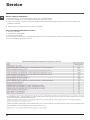
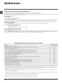
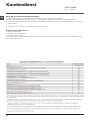
Service
Before calling for Assistance:
• Check whether you can solve the problem alone (see “Troubleshooting”);
• Restart the programme to check whether the problem has been solved;
• If this is not the case, contact an authorised Technical Assistance Centre using the telephone number provided on the
guarantee certificate.
! Always request the assistance of authorised technicians.
Have the following information to hand:
• the type of problem;
• the appliance model (Mod.);
• the serial number (S/N).
This information can be found on the data plate applied to the rear of the washing machine, and can also be found on the
front of the appliance by opening the door.

15
I
Italiano
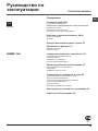
Sommario
Installazione, 16-17-18-19
Disimballo e livellamento
Collegamenti idraulici ed elettrici
Primo ciclo di lavaggio
Dati tecnici
Istruzioni per l’installatore
Descrizione della lavabiancheria, 20-21
Pannello di controllo
Display
Come effettuare un ciclo di lavaggio, 22
Programmi e funzioni, 23
Tabella dei programmi
Funzioni di lavaggio
Detersivi e biancheria, 24
Cassetto dei detersivi
Preparare la biancheria
Programmi particolari
Sistema bilanciamento del carico
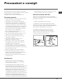
Precauzioni e consigli, 25
Sicurezza generale
Smaltimento
Apertura manuale della porta oblò
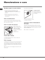
Manutenzione e cura, 26
Escludere acqua e corrente elettrica
Pulire la lavabiancheria
Pulire il cassetto dei detersivi
Curare oblò e cestello
Pulire la pompa
Controllare il tubo di alimentazione dell’acqua
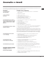
Anomalie e rimedi, 27
Assistenza, 28
Assistenza Attiva 7 giorni su 7
I
LAVABIANCHERIA
BWMD 742
Istruzioni per l’uso

16
I
! È importante conservare questo libretto per poterlo con-
sultare in ogni momento. In caso di vendita, di cessione o
di trasloco, assicurarsi che resti insieme alla lavabiancheria
per informare il nuovo proprietario sul funzionamento e sui
relativi avvertimenti.
! Leggere attentamente le istruzioni: ci sono importanti
informazioni sull’installazione, sull’uso e sulla sicurezza.
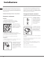
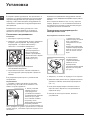
Disimballo e livellamento
Disimballo
1. Disimballare la lavabiancheria.
2. Controllare che la lavabiancheria non abbia
subìto danni nel trasporto. Se fosse danneggiata
non collegarla e contattare il rivenditore.
3. Rimuovere le 4 viti di
protezione per il trasporto
e il gommino con il relativo
distanziale, posti nella parte
posteriore (vedi figura).
4. Chiudere i fori con i tappi di plastica in dotazione.
5. Conservare tutti i pezzi: qualora la lavabiancheria debba
essere trasportata, dovranno essere rimontati.
! Gli imballaggi non sono giocattoli per bambini.
Livellamento
1. Installare la lavabiancheria su un pavimento piano e rigi-
do, senza appoggiarla a muri, mobili o altro.
2. Se il pavimento non fosse
perfettamente orizzontale,
compensare le irregolarità
svitando o avvitando i piedini
anteriori (vedi figura); l’ango-
lo di inclinazione, misurato
sul piano di lavoro, non deve
superare i 2°.
Un accurato livellamento dà stabilità alla macchina ed
evita vibrazioni, rumori e spostamenti durante il funzio-
namento. In caso di moquette o di un tappeto, regolare i
piedini in modo da conservare sotto la lavabiancheria uno
spazio sufficiente per la ventilazione.
Collegamenti idraulici ed elettrici
Collegamento del tubo di alimentazione dell’acqua
1. Collegare il tubo di
alimentazione avvitandolo
a un rubinetto d’acqua
fredda con bocca filettata
da 3/4 gas (vedi figura).
Prima di allacciare, far
scorrere l’acqua finché
non sia limpida.
2. Collegare il tubo di ali-
mentazione alla lavabian-
cheria avvitandolo all’ap-
posita presa d’acqua,
nella parte posteriore in
alto a destra (vedi figura).
3. Fare attenzione che nel tubo non ci siano né pieghe né
strozzature.
! La pressione idrica del rubinetto deve essere compresa
nei valori della tabella Dati tecnici
(vedi pagina a fianco).
! Se la lunghezza del tubo di alimentazione non fosse
sufficiente, rivolgersi a un negozio specializzato o a un
tecnico autorizzato.
! Non utilizzare mai tubi già usati.
! Utilizzare quelli in dotazione alla macchina.
Installazione

17
I
Collegamento del tubo di scarico
Collegare il tubo di scari-
co, senza piegarlo, a una
conduttura di scarico o a
uno scarico a muro posti
tra 65 e 100 cm da terra;
oppure appoggiarlo al
bordo di un lavandino o
di una vasca, legando la
guida in dotazione al
rubinetto (vedi figura).
L’estremità libera del tubo
di scarico non deve rima-
nere immersa nell’acqua.
! È sconsigliato usare tubi di prolunga; se indispensabile,
la prolunga deve avere lo stesso diametro del tubo origi-
nale e non superare i 150 cm.
Collegamento elettrico
Prima di inserire la spina nella presa della corrente, accer-
tarsi che:
• la presa abbia la messa a terra e sia a norma
di legge;
• la presa sia in grado di sopportare il carico
massimo di potenza della macchina, indicato nella
tabella Dati tecnici (vedi a fianco);
• la tensione di alimentazione sia compresa nei
valori indicati nella tabella Dati tecnici (vedi a
fianco);
• la presa sia compatibile con la spina della
lavabiancheria. In caso contrario sostituire la
presa o la spina.
! La lavabiancheria non va installata all’aperto, nemmeno
se lo spazio è riparato, perché è molto pericoloso lasciar-
la esposta a pioggia e temporali.
! A lavabiancheria installata, la presa della corrente deve
essere facilmente raggiungibile.
! Non usare prolunghe e multiple.
! Il cavo non deve subire piegature o compressioni.
! Il cavo di alimentazione deve essere sostituito solo da
tecnici autorizzati.
Attenzione! L’azienda declina ogni responsabilità qualora
queste norme non vengano rispettate.
Primo ciclo di lavaggio
Dopo l’installazione, prima dell’uso, effettuare un ciclo di
lavaggio con detersivo e senza biancheria impostando il
programma
(60° C).
65 - 100 cm
Dati tecnici
Modello
BWMD 742
Dimensioni
larghezza cm 59,5
altezza cm 81,5
profondità cm 54,5
Capacità
da 1 a 7 kg
Collegamenti
elettrici
Vedi targhetta caratteristiche tecniche
applicata sulla macchina
Collegamenti
idrici
pressione massima 1 MPa (10 bar)
pressione minima 0,05 MPa (0,5 bar)
capacità del cesto 52 litri
Velocità di cen-
trifuga
sino a 1400 giri al minuto
Programmi di
prova
secondo la
direttive
1061/2010 e
1015/2010
programma
(60°) (1° pressione del tasto);
Cotone standard 60°C.
programma
(40°) (2° pressione del tasto);
Cotone standard 40°C.
Questa apparecchiatura è conforme alle
seguenti Direttive Comunitarie:
- 2004/108/CE (Compatibilità
Elettromagnetica)
- 2006/95/CE (Bassa Tensione)
- 2012/19/EU

18
I
Istruzioni per l’installatore
Applicazione del pannello in legno alla porta e inse-
rimento della macchina nei mobili:
Nel caso in cui, dopo il montaggio del pannello in legno, sia
necessario spedire la macchina per l’installazione finale,
consigliamo di lasciarla nel suo imballo originale. A questo
scopo l’imballo è stato realizzato in modo da permettere il
montaggio del pannello di legno sulla macchina senza disim-
ballare completamente il prodotto (vedi figure sottostanti).
Il pannello di legno che copre la facciata non deve essere di
spessore inferiore a 18 mm e può essere incernierato sia sul
lato destro che sinistro. Per ragioni di praticità d’uso della
macchina consigliamo lo stesso senso di apertura dell’oblò
con le cerniere applicate sul lato sinistro.
A
B
C
D
E
Tur seite
Accessori montaggio portina (Fig. 1-2-3-4-5).
Fig. 1
N° 2 cerniere
N° 1 Magnete N° 1 Riscontro magnete
N° 1 Tassello in gomma
N° 2 Supporti cerniera
N° 4 Distanziali
Fig. 2
Fig. 3 Fig. 4
Fig. 5
Fig. 4/B
- n° 6 viti autofilettanti l = 13 mm “tipo A”.
- n° 2 viti metriche testa svasata l = 25 mm “tipo B”; per il
fissaggio del riscontro magnete al mobile.
- n° 4 viti metriche l = 15 mm “tipo C”; per il montaggio dei
supporti cerniera al mobile.
- n° 4 viti metriche l = 7 mm “tipo D”; per il montaggio delle
cerniere ai supporti.
Montaggio dei particolari sulla facciata della macchina.
- Montare i supporti cerniera alla facciata posizionando il
foro indicato da una freccia nella fig. 1 verso l’interno della
facciata interponendo un distanziale (fig. 4/B), utilizzando le
viti tipo C.
- Montare il riscontro magnete dalla parte opposta in alto
interponendo due distanziali (fig. 4/B) utilizzando le due viti
tipo B.

19
I
Uso della maschera di foratura.
- Per tracciare le posizioni dei fori sul lato sinistro del pan-
nello, allinerare la maschera di foratura al lato superiore e
sinistro del pannello facendo riferimento alle linee tracciate
alle estremità.
- Per tracciare le posizioni dei fori sul lato destro del pannel-
lo, allinerare la maschera di foratura al lato superiore e destro
del pannello.
- Con una fresa di adeguate dimensioni realizzare le quattro
sedi che dovranno alloggiare le due cerniere, il tassello di
gomma e il magnete.
Montaggio dei particolari sul pannello di legno (Antina).
- Inserire le cerniere nelle sedi predisposte (la parte mobile
della cerniera deve trovarsi verso l’esterno del pannello) e
fissarle con 4 viti del tipo A.
- Inserire il magnete nella sede in alto dalla parte opposta
alle cerniere e fissarlo con due viti tipo B.
- Inserire il tassello in gomma nella sede in basso.
Il pannello è ora pronto per essere montato sulla macchina.
Montaggio del pannello alla macchina.
Inserire il nasello della cerniera indicato dalla freccia nella fig.
2 nella sede del supporto cerniera spingere il pannello verso
la facciata della macchina e fissare le due cerniere con le
due viti tipo D.
Fissaggio della guida zoccolo.
Se la macchina è installata ad una estremità della cucina
componibile montare una o entrambe le guide zoccolo
come indicato in fig. 8, regolandone la profondità in funzione
della posizione dello zoccolo e se necessario fissarlo alle
stesse (fig. 9).
Per montare la guida zoccolo agire cone segue (fig. 8):
Fissare la squadretta P con la vite R, infilare la guida zoccolo
Q nell’apposita asola e una volta posizionata nel punto desi-
derato bloccarla alla squadretta P con la vite R.
Inserimento della macchina nei mobili.
- Spingere l’apparecchio nell’apertura allineandola con gli
altri mobili (fig. 6).
- Agire sui piedini di regolazione per portare la macchina
all’altezza desiderata.
- Per regolare la posizione del pannello in legno in senso
verticale ed orizzontale, agire sulle viti C e D come indicato
in fig. 7.
Importante: chiudere la parte inferiore della facciata con lo
zoccolo a battuta sul pavimento.
Fig. 8 Fig. 9
Accessori in dotazione per la regolazione in altezza.
Alloggiate nel coperchio di polistirolo (fig. 10) si trovano:
2 traverse (G); 1 listello (M)
all’interno del cestello si trovano:
4 piedini supplementari (H)
4 viti (I)
4 viti (R)
4 dadi (L)
2 guide zoccolo (Q)
Regolazione in altezza della macchina.
La macchina può essere regolata in altezza (da 815 mm a 835
mm) agendo sui 4 piedini.
Se si desidera portarla ad un’altezza superiore a quella soprain-
dicata, arrivando fino a 870 mm, occorre utilizzare i seguenti
accessori:
le 2 traverse (G); i 4 piedini (H); le 4 viti (I); i 4 dadi (L), quindi
agire come segue (fig. 11):
togliere i 4 piedini originali, posizionare una traversa G nella par-
te anteriore della macchina, fissarla con le viti I (avvitandole nei
fori dove erano montati i piedini originali) quindi inserire i nuovi
pedini H.
Ripetere la stessa operazione nella parte posteriore della macchina.
A questo punto regolando i piedini H la macchina può essere
abbassata o alzata da 835 mm a 870 mm.
Una volta raggiunta l’altezza desiderata bloccare i dadi L alla
traversa G.
Per regolare la macchina ad un’altezza compresa tra 870 mm e
900 mm occorre montare il listello M regolando i piedini H fino
all’altezza desiderata. Per inserire il listello agire come segue:
allentare le tre viti N poste nella parte anteriore della copertu-
ra Top, inserire il listello M come indicato nella fig. 12, quindi
bloccare le viti N.
D
C
C
570
min
815
540
595
820 ÷ 900
600 min
Fig. 6 Fig. 7
L
I
H
G
M
Fig. 11 Fig. 12
Fig. 10

20
I
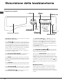
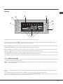
Descrizione della lavabiancheria
Cassetto dei detersivi: per caricare detersivi e additivi
(vedi “Detersivi e biancheria”).
Tasto ON/OFF : premere brevemente il tasto per ac-
cendere o spegnere la macchina. La spia START/PAUSE
che lampeggia lentamente di colore verde indica che la
macchina è accesa. Per spegnere la lavabiancheria du-
rante il lavaggio è necessario tenere premuto il tasto più
a lungo, circa 2 sec.; una pressione breve o accidentale
non permetterà lo spegnimento della macchina.
Lo spegnimento della macchina durante un lavaggio in
corso annulla il lavaggio stesso.
Tasti SELETTORE PROGRAMMI: per impostare il pro-
gramma desiderato (vedi “Tabella dei programmi”).
Tasto MEMO: tenere premuto il tasto per memorizzare
un ciclo e le proprie personalizzazioni preferite. Per richia-
mare un ciclo precedentemente memorizzato premere il
tasto MEMO.
Tasti FUNZIONE: premere il tasto per selezionare la fun-
zione desiderata. Sul display si illuminerà la spia relativa.
Tasto CENTRIFUGA : premere per ridurre o escludere
del tutto la centrifuga; il valore viene indicato nel display.
Tasto TEMPERATURA : premere per ridurre la tem-
peratura; il valore viene indicato nel display.
Tasto BLOCCO TASTI : per attivare il blocco del
pannello di controllo, tenere premuto il tasto per circa
2 secondi. Il simbolo acceso indica che il pannello
di controllo è bloccato. In questo modo si impediscono
modifiche accidentali dei programmi, soprattutto se in
casa ci sono dei bambini.
Per disattivare il blocco del pannello di controllo, tenere
premuto il tasto per circa 2 secondi.
Tasto PARTENZA RITARDATA : premere per impo-
stare una partenza ritardata del programma prescelto; il
ritardo viene indicato nel display.
Tasto con spia START/PAUSE: quando la spia verde
lampeggia lentamente, premere il tasto per avviare un
lavaggio. A ciclo avviato la spia diventa fissa. Per mettere
in pausa il lavaggio, premere nuovamente il tasto; la spia
lampeggerà con colore arancione. Se il simbolo non è
illuminato, si potrà aprire l’oblò. Per far ripartire il lavaggio
dal punto in cui è stato interrotto, premere nuovamente il
tasto.
Modalità di stand by
Questa lavatrice, in conformità alle nuove normative
legate al risparmio energetico, è dotata di un sistema
di autospegnimento (stand by) che entra in funzione
dopo circa 30 minuti nel caso di non utilizzo. Premere
brevemente il tasto ON/OFF e attendere che la macchina
si riattivi.
Tasto con spia
START/
PAUSE
Tasto
TEMPERATURA
Tasto
CENTRIFUGA
Pannello di controllo
Tasto
BLOCCO
TASTI
Tasti
FUNZIONE
Tasto ON/OFF
Tasto
MEMO
Tasto
PARTENZA
RITARDATA
Tasti
SELETTORE
PROGRAMMI
Cassetto dei detersivi
DISPLAY
La pagina si sta caricando...
La pagina si sta caricando...
La pagina si sta caricando...
La pagina si sta caricando...
La pagina si sta caricando...
La pagina si sta caricando...
La pagina si sta caricando...
La pagina si sta caricando...
La pagina si sta caricando...
La pagina si sta caricando...
La pagina si sta caricando...
La pagina si sta caricando...
La pagina si sta caricando...
La pagina si sta caricando...
La pagina si sta caricando...
La pagina si sta caricando...
La pagina si sta caricando...
La pagina si sta caricando...
La pagina si sta caricando...
La pagina si sta caricando...
La pagina si sta caricando...
La pagina si sta caricando...
La pagina si sta caricando...
La pagina si sta caricando...
La pagina si sta caricando...
La pagina si sta caricando...
La pagina si sta caricando...
La pagina si sta caricando...
La pagina si sta caricando...
La pagina si sta caricando...
La pagina si sta caricando...
La pagina si sta caricando...
La pagina si sta caricando...
La pagina si sta caricando...
La pagina si sta caricando...
La pagina si sta caricando...
La pagina si sta caricando...
La pagina si sta caricando...
La pagina si sta caricando...
La pagina si sta caricando...
La pagina si sta caricando...
La pagina si sta caricando...
La pagina si sta caricando...
La pagina si sta caricando...
La pagina si sta caricando...
La pagina si sta caricando...
La pagina si sta caricando...
La pagina si sta caricando...
La pagina si sta caricando...
La pagina si sta caricando...
-
 1
1
-
 2
2
-
 3
3
-
 4
4
-
 5
5
-
 6
6
-
 7
7
-
 8
8
-
 9
9
-
 10
10
-
 11
11
-
 12
12
-
 13
13
-
 14
14
-
 15
15
-
 16
16
-
 17
17
-
 18
18
-
 19
19
-
 20
20
-
 21
21
-
 22
22
-
 23
23
-
 24
24
-
 25
25
-
 26
26
-
 27
27
-
 28
28
-
 29
29
-
 30
30
-
 31
31
-
 32
32
-
 33
33
-
 34
34
-
 35
35
-
 36
36
-
 37
37
-
 38
38
-
 39
39
-
 40
40
-
 41
41
-
 42
42
-
 43
43
-
 44
44
-
 45
45
-
 46
46
-
 47
47
-
 48
48
-
 49
49
-
 50
50
-
 51
51
-
 52
52
-
 53
53
-
 54
54
-
 55
55
-
 56
56
-
 57
57
-
 58
58
-
 59
59
-
 60
60
-
 61
61
-
 62
62
-
 63
63
-
 64
64
-
 65
65
-
 66
66
-
 67
67
-
 68
68
-
 69
69
-
 70
70


HOTPOINT/ARISTON BWMD 742 (EU) Guida utente
- Categoria
- Lavatrici
- Tipo
- Guida utente
in altre lingue
Documenti correlati
-
HOTPOINT/ARISTON WMD 1044BX EU Guida utente
-
HOTPOINT/ARISTON BWMD 742 (EU) Guida utente
-
-
-
Hotpoint-Ariston BWMD 742 (EU) Manuale del proprietario
-
Hotpoint-Ariston WMD 942K EU Manuale del proprietario
-