Genius SPRINT07 SPRINT08 Istruzioni per l'uso
- Categoria
- Gate Opener
- Tipo
- Istruzioni per l'uso

SPRINT 07
24V / 230V
SPRINT 08
24V / 115V
ISTRUZIONI PER L’USO - NORME DI INSTALLAZIONE
INSTRUCTIONS FOR USE - DIRECTIONS FOR INSTALLATION
INSTRUCTIONS - REGLES D’INSTALLATION
INSTRUCCIONES PARA EL USO - NORMAS PARA LA INSTALACION
GEBRAUCHSANLEITUNG - ANWEISUNGEN ZUR INSTALLATION
GEBRUIKSAANWIJZINGEN – INSTALLATIEVOORSCHRIFTEN

AVVERTENZE PER L’INSTALLATORE
OBBLIGHI GENERALI PER LA SICUREZZA
1) ATTENZIONE! È importante per la sicurezza delle persone seguire attentamente
tutta l’istruzione. Una errata installazione o un errato uso del prodotto può portare
a gravi danni alle persone.
2) Leggere attentamente le istruzioni prima di iniziare l’installazione del prodotto.
3) I materiali dell’imballaggio (plastica, polistirolo, ecc.) non devono essere lasciati
alla portata dei bambini in quanto potenziali fonti di pericolo.
4) Conservare le istruzioni per riferimenti futuri.
5) Questo prodotto è stato progettato e costruito esclusivamente per l’utilizzo
indicato in questa documentazione. Qualsiasi altro utilizzo non espressamente
indicato potrebbe pregiudicare l’integrità del prodotto e/o rappresentare fonte
di pericolo.
6) GENIUS declina qualsiasi responsabilità derivata dall’uso improprio o diverso da
quello per cui l’automatismo è destinato.
7) Non installare l’apparecchio in atmosfera esplosiva: la presenza di gas o fumi
infiammabili costituisce un grave pericolo per la sicurezza.
8) Gli elementi costruttivi meccanici devono essere in accordo con quanto stabilito
dalle Norme EN 12604 e EN 12605.
Per i Paesi extra-CEE, oltre ai riferimenti normativi nazionali, per ottenere un livello di
sicurezza adeguato, devono essere seguite le Norme sopra riportate.
9) GENIUS non è responsabile dell’inosservanza della Buona Tecnica nella costru-
zione delle chiusure da motorizzare, nonché delle deformazioni che dovessero
intervenire nell’utilizzo.
10) L’installazione deve essere effettuata nell’osservanza delle Norme EN 12453 e
EN 12445. Il livello di sicurezza dell’automazione deve essere C+D.
11) Prima di effettuare qualsiasi intervento sull’impianto, togliere l’alimentazione
elettrica e scollegare le batterie.
12) Prevedere sulla rete di alimentazione dell’automazione un interruttore onnipolare
con distanza d’apertura dei contatti uguale o superiore a 3 mm. È consigliabile
l’uso di un magnetotermico da 6A con interruzione onnipolare.
13) Verificare che a monte dell’impianto vi sia un interruttore differenziale con
soglia da 0,03 A.
14) Verificare che l’impianto di terra sia realizzato a regola d’arte e collegarvi le
parti metalliche della chiusura.
15) L’automazione dispone di una sicurezza intrinseca antischiacciamento costituita
da un controllo di coppia. E’ comunque necessario verificarne la sogli di intervento
secondo quanto previsto dalle Norme indicate al punto 10.
16) I dispositivi di sicurezza (norma EN 12978) permettono di proteggere eventuali
aree di pericolo da Rischi meccanici di movimento, come ad Es. schiacciamento,
convogliamento, cesoiamento.
17) Per ogni impianto è consigliato l’utilizzo di almeno una segnalazione luminosa
nonché di un cartello di segnalazione fissato adeguatamente sulla struttura
dell’infisso, oltre ai dispositivi citati al punto “16”.
18) GENIUS declina ogni responsabilità ai fini della sicurezza e del buon funziona-
mento dell’automazione, in caso vengano utilizzati componenti dell’impianto
non di produzione GENIUS.
19) Per la manutenzione utilizzare esclusivamente parti originali GENIUS.
20) Non eseguire alcuna modifica sui componenti facenti parte del sistema
d’automazione.
21) L’installatore deve fornire tutte le informazioni relative al funzionamento manuale
del sistema in caso di emergenza e consegnare all’Utente utilizzatore dell’impianto
il libretto d’avvertenze allegato al prodotto.
22) Non permettere ai bambini o persone di sostare nelle vicinanze del prodotto
durante il funzionamento.
23) Tenere fuori dalla portata dei bambini radiocomandi o qualsiasi altro datore di im-
pulso, per evitare che l’automazione possa essere azionata involontariamente.
24) Il transito tra le ante deve avvenire solo a cancello completamente aperto.
25) L’Utente utilizzatore deve astenersi da qualsiasi tentativo di riparazione o d’in-
tervento diretto e rivolgersi solo a personale qualificato.
26) Tutto quello che non è previsto espressamente in queste istruzioni non è
permesso
IMPORTANT NOTICE FOR THE INSTALLER
GENERAL SAFETY REGULATIONS
1) ATTENTION! To ensure the safety of people, it is important that you read all the
following instructions. Incorrect installation or incorrect use of the product could
cause serious harm to people.
2) Carefully read the instructions before beginning to install the product.
3) Do not leave packing materials (plastic, polystyrene, etc.) within reach of
children as such materials are potential sources of danger.
4) Store these instructions for future reference.
5) This product was designed and built strictly for the use indicated in this documen-
tation. Any other use, not expressly indicated here, could compromise the good
condition/operation of the product and/or be a source of danger.
6) GENIUS declines all liability caused by improper use or use other than that for
which the automated system was intended.
7) Do not install the equipment in an explosive atmosphere: the presence of inflam-
mable gas or fumes is a serious danger to safety.
8) The mechanical parts must conform to the provisions of Standards EN 12604
and EN 12605.
For non-EU countries, to obtain an adequate level of safety, the Standards mentioned
above must be observed, in addition to national legal regulations.
9) GENIUS is not responsible for failure to observe Good Technique in the construc-
tion of the closing elements to be motorised, or for any deformation that may
occur during use.
10) The installation must conform to Standards EN 12453 and EN 12445. The safety
level of the automated system must be C+D.
11) Before attempting any job on the system, cut out electrical power and di-
sconnect the batteries.
12) The mains power supply of the automated system must be fitted with an all-pole
switch with contact opening distance of 3mm or greater. Use of a 6A thermal
breaker with all-pole circuit break is recommended.
13) Make sure that a differential switch with threshold of 0.03 A is fitted upstream
of the system.
14) Make sure that the earthing system is perfectly constructed, and connect metal
parts of the means of the closure to it.
15) The automated system is supplied with an intrinsic anti-crushing safety device
consisting of a torque control. Nevertheless, its tripping threshold must be checked
as specified in the Standards indicated at point 10.
16) The safety devices (EN 12978 standard) protect any danger areas against
mechanical movement Risks, such as crushing, dragging, and shearing.
17) Use of at least one indicator-light is recommended for every system, as well
as a warning sign adequately secured to the frame structure, in addition to the
devices mentioned at point “16”.
18) GENIUS declines all liability as concerns safety and efficient operation of the
automated system, if system components not produced by GENIUS are used.
19) For maintenance, strictly use original parts by GENIUS.
20) Do not in any way modify the components of the automated system.
21) The installer shall supply all information concerning manual operation of the
system in case of an emergency, and shall hand over to the user the warnings
handbook supplied with the product.
22) Do not allow children or adults to stay near the product while it is operating.
23) Keep remote controls or other pulse generators away from children, to prevent
the automated system from being activated involuntarily.
24) Transit through the leaves is allowed only when the gate is fully open.
25) The user must not attempt any kind of repair or direct action whatever and
contact qualified personnel only.
26) Anything not expressly specified in these instructions is not permitted.
CONSIGNES POUR L’INSTALLATEUR
RÈGLES DE SÉCURITÉ
1) ATTENTION! Il est important, pour la sécurité des personnes, de suivre à la lettre
toutes les instructions. Une installation erronée ou un usage erroné du produit peut
entraîner de graves conséquences pour les personnes.
2) Lire attentivement les instructions avant d’installer le produit.
3) Les matériaux d’emballage (matière plastique, polystyrène, etc.) ne doivent
pas être laissés à la portée des enfants car ils constituent des sources potentielles
de danger.
4) Conserver les instructions pour les références futures.
5) Ce produit a été conçu et construit exclusivement pour l’usage indiqué dans
cette documentation. Toute autre utilisation non expressément indiquée pourrait
compromettre l’intégrité du produit et/ou représenter une source de danger.
6) GENIUS décline toute responsabilité qui dériverait d’usage impropre ou différent
de celui auquel l’automatisme est destiné.
7) Ne pas installer l’appareil dans une atmosphère explosive: la présence de gaz ou
de fumées inflammables constitue un grave danger pour la sécurité.
8) Les composants mécaniques doivent répondre aux prescriptions des Normes
EN 12604 et EN 12605.
Pour les Pays extra-CEE, l’obtention d’un niveau de sécurité approprié exige non
seulement le respect des normes nationales, mais également le respect des
Normes susmentionnées.
9) GENIUS n’est pas responsable du non-respect de la Bonne Technique dans
la construction des fermetures à motoriser, ni des déformations qui pourraient
intervenir lors de l’utilisation.
10) L’installation doit être effectuée conformément aux Normes EN 12453 et EN
12445. Le niveau de sécurité de l’automatisme doit être C+D.
11) Couper l’alimentation électrique et déconnecter la batterie avant toute
intervention sur l’installation.
12) Prévoir, sur le secteur d’alimentation de l’automatisme, un interrupteur om-
nipolaire avec une distance d’ouverture des contacts égale ou supérieure à 3
mm. On recommande d’utiliser un magnétothermique de 6A avec interruption
omnipolaire.
13) Vérifier qu’il y ait, en amont de l’installation, un interrupteur différentiel avec
un seuil de 0,03 A.
14) Vérifier que la mise à terre est réalisée selon les règles de l’art et y connecter les
pièces métalliques de la fermeture.
15) L’automatisme dispose d’une sécurité intrinsèque anti-écrasement, formée d’un
contrôle du couple. Il est toutefois nécessaire d’en vérifier le seuil d’intervention
suivant les prescriptions des Normes indiquées au point 10.
16) Les dispositifs de sécurité (norme EN 12978) permettent de protéger des zones
éventuellement dangereuses contre les Risques mécaniques du mouvement,
comme l’écrasement, l’acheminement, le cisaillement.
17) On recommande que toute installation soit doté au moins d’une signalisation
lumineuse, d’un panneau de signalisation fixé, de manière appropriée, sur la
structure de la fermeture, ainsi que des dispositifs cités au point “16”.
18) GENIUS décline toute responsabilité quant à la sécurité et au bon fonctionne-
ment de l’automatisme si les composants utilisés dans l’installation n’appartiennent
pas à la production GENIUS.
19) Utiliser exclusivement, pour l’entretien, des pièces GENIUS originales.
20) Ne jamais modifier les composants faisant partie du système d’automatisme.
21) L’installateur doit fournir toutes les informations relatives au fonctionnement
manuel du système en cas d’urgence et remettre à l’Usager qui utilise l’installation
les “Instructions pour l’Usager” fournies avec le produit.
22) Interdire aux enfants ou aux tiers de stationner près du produit durant le
fonctionnement.
23) Eloigner de la portée des enfants les radiocommandes ou tout autre générateur
d’impulsions, pour éviter tout actionnement involontaire de l’automatisme.
24) Le transit entre les vantaux ne doit avoir lieu que lorsque le portail est com-
plètement ouvert.
25) L’Usager qui utilise l’installation doit éviter toute tentative de réparation ou
d’intervention directe et s’adresser uniquement à un personnel qualifié.
26) Tout ce qui n’est pas prévu expressément dans ces instructions est interdit.
ADVERTENCIAS PARA EL INSTALADOR
REGLAS GENERALES PARA LA SEGURIDAD
1) ATENCION! Es sumamente importante para la seguridad de las personas seguir
atentamente las presentes instrucciones. Una instalación incorrecta o un uso
impropio del producto puede causar graves daños a las personas.
2) Lean detenidamente las instrucciones antes de instalar el producto.
3) Los materiales del embalaje (plástico, poliestireno, etc.) no deben dejarse al
alcance de los niños, ya que constituyen fuentes potenciales de peligro.
4) Guarden las instrucciones para futuras consultas.
5) Este producto ha sido proyectado y fabricado exclusivamente para la utilización
indicada en el presente manual. Cualquier uso diverso del previsto podría perjudi-
car el funcionamiento del producto y/o representar fuente de peligro.
6) GENIUS declina cualquier responsabilidad derivada de un uso impropio o

diverso del previsto.
7) No instalen el aparato en atmósfera explosiva: la presencia de gas o humos
inflamables constituye un grave peligro para la seguridad.
8) Los elementos constructivos mecánicos deben estar de acuerdo con lo estable-
cido en las Normas EN 12604 y EN 12605.
Para los países no pertenecientes a la CEE, además de las referencias normativas
nacionales, para obtener un nivel de seguridad adecuado, deben seguirse las
Normas arriba indicadas.
9) GENIUS no es responsable del incumplimiento de las buenas técnicas de fabri-
cación de los cierres que se han de motorizar, así como de las deformaciones
que pudieran intervenir en la utilización.
10) La instalación debe ser realizada de conformidad con las Normas EN 12453 y
EN 12445. El nivel de seguridad de la automación debe ser C+D.
11) Quiten la alimentación eléctrica y desconecten las baterías antes de efectuar
cualquier intervención en la instalación.
12) Coloquen en la red de alimentación de la automación un interruptor omnipolar
con distancia de apertura de los contactos igual o superior a 3 mm. Se aconseja
usar un magnetotérmico de 6A con interrupción omnipolar.
13) Comprueben que la instalación disponga línea arriba de un interruptor dife-
rencial con umbral de 0,03 A.
14) Verifiquen que la instalación de tierra esté correctamente realizada y conecten
las partes metálicas del cierre.
15) La automación dispone de un dispositivo de seguridad antiaplastamiento con-
stituido por un control de par. No obstante, es necesario comprobar el umbral de
intervención según lo previsto en las Normas indicadas en el punto 10.
16) Los dispositivos de seguridad (norma EN 12978) permiten proteger posibles
áreas de peligro de Riesgos mecánicos de movimiento, como por ej. aplasta-
miento, arrastre, corte.
17) Para cada equipo se aconseja usar por lo menos una señalización luminosa
así como un cartel de señalización adecuadamente fijado a la estructura del
bastidor, además de los dispositivos indicados en el “16”.
18) GENIUS declina toda responsabilidad relativa a la seguridad y al buen funcio-
namiento de la automación si se utilizan componentes de la instalación que no
sean de producción GENIUS.
19) Para el mantenimiento utilicen exclusivamente piezas originales GENIUS
20) No efectúen ninguna modificación en los componentes que forman parte del
sistema de automación.
21) El instalador debe proporcionar todas las informaciones relativas al funciona-
miento del sistema en caso de emergencia y entregar al usuario del equipo el
manual de advertencias que se adjunta al producto.
22) No permitan que niños o personas se detengan en proximidad del producto
durante su funcionamiento.
23) Mantengan lejos del alcance los niños los telemandos o cualquier otro emisor
de impulso, para evitar que la automación pueda ser accionada involunta-
riamente.
24) Sólo puede transitarse entre las hojas si la cancela está completamente
abierta.
25) El usuario no debe por ningún motivo intentar reparar o modificar el producto,
debe siempre dirigirse a personal cualificado.
26) Todo lo que no esté previsto expresamente en las presentes instrucciones debe
entenderse como no permitido
HINWEISE FÜR DEN INSTALLATIONSTECHNIKER
ALLGEMEINE SICHERHEITSVORSCHRIFTEN
1) ACHTUNG! Um die Sicherheit von Personen zu gewährleisten, sollte die Anleitung
aufmerksam befolgt werden. Eine falsche Installation oder ein fehlerhafter Betrieb
des Produktes können zu schwerwiegenden Personenschäden führen.
2) Bevor mit der Installation des Produktes begonnen wird, sollten die Anleitungen
aufmerksam gelesen werden.
3) Das Verpackungsmaterial (Kunststoff, Styropor, usw.) sollte nicht in Reichweite von
Kindern aufbewahrt werden, da es eine potentielle Gefahrenquelle darstellt.
4) Die Anleitung sollte aufbewahrt werden, um auch in Zukunft Bezug auf sie
nehmen zu können.
5) Dieses Produkt wurde ausschließlich für den in diesen Unterlagen angegebenen
Gebrauch entwickelt und hergestellt. Jeder andere Gebrauch, der nicht au-
sdrücklich angegeben ist, könnte die Unversehrtheit des Produktes beeinträchtigen
und/oder eine Gefahrenquelle darstellen.
6) Die Firma GENIUS lehnt jede Haftung für Schäden, die durch unsachgemäßen oder
nicht bestimmungsgemäßen Gebrauch der Automatik verursacht werden, ab.
7) Das Gerät sollte nicht in explosionsgefährdeten Umgebungen installiert werden:
das Vorhandensein von entflammbaren Gasen oder Rauch stellt ein schwerwie-
gendes Sicherheitsrisiko dar.
8) Die mechanischen Bauelemente müssen den Anforderungen der Normen EN
12604 und EN 12605 entsprechen.
Für Länder, die nicht der Europäischen Union angehören, sind für die Gewährleistung
eines entsprechenden Sicherheitsniveaus neben den nationalen gesetzlichen
Bezugsvorschriften die oben aufgeführten Normen zu beachten.
9) Die Firma GENIUS übernimmt keine Haftung im Falle von nicht fachgerechten
Ausführungen bei der Herstellung der anzutreibenden Schließvorrichtungen sowie
bei Deformationen, die eventuell beim Betrieb entstehen.
10) Die Installation muß unter Beachtung der Normen EN 12453 und EN 12445
erfolgen. Die Sicherheitsstufe der Automatik sollte C+D sein.
11) Vor der Ausführung jeglicher Eingriffe auf der Anlage sind die elektrische Versor-
gung und die Batterie abzunehmen.
12) Auf dem Versorgungsnetz der Automatik ist ein omnipolarer Schalter mit Öf-
fnungsabstand der Kontakte von über oder gleich 3 mm einzubauen. Darüber
hinaus wird der Einsatz eines Magnetschutzschalters mit 6A mit omnipolarer
Abschaltung empfohlen.
13) Es sollte überprüft werden, ob vor der Anlage ein Differentialschalter mit einer
Auslöseschwelle von 0,03 A zwischengeschaltet ist.
14) Es sollte überprüft werden, ob die Erdungsanlage fachgerecht ausgeführt wurde.
Die Metallteile der Schließung sollten an diese Anlage angeschlossen werden.
15) Die Automation verfügt über eine eingebaute Sicherheitsvorrichtung für den
Quetschschutz, die aus einer Drehmomentkontrolle besteht. Es ist in jedem Falle
erforderlich, deren Eingriffsschwelle gemäß der Vorgaben der unter Punkt 10
angegebenen Vorschriften zu überprüfen.
16) Die Sicherheitsvorrichtungen (Norm EN 12978) ermöglichen den Schutz even-
tueller Gefahrenbereiche vor mechanischen Bewegungsrisiken, wie zum Beispiel
Quetschungen, Mitschleifen oder Schnittverletzungen.
17) Für jede Anlage wird der Einsatz von mindestens einem Leuchtsignal empfohlen
sowie eines Hinweisschildes, das über eine entsprechende Befestigung mit dem
Aufbau des Tors verbunden wird. Darüber hinaus sind die unter Punkt “16” erwähn-
ten Vorrichtungen einzusetzen.
18) Die Firma GENIUS lehnt jede Haftung hinsichtlich der Sicherheit und des störung-
sfreien Betriebs der Automatik ab, soweit Komponenten auf der Anlage eingesetzt
werden, die nicht im Hause GENIUS hergestellt wurden.
19) Bei der Instandhaltung sollten ausschließlich Originalteile der Firma GENIUS
verwendet werden.
20) Auf den Komponenten, die Teil des Automationssystems sind, sollten keine
Veränderungen vorgenommen werden.
21) Der Installateur sollte alle Informationen hinsichtlich des manuellen Betriebs des
Systems in Notfällen liefern und dem Betreiber der Anlage das Anleitungsbuch,
das dem Produkt beigelegt ist, übergeben.
22) Weder Kinder noch Erwachsene sollten sich während des Betriebs in der unmit-
telbaren Nähe der Automation aufhalten.
23) Die Funksteuerungen und alle anderen Impulsgeber sollten außerhalb der
Reichweite von Kindern aufbewahrt werden, um ein versehentliches Aktivieren
der Automation zu vermeiden.
24) Der Durchgang oder die Durchfahrt zwischen den Flügeln darf lediglich bei
vollständig geöffnetem Tor erfolgen.
25) Der Betreiber sollte keinerlei Reparaturen oder direkte Eingriffe auf der Automa-
tion ausführen, sondern sich hierfür ausschließlich an qualifiziertes Fachpersonal
wenden.
26) Alle Vorgehensweisen, die nicht ausdrücklich in der vorliegenden Anleitung
vorgesehen sind, sind nicht zulässig
WAARSCHUWINGEN VOOR DE INSTALLATEUR
ALGEMENE VEILIGHEIDSVOORSCHRIFTEN
1) LET OP! Het is belangrijk voor de veiligheid dat deze hele instructie zorgvuldig
wordt opgevolgd. Een onjuiste installatie of foutief gebruik van het product kunnen
ernstig persoonlijk letsel veroorzaken.
2) Lees de instructies aandachtig door alvorens te beginnen met de installatie
van het product.
3) De verpakkingsmaterialen (plastic, polystyreen, enz.) mogen niet binnen het bereik
van kinderen worden gelaten, want zij vormen een mogelijke bron van gevaar.
4) Bewaar de instructies voor raadpleging in de toekomst.
5) Dit product is uitsluitend ontworpen en gebouwd voor het doel dat in deze
documentatie wordt aangegeven. Elk ander gebruik, dat niet uitdrukkelijk wordt
vermeld, zou het product kunnen beschadigen en/of een bron van gevaar
kunnen vormen.
6) GENIUS aanvaardt geen enkele aansprakelijkheid voor schade die ontstaat uit
oneigenlijk gebruik of ander gebruik dan waarvoor het automatische systeem
is bedoeld.
7) Installeer het apparaat niet in een explosiegevaarlijke omgeving: de aanwe-
zigheid van ontvlambare gassen of dampen vormt een ernstig gevaar voor
de veiligheid.
8) De mechanische bouwelementen moeten in overeenstemming zijn met de
bepalingen van de normen EN 12604 en EN 12605.
Voor niet-EEG landen moeten, om een goed veiligheidsniveau te bereiken,
behalve de nationale voorschriften ook de bovenstaande normen in acht
worden genomen.
9) GENIUS is niet aansprakelijk als de regels der goede techniek niet in acht genomen
zijn bij de bouw van het sluitwerk dat gemotoriseerd moet worden, noch voor
vervormingen die zouden kunnen ontstaan bij het gebruik.
10) De installatie dient te geschieden in overeenstemming met de normen EN
12453 en EN 12445. Het veiligheidsniveau van het automatische systeem moet
C+D zijn.
11) Alvorens ingrepen te gaan verrichten op de installatie moet de elektrische voe-
ding worden weggenomen en moeten de batterijen worden afgekoppeld.
12) Zorg op het voedingsnet van het automatische systeem voor een meerpolige
schakelaar met een opening tussen de contacten van 3 mm of meer. Het wordt
geadviseerd een magnetothermische schakelaar van 6A te gebruiken met
meerpolige onderbreking.
13) Controleer of er bovenstrooms van de installatie een differentieelschakelaar is
geplaatst met een limiet van 0,03 A.
14) Controleer of de aardingsinstallatie vakkundig is aangelegd en sluit er de metalen
delen van het sluitsysteem op aan.
15) Het automatische systeem beschikt over een intrinsieke beveiliging tegen ink-
lemming, bestaande uit een controle van het koppel. De inschakellimiet hiervan
dient echter te worden gecontroleerd volgens de bepalingen van de normen die
worden vermeld onder punt 10.
16) De veiligheidsvoorzieningen (norm EN 12978) maken het mogelijk eventuele ge-
vaarlijke gebieden te beschermen tegen Mechanische gevaren door beweging,
zoals bijvoorbeeld inklemming, meesleuren of amputatie.
17) Het wordt voor elke installatie geadviseerd minstens één lichtsignaal te gebruiken
alsook een waarschuwingsbord dat goed op de constructie van het hang- en
sluitwerk dient te worden bevestigd, afgezien nog van de voorzieningen die
genoemd zijn onder punt “16”.
18) GENIUS aanvaardt geen enkele aansprakelijkheid voor wat betreft de veiligheid
en de goede werking van het automatische systeem, als er in de installatie gebruik
gemaakt wordt van componenten die niet door GENIUS zijn geproduceerd.
19) Gebruik voor het onderhoud uitsluitend originele GENIUS-onderdelen.
20) Verricht geen wijzigingen op componenten die deel uitmaken van het auto-
matische systeem.
21) De installateur dient alle informatie te verstrekken over de handbediening van
het systeem in noodgevallen, en moet de gebruiker van de installatie het bij het
product geleverde boekje met aanwijzingen overhandigen.
22) Sta het niet toe dat kinderen of volwassenen zich ophouden in de buurt van
het product terwijl dit in werking is.
23) Houd radio-afstandsbedieningen of alle andere impulsgevers buiten het bereik
van kinderen, om te voorkomen dat het automatische systeem onopzettelijk kan
worden aangedreven.
24) Ga alleen tussen de vleugels door als het hek helemaal geopend is.
25) De gebruiker mag geen pogingen tot reparatie doen of directe ingrepen plegen,
en dient zich uitsluitend te wenden tot gekwalificeerd personeel.
26) Alles wat niet uitdrukkelijk in deze instructies wordt aangegeven, is niet
toegestaan

11
ENGLISH
CE DECLARATION OF CONFORMITY
Notes on reading the instruction
Read this installation manual to the full before you begin installing the product.
The symbol indicates notes that are important for the safety of persons and for the good condition of the
automated system.
The symbol draws your attention to the notes on the characteristics and operation of the product.
Manufacturer: GENIUS S.p.A.
Address: Via Padre Elzi, 32 - 24050 - Grassobbio- Bergamo - ITALY
Declares that: Control unit mod. SPRINT 07 - SPRINT 08
• conforms to the essential safety requirements of the following EEC directives:
73/23/EEC and subsequent amendment 93/68/EEC.
89/336/EEC and subsequent amendment 92/31/EEC and 93/68/EEC
Additional information:
This product underwent a test in a typical uniform configuration (all products manufactured by GENIUS S.p.A.).
Grassobbio, 01-03-2005
Managing Director
D. Gianantoni
INDEX
1. GENERAL CHARACTERISTICS page.12
2. TECHNICAL SPECIFICATIONS page.1
2
3. PREPARATIONS page.1
2
4. BOARD LAY-OUT page.1
3
5. CONNECTION LAY-OUT page.1
3
6. DESCRIPTION OF CONNECTIONS page.1
4
6.1. TERMINAL-BOARD CN1 page.1
4
6.2. TERMINAL-BOARD CN2 page.1
4
6.3. TERMINAL-BOARD CN3 page.1
4
6.4. TERMINAL-BOARD CN4 page.1
5
6.5. TERMINAL-BOARD CN5 page.1
5
7. OPERATION OF RECEIVER BOARD page.1
5
7.1. SAVING THE CODE page.1
5
7.2. DELETING RADIO CODES page.1
5
8. OPERATION OF ELECTRONIC CLUTCH page.1
6
9. CONTROL LEDs page.1
6
10. ADJUSTING THE OPERATING PARAMETERS page.1
6
11. PROGRAMMING page.1
7
12. PROTECTIVE FUSES page.1
7
13. OPERATING LOGICS page.1
8
14. HOW TO SECURE THE BOARD page.2
0

12
ENGLISH
24 Vdc CONTROL UNIT FOR SLIDING GATES
1. GENERAL CHARACTERISTICS
The SPRINT control unit was designed to control the operation of 24Vdc sliding gates.
Thanks to its built-in electronic clutch device and encoder management, it guarantees - if correctly installed - installation
conforming to the safety regulations in force.
Extremely simple programming of the main functions reduces installation time.
Thanks to the facility for connecting two buffer batteries (optional), any mains power cuts can be overcome. A
waterproof outdoor grade enclosure is available for housing the buffer batteries.
2. TECHNICAL SPECIFICATIONS
Supply voltage of transformer 115/230 V~ (+6 -10%) - 50/60 Hz.
Supply voltage of control unit 22 V~ (+6 -10%) - 50/60 Hz.
Absorbed power 3 W
Motor max. load 70 W
Accessories max load 24Vdc 500mA
Flashing lamp max load 24Vdc 15W max.
Operating ambient temperature -20°C +50°C
Protective fuses 2
Operating logics Automatic / Stepped automatic / Manual / Stepped manual
Opening / closing time Through self-learning during programming
Pause time Through self-learning during programming
Thrust force 4 dip-switch adjustable levels
Deceleration Opening and closing through self-learning
Terminal board inputs
Power supply 22V~ / Batteries power supply / Total opening /
Pedestrian opening / Safety devices / Stop / Limit-switch at opening
/ Limit-switch at closing / Encoder / Antenna
Radio receiver Integrated
Terminal board outputs
Power supply: accessories 24 Vdc / Motors 24 Vdc /
Flashing lamp 24 Vdc
Board dimensions 145 x 105 mm.
Characteristics of 230V~ toroidal transformer prim. 230V~ - sec. 22V~ / 80VA / dimens. Ø105 x 40 mm.
Characteristics of 115V~ toroidal transformer prim. 115V~ - sec. 22V~ / 80VA / dimens. Ø105 x 40 mm.
Characteristics of optional batteries 12V - 4 Ah / dimens. 90 x 70 x 108 mm.
Characteristics of outdoor enclosure 306 x 225 x 130 mm. - IP55
Different output values can be obtained on the 24V~ output depending on the mains voltage value. Before
start-up, always check the transformer output voltage. It must not exceed 26V~ for both power feed values of
230V~ and 115V~. Voltage must be measured load free, i.e. with the transformer powered and disconnected
from the board.
3. PREPARATIONS
To ensure people’s safety, all warnings and instructions in this booklet must be carefully observed. Incorrect
installation or incorrect use of the product could cause serious harm to people.
Make sure there is an adequate differential switch upstream of the system as specified by current safety standards,
and install an omnipolar thermal breaker on the electrical power mains.
• For the installation of power cables: use adequate rigid and/or flexible tubes, always separating low voltage
cables from cables at 230/115 V~. To prevent any interference whatever, use separate sheaths.
• Make sure that the mechanical closing and opening stops are installed.
To secure the various components inside of the airtight enclosure, refer to paragraph 14.

13
ENGLISH
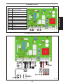
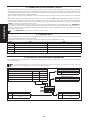
4. BOARD LAY-OUT
5. CONNECTION LAY-OUT
CN1
Terminal-board supplying power
to board/accessories
CN2 Outputs terminal-board
CN3
Terminal-board for encoder and
limit-switch inputs
CN4 Command inputs terminal-board
CN5 Antenna terminal-board
DP1 Dip-switches
F1 Primary power fuse
F2 Accessories fuse
DL1 Power LED
DL2 STOP LED
DL3 FSW LED
DL4 FCC LED
DL5 FCA LED
RX Built-in receiver
Fig. 01
Fig. 02

14
ENGLISH
6. DESCRIPTION OF CONNECTIONS
6.1. TERMINAL-BOARD CN1
6.1.1. Power suPPly 22V~
Terminals “VAC - VAC”. Connect the cables of the transformer’s secondary circuit to these terminals. Mains power
supply “ON” is signalled by the “
POWER” LED located under the terminal-board.
6.1.2. Batteries
Terminals “+BAT / -BAT”. Connect the power cables of the buffer batteries (optional) to these terminals. The control
unit is designed to operate with two buffer batteries with the characteristics shown on the table in paragraph 2.
During normal operation, the control unit keeps the batteries charged - the batteries come into operation in the event of
a mains power cut.
• Power supply from the batteries only should be considered an EMERGENCY situation. The number of possible
manoeuvres is linked to the quality of the batteries, the structure of the gate to be moved, how long ago the
power cut occurred, etc., etc. .
•
The two batteries must be connected to each other in series.
• Observe the polarity of the batteries.
6.1.3. accessories
Terminals “+AAC / -ACC”. Connect the accessories power cables to these terminals.
• The maximum load of the accessories must not exceed 500mA.
• The output of these terminals is on direct power. When connecting the accessories, observe correct
polarity.
6.1.4. earth
Terminal “ ”. Connect the control unit earthing line to this terminal.
• This connection is absolutely necessary to ensure a correctly operating control unit.
6.2. TERMINAL-BOARD CN2
6.2.1. Flashing lamP
Terminals “LAMP / LAMP”. Connect the flashing lamp with 24Vdc max 15W power supply to these terminals.
Before every manoeuvre, the flashing lamp pre-flashes for 0.5 sec.
• We advise you to connect the flashing lamp before programming the board, because it indicates - by a
series of flashes - the different programming stages of both the control unit and the receiver.
• Use a steady beam flashing lamp; flashing is controlled by the control unit itself.
6.2.2. motor
Terminals “CHM1 / APM1”. Connect the motor power cables to these terminals.The maximum load of the motor must
not exceed 70W.
6.3. TERMINAL-BOARD CN3
6.3. encoder
Terminals “SIG / +ENC / -ENC”. Connect, to these terminals: the signal sent from the encoder and the two power
cables.
• The encoder must be connected to ensure operation of the control unit
6.3.2. closure limit switch Fcc
Terminals “COMF / FCC”: Normally closed contact. Connect, to these terminals, the gate closure limit-switch. The switch
intervenes by stopping the gate closing movement. The status of this input is signalled by “
FCC” LED.
6.3.3. oPening limit switch Fca
Terminals “COMF / FCA”. Normally closed contact. Connect, to these terminals, the gate opening limit-switch. The switch
intervenes by stopping the gate opening movement. The status of this input is signalled by “FCA” LED.
• Both limit-switches must be connected to ensure correct operation of the control unit.
• The “
COMF” contact must be used strictly as a common contact of the limit-switches.

15
ENGLISH
6.4. TERMINAL-BOARD CN4
6.4.1. oPen a
Terminals “OPENA / COM2”. Normally open contact. Connect, to these terminals, any pulse generator (e.g. push-button,
selector, etc..) which, by closing the contact, commands the gate to totally open or close. The operation of this input
is defined by dip-switch 5 - see paragraph 10.
• If there are several pulse generators, connect them in parallel.
6.4.2. oPen B
Terminals “OPENB / COM2”. Normally open contact. Connect, to these terminals, any pulse generator (e.g. push-button,
selector, etc..) which, by closing the contact, commands the gate to partially open. Partial opening corresponds to
50% of the total memory-stored opening.
•If there are several pulse generators, connect them in parallel.
6.4.3. stoP
Terminals “STOP / COM2”. Normally closed contact. Connect, to these terminals, any safety device (push-button, pressure
switch etc.) which, by opening the contact, acts on gate motion, causing motion to reverse for 1 second before stopping
movement, by disabling all the automatic functions. The status of this input is signalled by the “STOP” LED.
• If no device is connected, jumper-connect the inputs.
• If several safety devices are present, connect them in series.
6.4.4. Photocells
Terminals “FSW / COM2”. Normally closed contact. Connect, to these terminals, any safety device (photocell, edge,
pressure switch, etc..) which, by opening the contact, acts on gate motion. This input can be active only during the
closing stage or also during the opening stage, according to how dip-switch 4 is selected (see paragraph 10). For the
behaviour of safety devices, see paragraph 13 (operating logics). The status of this input is shown by “FSW” LED.
• If no safety device is connected, jumper-connect the inputs.
6.5. TERMINAL-BOARD CN5
6.5.1. antenna
Connect the external antenna, if any, to these terminals. Connect the antenna cable and the relevant shielding as
shown on the board’s screen-printing.
7. OPERATION OF RECEIVER BOARD
The SPRINT control unit has a built-in receiver board. It operates only with the appropriate remote-controls. For
programming and deleting the radio channel, follow the instructions below.
7.1. SAVING THE CODE
1- Power up the system.
2- Press and hold down “
MEMO RX” push-button. The flashing lamp lights up on steady beam and indicates entry to
the saving stage.
3-
On the remote-control, press the push-button for the channel you wish to save - the flashing lamp flashes to indicate
that the push-button has been saved.
4- Release the radio-control push-button and the “
MEMO RX” push-button: the flashing lamp goes off and you have
exited the saving mode.
5-
To save the next remote-controls, repeat from point 2.
7.2. DELETING RADIO CODES
During the deleting stage, you can delete one channel only or all the saved codes.
7.2.1. deleting a radio code
Procedure for deleting one radio code only:
1- Press and hold down the “MEMO RX” push-button: the flashing lamp lights up on steady beam
2- After 10 seconds, press (on the radio control) the push-button for the channel you wish to delete: the flashing lamp
flashes for 5 seconds.
3- Release the remote control push-button and the “
MEMO RX” push-button on the control unit: the flashing light goes
off.
7.2.2. deleting all radio codes
Procedure for deleting all the saved codes:
1- Press and hold down the “
MEMO RX” push-button: the flashing lamp lights up on steady beam
2- After 30 seconds, press any push-button on the radio control: the flashing lamp flashes for 10 seconds.
3-
Release the remote control push-button and the “
MEMO RX” push-button on the control unit: the flashing lamp
goes off.

16
ENGLISH
8. OPERATION OF ELECTRONIC CLUTCH
This control unit has an electronic clutch device based on the control of the current absorbed by each motor. This
device is extremely important for safety. Its setting is maintained correct long-term and does not require maintenance of
further adjustments. This device is active during both closing and opening. When it operates, it reverses gate movement
without disabling automatic closing if enabled.
The electronic clutch can be adjusted over four sensitivity levels, by using the relevant dip-switches (see paragraph
10).
If the clutch operates two consecutive times, the control unit goes into “
STOP” status, disabling all enabled automatic
functions. This is because, when the clutch operates twice consecutively, it means that the obstacle is still present
and it could be dangerous to perform another manoeuvre. When the obstacle has been removed, you must give an
“OPEN” command to resume the saved cycle.
If the clutch operates three consecutive times, and for more than 120 seconds, the control unit performs an “
EMERGENCY”
procedure: i.e. it executes complete opening until the opening mechanical stop-point is reached, and then closes, if
automatic closing has been enabled. With this manoeuvre, the control unit automatically re-calculates the opening
and closing stop-points.
• The “EMERGENCY” procedure is carried out in slow mode.
9. CONTROL LEDs
There are 5 LEDs on the control unit for controlling inputs and the status of power supplied to the board. The behaviour
of the LEDs is described on the following table.
The
statuses of the LEDs with control unit powered and gate closed are highlighted in bold.
LED ON OFF
DL1 Mains power ON No mains power / battery power
DL2 Stop command released, contact closed Stop command engaged, contact open
DL3 Safety devices released, contact closed Safety devices engaged, contact open
DL4 Closure limit-switch disengaged, contact closed Closure limit-switch engaged, contact open
DL5 Opening limit-switch disengaged, contact closed Opening limit-switch engaged, contact open
10. ADJUSTING THE OPERATING PARAMETERS
The control unit has 6 dip-switches for adjusting operating parameters. The operation of every dip-switch is described
in the table below.
• To avoid damaging the control unit, the dip-switches must be set when the control unit is OFF. The only
exception to this is dip-switch 6 for access to programming.
AUTOMATIC CLOSURE
OFF Automatic closure disabled
ON Automatic closure enabled
OPERATION OF FSW INPUT
OFF Active only for closing
ON Active both for opening and closing
PROGRAMMING
OFF Normal operation
ON
Control unit in programming
mode
ELECTRONIC CLUTCH
Sensitivity Dip-switch 1 Dip-switch 2
Minimum force / maximum sensitivity
OFF OFF
Medium-Low force / medium-high sensitivity
ON OFF
Medium-High force / medium-low sensitivity
OFF ON
Maximum force / minimum sensitivity
ON ON
OPERATION OPEN A PUSH-BUTTON
OFF Opens / Closes / Opens...
ON
Opens / Stops/ Closes / Stops
/ Opens...

17
ENGLISH
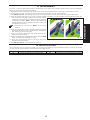
11. PROGRAMMING
The work cycle is programmed entirely in self-learning mode. When the operation parameters have been adjusted,
follow the programming instructions below:
1-
Release the motor, manually open the gate up to half the required extent of opening, and re-lock the motor.
2- Power up the control unit and check if the LEDs are in the situation shown in paragraph 9.
3- Turn
ON dip-switch 6 - the flashing lamp goes on at steady beam to indicate you are in programming stage.
4- Give an opening pulse with one of the connected pulse generators or with the radio-control if already saved. The
first manoeuvre the gate performs must be the closure.
If this does not happen, the control unit must be stopped
operating by doing a “
RESET”, using the appropriate PIN,
as indicated in Fig. 03. Exchange the wires of the motor
and repeat from point 1.
• Remember to re-locate the “RESET” PIN in its initial
position.
5- When the closure limit-switch has been reached, the gate
pauses for about 2 seconds - when this time has elapsed,
the opening manoeuvre begins.
6- When the opening limit-switch has been reached, the
pause time count begins.
7- When the required time has elapsed, supply another
OPEN
pulse, and the gate will begin to close.
8-
When the closure limit-switch has been reached,
programming has finished.
9- Turn
OFF dip-switch 6: the flashing lamp goes off.
12. PROTECTIVE FUSES
The control unit has two protective fuses, one for the power supply to the accessories, and the other for the board
circuits. The fuse characteristics are indicated in the table below.
FUSE CHARACTERISTICS FUSE CHARACTERISTICS
F1 Primary power supply 5x20 T10A 250V F2 Power supply to accessories 5x20 T1.6A 250V
Fig. 03

18
ENGLISH
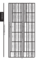
13. OPERATING LOGICS
Automatic logic (Dip-switch 5=OFF Dip-switch 3=ON
Gate status
Pulses
Open A Open B Stop
Safety devices
Dip-switch 4 ON Dip-switch 4 OFF
Closed
Opens gate and closes after
pause time
Partial opening: ~50% of saved
opening
Disables Open commands
Disables Open commands, pens
on release
No
effect
Open in pause Closes immediately Closes immediately Stops operation
Stops operation and, on release,
closes after 3 sec, if pause time
has elapsed
Stops
operation and, on release,
closes after 3 sec, if pause time
has elapsed
Closing Reverses gate movement No effect Stops operation
Stops operation and reverses
after release
Reverses gate movement
Opening No effect No effect Stops operation
Stops operation and restarts
after release
No effect
Automatic Stepped logic (Dip-switch 5=ON Dip-switch3=ON)
Gate status
Pulses
Open A Open B
Stop
Safety devices
Dip-switch 4 ON Dip-switch 4 OFF
Closed
Opens gate and closes after
pause time
Partial opening: ~50% of saved
opening
Disables Open commands
Disables Open commands, opens
on release
No
effect
Open in pause Closes immediately Closes immediately Stops operation
Stops operation and, on release,
closes after 3 sec, if pause time
has elapsed
Stops
operation and, on release,
closes after 3 sec, if pause time
has elapsed
Closing
Stops the gate movement, opens
at successive pulse
No effect Stops operation
Stops operation and reverses
after release
Reverses
gate movement
Opening
Stops the gate movement, closes
at successive pulse
No effect Stops operation
Stops operation and restarts
after release
No effect

19
ENGLISH
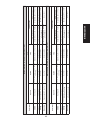
Manual logic (Dip-switch 5=OFF Dip-switch 3=OFF)
Gate status
Pulses
Open A Open B Stop
Safety devices
Dip-switch 4 ON Dip-switch 4 OFF
Closed Opens gate
Partial opening: ~50% of saved
opening
Disables Open commands Disables Open commands Disables Open commands
Open Closes gate Closes gate Stops operation Disables Open commands Disables Open commands
Closing Reverses gate movement No effect Stops operation
Stops operation and reverses
after release
Reverses gate movement
Opening Reverses gate movement No effect Stops operation
Stops operation and restarts
after release
No effect
Manual Stepped logic (Dip-switch 5=ON Dip-switch3=OFF)
Gate status
Pulses
Open A Open B Stop
Safety devices
Dip-switch 4 ON Dip-switch 4 OFF
Closed Opens gate
Partial opening: ~50% of saved
opening
Disables Open commands Disables Open commands Disables Open commands
Open Closes gate Closes gate Stops operation Disables Open commands Disables Open commands
Closing
Stops the gate movement, opens
at successive pulse
No effect Stops operation
Stops operation and reverses
after release
Reverses
gate movement
Opening
Stops the gate movement, closes
at successive pulse
No effect Stops operation
Stops operation and restarts
after release
No
effect

20
ENGLISH
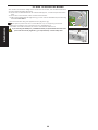
14. HOW TO SECURE THE BOARD
The outdoor enclosure is designed to house the control unit, the toroidal transformer
and any buffer batteries (Optional).
To
secure the toroidal transformer and the board support, consult the specific instruc
-
tions.
To secure the control board, follow the instructions below:
1.
Position the supplied spacers (Fig.03 ref.
a) on the columns identified by the following
letters:
D-L-O-P-R-H-E.
2. Secure the board using the supplied screws (Fig.03 ref.
b).
The spacer positioned next to letter O serve only for supporting the board.
3. Wire up according to the connection lay-out (paragraph 13).
4.
To position and wire the battery kit, refer to the relevant instructions.
If you are using the battery kit, you MUST clear the pre-perforated hole in the lower
part of the enclosure (Fig.04 ref. a) as requested by current safety laws.
Fig. 04
Fig. 05

Le descrizioni e le illustrazioni del presente manuale non sono impegnative. La GENIUS si riserva il diritto, lasciando inalterate le carat-
teristiche essenziali dell’apparecchiatura, di apportare in qualunque momento e senza impegnarsi ad aggiornare la presente pub-
blicazione, le modifiche che essa ritiene convenienti per miglioramenti tecnici o per qualsiasi altra esigenza di carattere costruttivo
o commerciale.
The descriptions and illustrations contained in the present manual are not binding. GENIUS reserves the right, whilst leaving the main
features of the equipments unaltered, to undertake any modifications it holds necessary for either technical or commercial reasons,
at any time and without revising the present publication.
Les descriptions et les illustrations du présent manuel sont fournies à titre indicatif. GENIUS se réserve le droit d’apporter à tout moment
les modifications qu’elle jugera utiles sur ce produit tout en conservant les caractéristiques essentielles, sans devoir pour autant mettre
à jour cette publication.
Die Beschreibungen und Abbildungen in vorliegendem Handbuch sind unverbindlich. GENIUS behält sich das Recht vor, ohne die
wesentlichen Eigenschaften dieses Gerätes zu verändern und ohne Verbindlichkeiten in Bezug auf die Neufassung der vorliegenden
Anleitungen, technisch bzw. konstruktiv/kommerziell bedingte Verbesserungen vorzunehmen.
Las descripciones y las ilustraciones de este manual no comportan compromiso alguno. GENIUS se reserva el derecho, dejando
inmutadas las características esenciales de los aparatos, de aportar, en cualquier momento y sin comprometerse a poner al día la
presente publicación, todas las modificaciones que considere oportunas para el perfeccionamiento técnico o para cualquier otro
tipo de exigencia de carácter constructivo o comercial.
De beschrijvingen in deze handleiding zijn niet bindend. GENIUS behoudt zich het recht voor op elk willekeurig moment de verande-
ringen aan te brengen die het bedrijf nuttig acht met het oog op technische verbeteringen of alle mogelijke andere productie- of
commerciële eisen, waarbij de fundamentele eigenschappen van de apparaat gehandhaafd blijven, zonder zich daardoor te
verplichten deze publicatie bij te werken.
Timbro del Rivenditore:/ Distributor’s Stamp:/ Timbre de l’Agent:/ Fachhändlerstempel:/
Sello del Revendedor:/ Stempel van de dealer:
GENIUS S.p.A.
Via Padre Elzi, 32
24050 Grassobbio (BG) - ITALIA
Tel.: 035/4242511
Fax: 035/4242600
www.geniusg.Com
00058I0612 Rev.1
De beschrijvingen in deze handleiding zijn niet bindend. GENIUS behoudt zich het recht voor op elk willekeurig moment de verande-
ringen aan te brengen die het bedrijf nuttig acht met het oog op technische verbeteringen of alle mogelijke andere productie- of
commerciële eisen, waarbij de fundamentele eigenschappen van de apparaat gehandhaafd blijven, zonder zich daardoor te
verplichten deze publicatie bij te werken.
Timbro del Rivenditore:/ Distributor’s Stamp:/ Timbre de l’Agent:/ Fachhändlerstempel:/
Sello del Revendedor:/ Stempel van de dealer:
-
 1
1
-
 2
2
-
 3
3
-
 4
4
-
 5
5
-
 6
6
-
 7
7
-
 8
8
-
 9
9
-
 10
10
-
 11
11
-
 12
12
-
 13
13
-
 14
14


Genius SPRINT07 SPRINT08 Istruzioni per l'uso
- Categoria
- Gate Opener
- Tipo
- Istruzioni per l'uso
in altre lingue
Documenti correlati
-
Genius SPRINT11SW Istruzioni per l'uso
-
-
-
-
-
-
-
Genius MISTRAL T Istruzioni per l'uso
-
-