
Quick Start Guide
3Com Wireless
802.11a Outdoor Building-to-Building
Bridge and Access Point
3CRWEASYA73 / WL-575
The 3Com WL-575 802.11a Outdoor Building-to-Building Bridge and Access Point provides IEEE
802.11a or 802.11b/g wireless access to the network. The bridge offers a fast, reliable, and cost-
effective solution for connectivity between remote Ethernet wired LANs or to provide Internet access
to an isolated site.
Power is supplied by Power Over Ethernet (PoE) using a:
• 3Com propriety PoE Injector (output: 48V 60W)
About This Guide
This Quick Start Guide describes the basic installation of the bridge. It covers the following topics:
• 3Com WL-575 Outdoor Building-to-Building Bridge and Access Point
• Observing Safety Precautions
• Step 1: Unpacking the Bridge
• Step 2: Preparing for Installation
• Step 3: Mounting the Bridge
• Step 4: Connecting External Antennas
• Step 5: Connecting Cables
• Step 6: Connecting the Power (PoE Injector)
• Step 7: Checking the LED Indicators
• Step 8: Aligning Antennas
• Troubleshooting

2
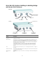
3Com WL-575 Outdoor Building-to-Building Bridge
and Access Point Features
Feature Description
Console Port
Connector
Connect the console cable (included) to the RS-232 console port for accessing the
command-line interface.
POE Connector The PoE port serves two functions, one in providing a means to supply power to the
unit and two as an Ethernet port providing access to the web browser interface.
The Ethernet port provides a 10/100BASE-TX Ethernet connection to a 3Com Wireless
LAN switch. The connection can be direct to a 3Com switch or indirect through an
intermediate Layer 2 or Layer 3 network.
Use a standard Category 5e cable or better with straight-through signaling and
standard RJ-45 connectors to connect the bridge to the switch on the network.
The bridge should be powered via proprietary Power Over Ethernet (PoE) power
injector.
LEDs The LEDs indicate power and activity. See “Checking the LED Indicators” on page 11
for details.
Antenna Connectors Three N-type female antenna connectors allow you to connect antennas that operate
in 2.4 GHz and 5.0 GHz bands.
Water Tight Test
Point
CAUTION: Do not remove or loosen this screw. Doing so could lead to damage of the
unit.
Console Port
Connector
PoE Connector
Integrated Antenna
Bottom View
Top View
N-Type External
Antenna Connector
(2.4 GHz)
N-Type External
Antenna Connector
(5 GHz)
N-Type External
Antenna Connector
(2.4 GHz)
Grounding Point
LEDs
Water Tight Test Point
(DO NOT REMOVE)

3
Observing Safety Precautions
This equipment must be installed in compliance with local and national building codes, regulatory
restrictions, and FCC rules. For the safety of people and equipment, only professional network personnel
should install the bridge.
1 Unpacking the Bridge
Make sure that you have the following items, which are included in the package:
• One 3Com Outdoor 11a Building to Building Bridge and 11bg Access Point
• Mounting bracket and hardware
• One Weatherproof Category 5 network cable
• One Weatherproof Console to RS232 cable
• PoE power injector/ Ethernet connector and AC power cord
• One grounding screw, not attached
•This Quick Start Guide
• One CD-ROM containing the Setup Wizard software and User’s Manual
• One Warranty Flyer
• Optional: One N-type RF coaxial cable
2 Preparing for Installation
It is advisable to connect and check the PoE connection, Ethernet cables, and LEDs before installing the
bridge in a hard-to-reach location. Additionally, observe the following items before mounting or
connecting the bridge:
Grounding Point In the event of electrostatic shock the connection of an insulated cable to the
grounding point to an earthed point protects the unit from excessive electrical
discharge. A grounding screw is provided in the package contents.
Integrated Antenna Built in 5.0 GHz flat panel high-gain antenna.
WARNING: To comply with FCC radio frequency (RF) exposure limits, a minimum body-to-
antenna distance of 20 cm (8 in.) must be maintained when the bridge is operational.
WARNING: To avoid possible injury or damage to equipment, you must use power supply equipment
that is safety certified according to UL, CSA, IEC, or other applicable national or international safety
requirements for the country of use. All references to power supply in this document refer to equipment
meeting these requirements.
Installation Item Description
Cabling Make sure that standard Category 5e cable with straight-through signaling is
installed at the site before you install the bridge.
Power Requirements Power should be supplied via the 3Com proprietary POE injector.

4
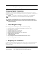
3 Mounting the Bridge
The bridge can be mounted on the following types of surfaces:
•Pole
•Wall
.
Using the Pole-Mounting Bracket
Perform the following steps to mount the unit to a 2 to 3 inch diameter steel pole or tube using the
mounting bracket:
1 Place the V-shaped part of the bracket around the pole and tighten the securing nuts just
enough to hold the bracket to the pole. (The bracket may need to be rotated around the
pole during the antenna alignment process.)
IP Address Record the bridge MAC address in a safe place before the bridge is installed in a
hard-to-reach location.
The MAC address is printed on the back of the bridge. Additional IP address labels
are shipped with the bridge.
Location The WL-575 bridge must only be installed outdoors. It is not for indoor use. The PoE
injector is for indoor use only. Plan your equipment location accordingly.
CAUTION: The bridge is intended for outdoor use only. Do not install the bridge indoors.
V-Shaped bracket

5
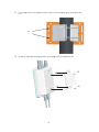
2 Fit the edges of the V-shaped part into the slots in the rectangular plate, and tighten the
nuts.
3 Attach the adjustable rectangular plate to the bridge with the supplied screws.
Slots

6
4 Attach the bridge with bracket to the plate already fixed to the pole.
5 Use the included nuts to secure the wireless bridge to the pole bracket. Note that the
wireless bridge tilt angle may need to be adjusted during the antenna alignment process.
Be sure to take account of the antenna polarization direction; all antennas in a link must be
mounted with the same polarization.
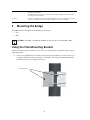
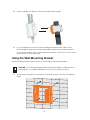
Using the Wall-Mounting Bracket
Perform the following steps to mount the unit to a wall using the wall-mounting bracket:
1 Always attach the bracket to a wall with the flat side flush against the wall (see following
figure).
CAUTION: The wall-mounting bracket does not allow the bridge’s integrated antenna
to be aligned. It is intended for deployment using a 5.0 GHz external antenna.

7
2 Position the bracket in the intended location and mark the position of the four mounting
screw holes.
3 Drill four holes in the wall that match the screws and wall plugs included in the bracket kit,
then secure the bracket to the wall.
4 Use the included nuts to tightly secure the wireless bridge to the bracket.
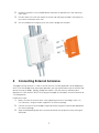
4 Connecting External Antennas
The bridge's primary antenna is it's built-in internal antenna. For some applications when deploying an
WL-575 unit for a bridge link or access point operation, you may need to mount external antennas and
connect them to the bridge. Typically, a bridge link requires a 5.0 GHz antenna, and access point
operation a 2.4
GHz antenna. WL-575 units acting as managed APs also require an external antenna for
2.4 GHz operation.
Perform these steps:
1 Mount the external antenna to the same supporting structure as the bridge, within 3 m
(10
ft) distance, using the bracket supplied in the antenna package.
2 Connect the antenna to the bridge’s N-type connector using the RF coaxial cable provided in
the antenna package.
3 Apply weatherproofing tape to the antenna connectors to help prevent water entering the
connectors.

8
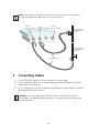
5 Connecting Cables
1 Attach the Ethernet cable to the Ethernet port on the wireless bridge.
2 For extra protection against rain or moisture, apply weatherproofing tape (not included)
around the Ethernet connector.
3 Be sure to ground the unit with an appropriate grounding wire (not included) by attaching it
to the grounding screw on the unit.
NOTE: When you have connected external antennas, be sure to use the management
interface to configure the bridge for correct antenna operation.
CAUTION: Be sure that grounding is available and that it meets local and national
electrical codes. For additional lightning protection, use lightning rods, lightning arrestors,
or surge suppressors.
RF Coaxial Cable
2.4 GHz External
Omnidirectional
Antenna
2.4 GHz
N-type Connector
5 GHz
N-type Connector
5 GHz External
High-gain Panel
Antenna
2.4 GHz
N-type Connector

9
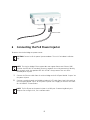
6 Connecting the PoE Power Injector
To connect the wireless bridge to a power source:
1 Connect the Ethernet cable from the wireless bridge to the RJ-45 port labeled “Output” on
the power injector.
2 Connect a straight-through unshielded twisted-pair (UTP) cable from a local LAN switch to
the RJ-45 port labeled “Input” on the power injector. Use Category 5e or better UTP cable
for 10/100BASE-TX connections.
CAUTION: Do not install the power injector outdoors. The unit is for indoor installation
only.
NOTE: The wireless bridge’s Ethernet port does not support Power over Ethernet (PoE)
based on the IEEE 802.3af standard. Do not try to power the unit by connecting it directly
to a network switch that provides IEEE 802.3af PoE. Always connect the unit to the
included power injector.
NOTE: The RJ-45 port on the power injector is an MDI port. If connecting directly to a
computer for testing the link, use a crossover cable.
Ground Wire
Ethernet Cable

10
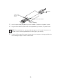
3 Insert the power cable plug directly into the standard AC socket on the power injector.
4 Plug the other end of the power cable into a grounded, 3-pin socket, AC power source.
5 Check the LED on top of the power injector to be sure that power is being supplied to the
wireless bridge through the Ethernet connection.
NOTE: For International use, you may need to change the AC line cord. You must use a
line cord set that has been approved for the socket type in your country.
Input
O
utput
AC power
Power LED indicator
“Input” from
Ethernet Hub/
Switch
“Output” to Bridge

11
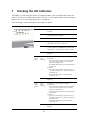
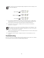
7 Checking the LED Indicators
The bridge’s 11a and 11b/g LEDs operate in two display modes, which are configurable through the
software. The default AP mode indicates data traffic rates. The RSSI mode indicates the received signal
power and is for use when aligning antennas in a bridge link.
When the bridge is connected to power, LEDs indicate as follows:
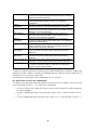
LED Color Indicates
Power Green The bridge is powered up and operating
normally.
Off The bridge is not receiving power or there is a
fault with the power supply.
Amber The system is under cold reset status.
Link Green The bridge has a 10/100 Mbps Fast Ethernet
connection, but there is no activity.
Flashing Indicates that the bridge is transmitting or
receiving data on a 10/100 Mbps Ethernet LAN.
Flashing rate is proportional to network activity.
Off No link is present or the Ethernet LAN port is
disabled.
11a
(Three
LEDs)
Green
and
Flashing
The 802.11a 5.3 GHz radio is enabled.
RSSI Mode:
• One fully lit LED indicates a low RSSI output
level, two LEDs.a medium level, and three
LEDs the maximum level.
• A flashing LED indicates an intermediate RSSI
output level
AP Mode:
• One fully lit LED indicates a low traffic rate,
two LEDs.a medium rate, and three LEDs the
maximum rate.
• A flashing LED indicates an intermediate
traffic rate level
Off No link is present or the 802.11a radio is
disabled.
11g
(Three
LEDs)
Amber
and
Flashing
The 802.11g 2.4 GHz radio is enabled.
RSSI Mode:
• One fully lit LED indicates a low RSSI output
level, two LEDs.a medium level, and three
LEDs the maximum level.
• A flashing LED indicates an intermediate RSSI
output level
AP Mode:
• One fully lit LED indicates a low traffic rate,
two LEDs.a medium rate, and three LEDs the
maximum rate.
• A flashing LED indicates an intermediate
traffic rate level
Off No link is present or the 802.11g radio is
disabled.
11b/g
11a
|||||||||||||||||
Power
Link

12
8 Aligning Antennas
After wireless bridge units have been mounted, connected, and their radios are operating, bridge link
antennas must be accurately aligned to ensure optimum performance. This alignment process is
particularly important for long-range point-to-point links. In a point-to-multipoint configuration the root
bridge uses an omnidirectional or sector antenna, which does not require alignment, but bridge nodes
still need to be correctly aligned with the root bridge antenna.
• Point-to-Point Configurations – In a point-to-point configuration, the alignment process
requires two people, one at each end of the link. The use of cell phones or two-way radio
communication may help with coordination. To start, you can just point the antennas at each
other, using binoculars or a compass to set the general direction. For accurate alignment, you
must monitor the signal strength LEDs as the antenna moves horizontally and vertically.
• Point-to-Multipoint Configurations – In a point-to-multipoint configuration all bridge
nodes must be aligned with the root bridge antenna. The alignment process is the same as in
point-to-point links, but only the bridge node end of the link requires the alignment.
The signal strength LEDs indicate the received radio signal strength for a particular bridge link. The more
LEDs that turn on, the stronger the signal. Alternatively, you can monitor the Receive Signal Strength
Indicator (RSSI) value directly from the management interface. The higher the RSSI value, the stronger
the signal.
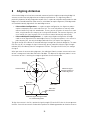
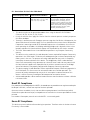
When you move the antenna during alignment, the radio signal from the remote antenna can be seen
to have a strong central main lobe and smaller side lobes. The object of the alignment process is to set
the antenna so that it is receiving the strongest signal from the central main lobe.
To align the antennas in the link, monitor the signal strength LEDs or the RSSI value in the management
interface. Start with one antenna fixed and then perform the following procedure on the other antenna:
Main Lobe
Maximum
Horizontal Scan
Vertical Scan
RSSI
Value
Side Lobe
Maximum
RSSI Value
Remote
Antenna
Maximum Signal Strength Position
for Horizontal Alignment
Maximum Signal
Strength Position for
Vertical Alignment

13
1 Pan the antenna horizontally back and forth while checking the LEDs. If using the pole-
mounting bracket with the unit, you must rotate the mounting bracket around the pole.
Other external antenna brackets may require a different horizontal adjustment.
2 Find the point where the signal is strongest (all LEDs on) and secure the horizontal
adjustment in that position.
3 Loosen the vertical adjustment on the mounting bracket and tilt the antenna slowly up and
down while checking the LEDs.
4 Find the point where the signal is strongest and secure the vertical adjustment in that
position.
Troubleshooting
Refer to the 3Com WL-575 Outdoor Building-to-Building Bridge and Access Point User's Guide or
the 3Com website (www.3Com.com) for troubleshooting information.
Note: The RSSI value can be configured through management interfaces to display a value
for specific WDS bridge links.
Note: Sometimes there may not be a central lobe peak because vertical alignment is too
far off; only two similar peaks for the side lobes are detected. In this case, fix the antenna
so that it is halfway between the two peaks.
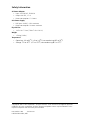
Power
Link
11a
11b/g
Power
Link
11a
11b/g
Power
Link
11a
11b/g
High 11a Signal
Medium 11a Signal
Low 11a Signal

14
Regulatory Information
The 3Com Outdoor 11a Building to Building Bridge and 11bg Access Point, Model WL-575
(3CRWEASYA73) must be installed and used in strict accordance with the manufacturer's
instructions as described in the user documentation that comes with the product.
This product contains encryption. It is unlawful to export out of the U.S. without obtaining a U.S.
Export License.
This product does not contain any user serviceable components. Any unauthorized product changes
or modifications will invalidate 3Com's warranty and all applicable regulatory certifications and
approvals.
Only antennas specified for your region by 3Com can be used with this product. The use of external
amplifiers or non-3Com antennas may invalidate regulatory certifications and approvals.
This product can be used with the following antennas and accessories:
This product must be installed by a professional technician/installer.
Caution: Exposure to Radio Frequency Radiation
This device generates and radiates radio-frequency energy. In order to comply with FCC radio-
frequency exposure guidelines for an uncontrolled environment, this equipment must be installed
and operated while maintaining a minimum body to antenna distance of 20 cm (approximately
8
in.).
The installer of this radio equipment must ensure that the antenna is located or pointed such that it
does not emit RF field in excess of Health Canada limits for the general population; consult Safety
Code 6, obtainable from Health Canada's website www.hc-sc.gc.ca/rpb.
This equipment complies with IC radiation exposure limits set forth for an uncontrolled environment.
End users must follow the specific operating instructions for satisfying RF exposure compliance. This
equipment should be installed and operated with minimum distance 20cm between the radiator and
your body.
This product must maintain a minimum body to antenna distance of 20 cm. Under these conditions
this product will meet the Basic Restriction limits of 1999/519/EC [Council Recommendation of 12
July 1999 on the limitation of exposure of the general public to electromagnetic fields (0 Hz to 300
GHz)].
Item Description Exclusions
- Embedded 5GHz antenna
3CWE591 3Com 6/8dBi Dual-Band Omni Antenna Must be used with 3CWE810,
3CWE811 or 3CWE812.
3CWE596 3Com 18/20dBi Dual-Band Panel
Antenna
Must be used with 3CWE810,
3CWE811 or 3CWE812.
3CWE598 3Com 8/10dBi Dual-Band Panel Antenna Must be used with 3CWE810,
3CWE811 or 3CWE812.
3CWE810 3Com Ultra Low Loss 6-Foot N to N
connector Antenna Cable
3CWE811 3Com Ultra Low Loss 20-Foot N to N
connector Antenna Cable
3CWE812 3Com Ultra Low Loss 50-Foot N to N
connector Antenna Cable

15
US - Radio Frequency Requirements
This device must not be co-located or operated in conjunction with any other antenna or transmitter.
This device is for indoor use only when using channels 36, 40, 44 or 48 in the 5.15 to 5.25 GHz
frequency range.
High power radars are allocated as primary users of the 5.25 to 5.35 GHz and 5.65 to 5.85 GHz
bands. These radar stations can cause interference with and/or damage this device.
US Federal Communications Commission (FCC) EMC Compliance
This equipment has been tested and found to comply with the limits for a Class B digital device,
pursuant to Part 15 of the FCC Rules. These limits are designed to provide reasonable protection
against harmful interference in a residential installation. This equipment generates, uses and can
radiate radio frequency energy and, if not installed and used in accordance with the instructions,
may cause harmful interference to radio communications. However, there is no guarantee that
interference will not occur in a particular installation. If this equipment does cause harmful
interference to radio or television reception, which can be determined by turning the equipment off
and on, the user is encouraged to try to correct the interference by one or more of the following
measures:
• Reorient or relocate the receiving antenna.
• Increase the separation between the equipment and receiver.
• Connect the equipment into an outlet on a circuit different from that to which the receiver is
connected.
• Consult the dealer or an experienced radio/TV technician for help.
The user may find the following booklet prepared by the Federal Communications Commission
helpful:
The Interference Handbook
This booklet is available from the U.S. Government Printing Office, Washington, D.C. 20402.
Stock No. 004-000-0034504.
3Com is not responsible for any radio or television interference caused by unauthorized modification
of the devices included with this 3Com Outdoor 11a Building to Building Bridge and 11bg Access
Point, Model WL-575 (3CRWEASYA73), or the substitution or attachment of connecting cables and
equipment other than specified by 3Com.
The correction of interference caused by such unauthorized modification, substitution or attachment
will be the responsibility of the user.
Changes or modifications not expressly approved by 3Com could void the user's authority to operate
this equipment.
US Manufacturer's FCC Declaration of Conformity
3Com Corporation
350 Campus Drive
Marlborough, MA 01752-3064, USA
(508) 323-5000
Date: December 09, 2007
Declares that the Product:
Brand Name: 3Com Corporation
Model Number: WL-575

16
Equipment Type: 3Com Outdoor 11a Building to Building Bridge and 11bg Access Point
Complies with Part 15 of the FCC rules. Operation is subject to the following two conditions: (1) this
device may not cause harmful interference, and (2) this device must accept any interference received,
including interference that may cause undesired operation.
Industry Canada - RF Compliance
This device complies with RSS 210 of Industry Canada.
Operation is subject to the following two conditions: (1) this device may not cause interference, and
(2) this device must accept any interference, including interference that may cause undesired
operation of this device.
L‘utilisation de ce dispositif est autorisée seulement aux conditions suivantes: (1) il ne doit pas
produire de brouillage et (2) l’utilisateur du dispositif doit étre prêt à accepter tout brouillage
radioélectrique reçu, même si ce brouillage est susceptible de compromettre le fonctionnement du
dispositif.
The term “IC” before the equipment certification number only signifies that the Industry Canada
technical specifications were met.
To reduce potential radio interference to other users, the antenna type and its gain should be so
chosen that the equivalent isotropically radiated power (EIRP) is not more than that required for
successful communication. To prevent radio interference to the licensed service, this device is
intended to be operated indoors and away from windows to provide maximum shielding. Equipment
(or its transmit antenna) that is installed outdoors is subject to licensing.
Pour empecher que cet appareil cause du brouillage au service faisant l’objet d’une licence, il doit
etre utilize a l’interieur et devrait etre place loin des fenetres afin de Fournier un ecram de blindage
maximal. Si le matriel (ou son antenne d’emission) est installe a l’exterieur, il doit faire l’objet d’une
licence.
High power radars are allocated as primary users of the 5.25 to 5.35 GHz and 5.65 to 5.85 GHz
bands. These radar stations can cause interference with and/or damage this device.
This device must not be co-located or operated in conjunction with any other antenna or transmitter.
Industry Canada - Emissions Compliance Statement
This Class B digital apparatus complies with Canadian ICES-003.
Avis de Conformité à la Réglementation d’Industrie Canada
Cet appareil numérique de la classe B est conform à la norme NMB-003 du Canada.
Safety Compliance Notice
This device has been tested and certified according to the following safety standards and is intended
for use only in Information Technology Equipment which has been tested to these or other
equivalent standards:
• UL Standard 60950 (3rd Edition) or 60950-1
• CAN/CSA C22.2 No. 60950 or 60950-1
3Com Outdoor 11a Building to Building Bridge and
11bg Access Point
Model WL-575

17
• IEC 60950-1
• EN 60950-1
EU Compliance
Intended use: IEEE 802.11b/g/a radio LAN device
NOTE: To ensure product operation is in compliance with local regulations, select the country in
which the product is installed. Refer to installation instructions.
This equipment may be operated in
AT BE CY CZ DK EE FI FR
DE GR HU IE IT LV LT LU
MT NL PL PT SK SI ES SE
GB IS LI NO CH BG RO TR
Č
es ky [Czech] 3Com Coporation tímto prohlašuje, že tento RLAN device je v e
shodě se základními požadav ky a dalšími příslušnými ustanov eními
směrnice 1999/5/ES.
Dansk [Danish] Undertegnede 3Com Corporation erklærer herv ed, at f ølgende
udsty r RLAN device ov erholder de v æsentlige krav og øv rige
relev ante krav i direktiv 1999/5/EF.
Deutsch [German] Hiermit erklärt 3Com Corporation, dass sich das Gerät RLAN device
in Übereinstimmung mit den grundlegenden Anf orderungen und den
übrigen einschlägigen Bestimmungen der Richtlinie 1999/5/EG
bef indet.
Eesti [Estonian] Käesolev aga kinnitab 3Com Corporation seadme RLAN device
v astav ust direktiiv i 1999/5/EÜ põhinõuetele ja nimetatud direktiiv ist
tulenevatele teistele asjakohastele sätetele.
English Hereby , 3Com Corporation, declares that this RLAN device is in
compliance with the essential requirements and other relev ant
prov isions of Directiv e 1999/5/EC.
Español [Spanish] Por medio de la presente 3Com Corporation declara que el RLA N
device cumple con los requisitos esenciales y cualesquiera otras
disposiciones aplicables o exigibles de la Directiv a 1999/5/CE.
Ελλην ική [Greek] ΜΕ ΤΗΝ ΠΑΡΟΥΣΑ 3Com Corporation ΔΗ ΛΩΝΕΙ ΟΤΙ RLAN device
ΣΥΜΜΟΡΦΩΝΕΤΑΙ ΠΡΟΣ ΤΙΣ ΟΥΣΙΩΔΕΙΣ ΑΠΑΙΤΗΣΕΙΣ ΚΑΙ ΤΙΣ
ΛΟΙΠΕΣ ΣΧΕΤΙΚΕΣ ΔΙΑΤΑΞΕΙΣ ΤΗΣ ΟΔΗΓΙΑΣ 1999/5/ΕΚ.
Français [French] Par la présente 3Com Corporation déclare que l'appareil RLAN
device est conf orme aux exigences essentielles et aux autres
dispositions pertinentes de la directiv e 1999/5/CE.

18
A copy of the signed Declaration of Conformity can be downloaded from the Product Support web
page for the 3Com Outdoor 11a Building to Building Bridge and 11bg Access Point, Model WL-575
(3CRWEASYA73) at http://www.3com.com.
Also available at http://support.3com.com/doc/WL-575_EU_DOC.pdf
EU - Restrictions for Use in the 2.4GHz band
This device may be operated indoors or outdoors in all countries of the European Community using
the 2.4GHz band: Channels 1 - 13, except where noted below.
• In Italy the end-user must apply for a license from the national spectrum authority to operate
this device outdoors.
• In Belgium outdoor operation is only permitted using the 2.46 - 2.4835 GHz band: Channel
13.
• In France outdoor operation is only permitted using the 2.4 - 2.454 GHz band: Channels 1 - 7.
Italiano [Italian] Con la presente 3Com Corporation dichiara che questo RLAN device
è conf orme ai requisiti essenziali ed alle altre disposizioni pertinenti
stabilite dalla direttiv a 1999/5/CE.
Latv iski [Latv ian] Ar šo 3Com Corporation deklarē, ka RLAN device atbilst Direktīvas
1999/5/EK būtiskajām prasībām un citiem ar to saistītajiem
noteikumiem.
Lietuv ių
[Lithuanian]
Šiuo 3Com Corporation deklaruoja, kad šis RLAN device atitinka
esminius reikalav imus ir kitas 1999/5/EB Direktyv os nuostatas.
Nederlands [Dutch] Hierbij v erklaart 3Com Corporation dat het toestel RLAN device in
ov ereenstemming is met de essentiële eisen en de andere relev ante
bepalingen v an richtlijn 1999/5/EG.
Malti [Maltese] Hawnhekk, 3Com Corporation, jiddikjara li dan RLAN device
jikkonf orma mal-?ti?ijiet essenzjali u ma provv edimenti o?rajn
relev anti li hemm f id-Dirrettiva 1999/5/EC.
Magy ar
[Hungarian]
Alulírott, 3Com Corporation ny ilatkozom, hogy a RLAN device
megf elel a v onatkozó alapv etõ köv etelmény eknek és az 1999/5/EC
irány elv egy éb elõírásainak.
Polski [Polish] Niniejszy m 3Com Corporation oświa dcza, że RLAN device jest
zgodny z zasadniczy mi wy mogami oraz pozostały mi stosowny mi
postanowieniami Dy rekty wy 1999/5/EC.
Português
[Portuguese]
3Com Corporation declara que este RLAN device está conf orme
com os requisitos essenciais e outras disposições da Directiva
1999/5/CE.
Slovensko
[Slov enian]
3Com Corporation izjav lja, da je ta RLAN device v skladu z
bistv enimi zahtev ami in ostalimi relev antnimi določili direktiv e
1999/5/ES.
Slovensky [Slovak] 3Com Corporation týmto vy hlasuje, že RLAN device spĺňa základné
požiadav ky a všetky príslušné ustanov enia Smernice 1999/5/ES.
Suomi [Finnish] 3Com Corporation v akuuttaa täten että RLAN device tyy ppinen laite
on direktiiv in 1999/5/EY oleellisten v aatimusten ja sitä koskev ien
direktiiv in muiden ehtojen mukainen.

19
EU - Restrictions for Use in the 5GHz band
• This device may be not be operated outdoors when using the bands 5150-5350MHz
(Channels 36, 40, 44, 48, 52, 56, 50, 64).
• In Italy the end-user must apply for a license from the national spectrum authority to operate
this device outdoors.
• To remain in conformance with European spectrum usage laws for Wireless LAN operation, the
above 5GHz channel limitations apply. The user should check the current channel of operation.
If operation is occurring outside of the allowable frequencies as listed above, the user must
cease operating the Outdoor 11a Building to Building Bridge and 11bg Access Point at that
location and consult the local technical support staff responsible for the wireless network.
• The 5GHz Turbo mode feature is not allowed for operation in any European Community
country.
• This device must be used with the radar detection feature required for European Community
operation in the 5GHz bands. This device will avoid operating on a channel occupied by any
radar system in the area. The presence of nearby radar operation may result in temporary
interruption in communications of this device. The Bridge/Access Point's radar detection
feature will automatically restart operation on a channel free of radar. You may consult with
the local technical support staff responsible for the wireless network to ensure the Bridge/
Access Point device(s) are properly configured for European Community operation.
• This device employs a radar detection feature required for European Community operation in
the 5GHz bands. This feature must be activated in order to use ad-hoc operation. The
presence of nearby radar operation may result in interruption in communications of this
device. It will be necessary to configure ad-hoc operation on another channel.
• Ad-hoc mode provides a direct communication between two client devices without a Wireless
LAN Access Point.
Brazil RF Compliance
Este produto está homologado pela ANATEL, de acordo com os procedimentos regulamentados pela
Resolução 242/2000, e atende aos requisitos técnicos aplicados.
Opera em caráter secundário, isto é, não tem direito a proteção contra interferência prejudicial,
mesmo de estações do mesmo tipo, e não pode causar interferência a sistemas operando em caráter
primário.
Para maiores informações, consulte o site da ANATEL - www.anatel.gov.br
Korea RF Compliance
This device may cause radio interference during its operation. Therefore service in relation to human
life security is not available.
Allowed Frequency Bands Allowed Channel Numbers Countries
5.15-5.35 & 5.470-
5.725GHz
36, 40, 44, 48, 52, 56, 60, 64,
100, 104, 108, 112, 116, 120,
124, 128, 132, 136, 140
Austria, Belgium, Bulgaria, Cyprus,
Czech Republic, Denmark, Estonia,
Finland, France, Germany, Greece,
Hungary, Iceland, Ireland, Italy, Latvia,
Liechtenstein, Lithuania, Luxembourg,
Malta, Netherlands, Norway, Poland,
Portugal, Slovakia, Slovenia, Spain,
Sweden, Switzerland, U.K.

Copyright © 2007 3Com Corporation. All rights reserved. 3Com and the 3Com logo are registered
trademarks of 3Com Corporation. All other company and product names may be trademarks of the
respective companies with which they are associated.
Part Number: 1001
5231, Revision AA
Published December, 2007
Safety Information
AC Power Adapter
• Input: 100-240 AC, 50-60 Hz
• Output: 48 VDC, 1.2 A
• Power consumption: 13.2 watts
Unit Power Supply
• PoE input: 48 VDC, 0.6 A maximum
• Power consumption: 28 watts maximum
Physical Size
• 19.5 x 19 x 7.4 cm (7.68 x 7.48 x 2.91 in)
Weight
• 1.54 kg (3.4 lbs)
Temperature
• Operating: -40 to 60°C (-40 to 140°F) non-condensing @ 5 to 50°C
• Storage: -55 to 80°C (-67 to 176°F) non-condensing @ 5 to 70°C
-
 1
1
-
 2
2
-
 3
3
-
 4
4
-
 5
5
-
 6
6
-
 7
7
-
 8
8
-
 9
9
-
 10
10
-
 11
11
-
 12
12
-
 13
13
-
 14
14
-
 15
15
-
 16
16
-
 17
17
-
 18
18
-
 19
19
-
 20
20


3com 3CRWEASYA73 Manuale utente
- Tipo
- Manuale utente
- Questo manuale è adatto anche per
in altre lingue
- English: 3com 3CRWEASYA73 User manual