Futuro Futuro
Universal Island-mount Installation Manual
www.FuturoFuturo.com
03.26.2016
V4
V5
V3
V3
F
3a
3a
3i
3a
3b
3d
3h
3d
3c
3e
3f
3g
V3
H
H
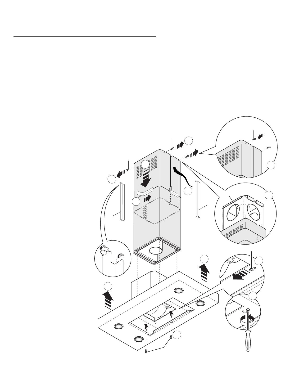
- Alzare la cappa agganciandola alle 4 viti metriche M5 (V4) pre-avvitate al traliccio (C) (centrare i fori Ø11 sull'asola dell'intercamera e traslarla lateralmente) (Fig.
3a)
- Serrare definitivamente le 4 viti M5 (V4) (Fig. 3b).
- Togliere lo scotch di carta (Fig. 3c), togliere le 4 viti metriche M4 (V3) avvitate precedentemente sul traliccio (Fig. 3d) e far scorrere verso il basso l'assieme
camino
prolunga (Fig. 3e).
- Eseguire il collegamento del tubo al raccordo del foro di scarico del soffitto (nel caso di versione aspirante) (Fig. 3f).
- Eseguire il collegamento elettrico solo dopo aver disinserito l'alimentazione elettrica.
- Fissare la prolunga al traliccio (C) tramite le 4 viti metriche M4 (V3), senza bloccarle definitivamente (Fig. 3g).
- Tagliare a misura i copri-fessura (H) ed inserirli (Fig. 3h).
- Bloccare definitivamente la prolunga sul traliccio (C) serrando le 4 viti metriche M4 (V3).
- Bloccare il camino tramite 2 viti auto?lettanti (V5) (Fig. 3i).
- Utilizzare gli elementi supporto prolunga (A) (Fig. 2) solo nel caso non venga usato il traliccio superiore, oppure nel caso di un contro-soffitto.
- Raise the hood, hooking it onto the 4x M5 metric screws (V4) pre-tightened to the lattice-work (C)
(center the Ø11 holes on the slot of the inner liner and move it laterally) (Fig. 3a), then completely
tighten the 4 M5 screws (V4) (Fig. 3b).
- Remove the masking tape (Fig. 3c), remove the four M4 metric screws (V3) previously tightened onto
the lattice-work (Fig. 3d) and slide the flue-extension assembly downwards.
(Fig. 3e).
- Connect the pipe to the connection of the ceiling discharge hole. (Fig. 3f).
- Make electrical connections only after having removed
electrical power supply.
- Fasten the extension to the lattice-work (C) by means
of the 4 M4 metric screws(V3), without
tightening them completely(Fig. 3g).
- (Optional) Cut to size the slot-covers (H)
and insert them (Fig. 3h).
- Secure the extension completely to the
lattice-work (C) by screwing down the 4
M4 metric screws (V3).
- Secure the flue with the 2 self-threading
screws (V5) (Fig. 3i).
- Use the extension support elements (A)
(Fig. 2) only if the upper lattice-work is
not used, or in the case of a false ceiling.
- Levantar la campana sujetándola en los 4
tornillos métricos M5 (V4) previamente
enroscados en el bastidor (C) (centrar los
agujeros Ø11 respecto al orificio ovalado del
intersticio y desplazarla lateralmente) (Fig. 3a)
- Apretar definitivamente los 4 tornillos M5
(V4) (Fig. 3b)
- Quitar el papel adhesivo (Fig. 3c), sacar los 4
tornillos métricos M4 (V3) enroscados con
anterioridad en el bastidor (Fig. 3d) y deslizar
hacia abajo el conjunto chimenea-elemento de
prolongación (Fig. 3e).
- Empalmar el tubo al racor del orificio de
evacuación en el techo (en caso de versión
extractora) (Fig. 3f).
- Realizar la conexión eléctrica sólo después
de haber desconectado la alimentación
eléctrica.
- Fijar el elemento de prolongación en el
bastidor (C) por medio de los 4 tornillos
métricos M4 (V3), sin apretarlos
definitivamente (Fig. 3g)
- Cortar a medida los tapajuntas (H) e
incorporarlos (Fig. 3h)
- Fijar definitivamente el elemento de
prolongación en el bastidor (C) apretando los 4
tornillos métricos M4 (V3).
- Sujetar la chimenea por medio de 2 tornillos
autorroscantes (V5) (Fig. 3i)
- Utilizar los soportes del elemento de
prolongación (A) (Fig. 2) sólo si no se utiliza el
bastidor superior, o también en caso de falso
techo.
Fase 3 / Phase 3 / Fase 3


