
Duramin-40
Instruction Manual
Original Instructions
Doc. no.: 16607025_D_en
Date of release: 2021.02.08

Copyright
The contents of this manual are the property of Struers ApS. Reproduction of any part of this manual
without the written permission of Struers ApS is not allowed.
All rights reserved. © Struers ApS 2021.02.08.
2 Duramin-40

Table of Contents
1 About this manual 6
2 Safety 6
2.1 Intended use 6
2.1.1 Duramin-40safety precautions 7
2.2 Safety messages 8
2.3 Safety messages in this manual 8
3 Getting started 9
3.1 Device description 9
3.2 Overview 10
4 Transport and storage 11
4.1 Transport 11
4.2 Long-term storage or shipping 12
5 Installation 12
5.1 Unpacking 12
5.2 Checking the packing list 13
5.3 Lifting 14
5.4 Location 16
5.5 Placing the machine 17
5.5.1 Removing the transport safety plate 17
5.6 The monitor (option) 18
5.6.1 Contents of the monitor box 18
5.6.2 If you have a two-monitor setup (option) 18
5.7 Mounting an XY-stage 18
5.8 Power supply 20
5.8.1 Connection to the machine 20
5.9 Noise 21
5.10 Vibration 21
6 Operating the device 21
6.1 Main screen 22
6.2 Front panel controls 23
6.3 Starting up Duramin-40 23
6.4 Mounting an indenter 24
6.5 Performing a basic test 25
Duramin-40 3

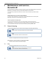
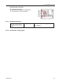
7 Maintenance and service - Duramin-40 26
7.1 General cleaning 26
7.1.1 Daily 26
7.2 Weekly 27
7.2.1 Cleaning the monitor 27
7.2.2 Weekly inspection 27
7.3 Annually 27
7.3.1 Maintenance 27
7.3.2 Testing safety devices 27
7.3.3 Emergency stop 28
7.3.4 Calibration 28
7.4 Service and repair 28
7.4.1 Spare parts 29
7.4.2 Replacing the fuse 29
7.5 Disposal 29
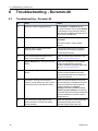
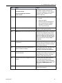
8 Troubleshooting - Duramin-40 30
8.1 Troubleshooting - Duramin-40 30
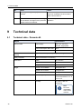
9 Technical data 32
9.1 Technical data - Duramin-40 32
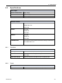
9.2 Specifications 33
9.2.1 Test force 33
9.2.2 Turret 33
9.2.3 System 34
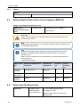
9.3 Safety Related Parts of the Control System (SRP/CS) 34
9.4 Noise and vibration levels 34
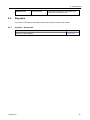
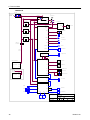
9.5 Diagrams 35
9.5.1 Diagrams - Duramin-40 35
9.6 Legal and regulatory information 37
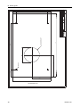
10 Drilling guide 37
10.1 Duramin-40 - Drilling guide 37
11 Pre-installation checklist 39
11.0.1 Installation requirements 40
11.0.2 Packaging specifications 40
11.0.3 Location 40
11.0.4 Dimensions 42
11.0.5 Recommended space 43
11.0.6 Transport and storage 44
11.0.7 Unpacking 45
11.0.8 Lifting 46
4 Duramin-40


1 About this manual
Instruction Manuals
Struers equipment must only be used in connection with and as described in the instruction manual
supplied with the equipment.
Note
Read the instruction manual carefully before use.
Note
If you wish to view specific information in detail, see the online version of this manual.
2 Safety
2.1 Intended use
The intended use is the hardness testing of products. The machine is to be used in an industrial or
laboratory setting. The machine is intended to be used by adult qualified personnel. The machine may
only be operated as described in this manual. The manufacturer is not liable for the damage caused by
incompetent use (unintentional use). Only use the machine when it is technically in good working order
and use it according to the intended use, paying attention to the safety and potential hazards referred to
in this manual.
Manufacturer responsibilities expire when:
• Not or insufficiently complying with the information in this manual.
• Using spare parts or parts not approved by the manufacturer.
• The machine is operated incorrectly.
• Removing, manipulating or not using safety features.
• Changing functions of the machine.
• Unauthorized modifications to the machine are applied.
• Maintenance is not carried out according to instructions.
• The machine is used unintentionally.
Model Duramin-40M1, M2, M3
Duramin-40A1, A2, A3
Duramin-40AC1, AC2, AC3
6 Duramin-40
1 About this manual

2.1.1 Duramin-40safety precautions
Read carefully before use
1. Ignoring this information and mishandling of the equipment can lead to severe bodily injuries
and material damage.
2. The operator must read the safety precautions and Instruction Manual, as well as relevant
sections of the manuals for any connected equipment and accessories.
3. The machine must be installed in compliance with local safety regulations. All functions on the
machine and any connected equipment must be in working order.
4. The machine must be placed on a safe and stable table with an adequate working height.
Failure to do so can affect how the machine works and cause the equipment to drop from the
table and/or cause accidents and injuries.
5. All safety functions must be intact and in working order. If they are not, they must be replaced
or repaired before the machine can be used.
6. Make sure that the actual electrical power supply voltage corresponds to the voltage stated on
the type plate of the machine. Failure to do so can result in the machine catching fire.
7. Do not twist or damage the power cables. Damaged power cables can cause fire and/or
electric shock.
8. Never block the ventilation. The machine can overheat and it can cause fire.
9. Never try to modify this equipment, as doing so can result in fire and/or electric shock.
10. Never try to disassemble this equipment. Doing so can result in electric shock.
11. Never open any panel on the machine while it is turned on. Doing so can result in electric
shock.
12. Do not allow the machine to come into contact with any liquid. The equipment can catch fire if
water or any liquid gets inside it. If water or any other liquid gets inside the machine, turn off the
power, disconnect the power supply and call technical service.
13. Do not connect or disconnect power with wet hands. Doing so can result in electric shock.
14. If you observe malfunctions or hear unusual noises, stop the machine and call technical
service.
15. If two persons work together, make sure they communicate clearly to avoid injuries.
16. Disconnect the machine from the power supply before cleaning it. Failure to do so can result in
electric shock.
17. Struers equipment must only be used in connection with and as described in the instruction
manual supplied with the equipment.
18. If the equipment is subjected to misuse, incorrect installation, alteration, neglect, accident or
incorrect repair, Struers will accept no responsibility for damage to the user or the equipment.
19. Dismantling of any part of the equipment, during service or repair, should always be performed
by a qualified technician (electromechanical, electronic, mechanical, pneumatic, etc.).
2 Safety
Duramin-40 7

2.2 Safety messages
Signs used in safety messages
Struers uses the following signs to indicate potential hazards.
ELECTRICAL HAZARD
This sign indicates an electrical hazard which, if not avoided, will result in death or
serious injury.
DANGER
This sign indicates a hazard with a high level of risk which, if not avoided, will result in
death or serious injury.
WARNING
This sign indicates a hazard with a medium level of risk which, if not avoided, could
result in death or serious injury.
CAUTION
This sign indicates a hazard with a low level of risk which, if not avoided, could result in
minor or moderate injury.
CRUSHING HAZARD
This sign indicates a crushing hazard which, if not avoided, could result in minor,
moderate or serious injury.
General messages
Note
This sign indicates that there is a risk of damage to property, or a need to proceed with
special care.
Hint
This sign indicates that additional information and hints are available.
2.3 Safety messages in this manual
WARNING
Struers equipment must only be used in connection with and as described in the
instruction manual supplied with the equipment.
CRUSHING HAZARD
Take care of your fingers when handling the machine.
Wear safety shoes when handling heavy machinery.
8 Duramin-40
2 Safety

WARNING
Switch off the machine, disconnect the electrical power cable and wait 5 minutes
before you dismantle the machine or install additional components.
ELECTRICAL HAZARD
Switch off the electrical power supply before installing electrical equipment.
The machine must be earthed (grounded).
Make sure that the actual electrical power supply voltage corresponds to the
voltage stated on the type plate of the machine.
Incorrect voltage can damage the electrical circuit.
CAUTION
Prolonged exposure to loud noises may cause permanent damage to a person’s
hearing.
Use hearing protection if the exposure to noise exceeds the levels set by local
regulations.
WARNING
Do not use the machine with defective safety devices.
Contact Struers Service.
WARNING
Before you release the emergency stop, investigate the reason for activating the
emergency stop and take any necessary corrective action.
WARNING
Safety critical components must be replaced after a maximum lifetime of 20 years.
Contact Struers Service.
3 Getting started
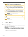
3.1 Device description
Duramin-40 offers a technology base for manual, semi-automatic or fully automated testing of Micro
and Macro Vickers, Knoop or Brinell assignments.
The specimen is placed on the anvil/XY-stage, and the desired testing pattern is set up using the
testing software.
When the test is started, the indenter will move down and indent the specimen with the selected
force.
Following the indentation, the result is obtained by an optical measurement of the indent.
The results can be stored or exported using several formats.
3 Getting started
Duramin-40 9

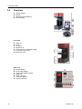
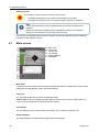
3.2 Overview
AHardness tester
BMonitor
CWireless keyboard (option)
DMouse (option)
Front view
AUSB port
BTurret
CXY-stage
DSpindle cover
EConnection for motorized XY-stage
FZ-axis and focus control
GEmergency stop
Rear view
APower indicator
BPower cable adapter
CPower cable adapter, Monitor
DUSB ports
EHDMI connector
FConnector, Monitor
GInternet connector
10 Duramin-40
3 Getting started

WiFi adapter
For wireless communication with the machine.
USB drive
The USB drive contains calibration documents.
Type plate
The type plate states information about the following:
• Model
• Serial number
• Weight
• Date of manufacture
• Power supply specifications
4 Transport and storage
If, at any time after the installation, you have to move the unit or place it in storage, there is a
number of guidelines we recommend that you follow.
• Package the unit securely before transportation.
Insufficient packaging could cause damage to the unit and will void the warranty. Contact
Struers Service.
• Struers recommends that all original packaging and fittings are kept for future use.
4.1 Transport
• Disconnect the unit from the electrical power supply.
• Disconnect the cable and mount the transport bracket.
• Position a foam block between the indenter and the anvil or XY-stage to prevent them from
moving.
• Mount the lifting bar. See also: Unpacking ►45
• Place the lifting straps securely around the lifting bar. The straps must be approved for at least
twice the weight of the machine.
• Move the machine to the workbench.
4 Transport and storage
Duramin-40 11

4.2 Long-term storage or shipping
Note
Struers recommends that all original packaging and fittings are kept for future use.
• Clean the machine and all accessories thoroughly.
• Disconnect the unit from the electrical power supply.
• Place the machine on the pallet.
• Mount the sides of the crate.
• Place the accessories box, and other loose items in the crate. To keep the machine dry, place a
desiccant (silica gel) in the box, too.
• Mount the lid of the transport box.
At the new location
At the new location, make sure that the facilities required are in place. See also: Location ►40.
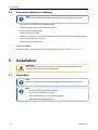
5 Installation
WARNING
Struers equipment must only be used in connection with and as described in the
instruction manual supplied with the equipment.
5.1 Unpacking
Note
Struers recommends that all original packaging and fittings are kept for future use.
Note
• Be careful when you handle the machine.
• Do not drop or damage the machine.
• Do not tilt the packing box more than 30 degrees.
• Be careful not to damage the turret.
12 Duramin-40
5 Installation

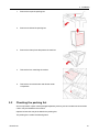
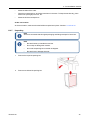
1. Remove the top of the packing box.
2. Remove one side of the packing box.
3. Remove the foam pieces that protect the machine.
4. Take out the box containing the monitor.
5. Take out the accessories box and all other small
components.
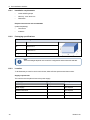
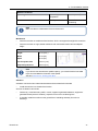
5.2 Checking the packing list
Some components or parts can be packaged separately and may not be included in the accessories
case or may be installed on the machine.
Optional accessories may be included in the packing box.
The packing box contains the following items:
5 Installation
Duramin-40 13

Pcs. Description
1 Duramin-40
1 Accessories case
1 Monitor, 15", (option)
1 Instruction Manual set
Accessories case
Pcs. Description
Indenters
Objective lens
1 Allen key 0.9 mm
1 Z-spindle limiter bracket
1 Mouse, (option)
2 Power supply cables
1 Spare fuse
1 Calibration certificate (on memory stick)
1 WiFi adapter
1 Cable for motorized XY-stage (option)
1 Bluetooth dongle (option)
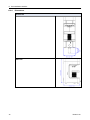
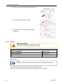
5.3 Lifting
CRUSHING HAZARD
Take care of your fingers when handling the machine.
Wear safety shoes when handling heavy machinery.
Weight
Duramin-40M1/M2/M3 100kg (223 lbs)
Duramin-40A1/A2/A3 112kg (247 lbs)
Duramin-40AC1/AC2/AC3 112kg (247 lbs)
With a crane
Note
The lifting straps must be approved to lift at least twice the weight of the machine.
Use a crane and lifting straps to lift the machine from the packing box.
Make sure that the crane has a free pathway from the lifting point to the workbench.
14 Duramin-40
5 Installation

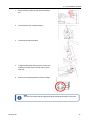
1. Place the lifting straps securely around the lifting
bar.
2. Lift the machine out of the packing box.
3. Lift the machine onto the table.
4. Support the lifting bar and remove the screws and
washers from both sides of the bar using a 5 mm
Allen key.
5. Remove the transport protection of the XY-stage.
Note
Struers recommends that all original packaging and fittings are kept for future use.
5 Installation
Duramin-40 15

5.4 Location
To facilitate easy access for service technicians, allow sufficient space around the machine.
Supply requirements
The machine must be placed close to the power supply.
Supply type Required Not required
Power supply Required
Water supply Not required
Waste water outlet Not required
Compressed air Not required
Exhaust Not required
Ambient conditions
Operating environment Surrounding
temperature
10-35°C (50-95°F)
Humidity 10-90 % RH non-
condensing
Note
Make sure that no condensation forms on the test unit.
Workbench
• Place the machine on a stable and level surface, which can support the weight of the machine.
• Place the machine on a rigid, stable workbench with a horizontal surface and an adequate height.
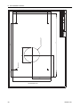
Minimum recommended table dimensions
Height
Width
Depth
1: Ø for spindle hole
2: Spindle protrusion
85cm (33.5")
75cm (20")
60cm (24")
110 mm (4.5")
140 mm (5.5”)
Note
If you wish to use the maximum spindle capacity, you must drill a hole in the table top
to accommodate the full stroke of the spindle.
See also: Duramin-40 - Drilling guide ►49
16 Duramin-40
5 Installation

Vibration
Vibrations can lead to inaccurate measurements and must therefore be avoided.
• Install the machine in a vibration-free location.
Sources of vibration can include:
• Passers-by, a road with heavy traffic, cranes, equipment-generated vibrations, equipment-
generated sound (acoustic vibration), exposure to wind or air conditioning fans.
• If possible, install the machine on the ground floor of a building and away from exits or
doorways.
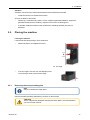
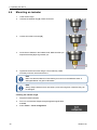
5.5 Placing the machine
Leveling the machine
Level the machine after placing it on the workbench.
• Make sure that the XY-stage/anvil is level.
AXY-stage
• If the XY-stage is not level, turn the adjustment foot
in the rear right corner to level the XY-stage.
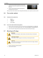
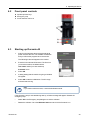
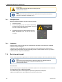
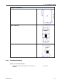
5.5.1 Removing the transport safety plate
Note
Only for motorized XY-stage option.
Remove the transport safety plate before you switch on the machine.
CAUTION
The XY-stage will be damaged if the transport safety plate is not removed before
you switch on the machine.
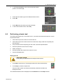
5 Installation
Duramin-40 17

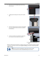
1. Unscrew the six screws securing the transport safety
plate on the rear of the XY-stage. Use an 2.5 mm (0.1")
Allen key.
2. Struers recommends that all original packaging and
fittings are kept for future use.
When you switch on the machine, the XY-stage will automatically move to perform a reference search.
5.6 The monitor (option)
5.6.1 Contents of the monitor box
1 Monitor
1 HDMI cable
1 USB cable
1 Power cables
5.6.2 If you have a two-monitor setup (option)
1. Both the monitors and the ports at the back of the machine are labeled Screen L and Screen R.
2. Connect the correct USB and HDMI cables to the corresponding Screen L and Screen R ports.
3. Connect the power supply cable of the second monitor to the electrical power supply.
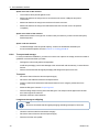
5.7 Mounting an XY-stage
WARNING
If two persons work together, make sure they communicate clearly to avoid injuries.
CRUSHING HAZARD
Do not hold on to the XY-stage or the anvil while you are using the machine.
CAUTION
Always switch off the machine if you need to install or remove an XY-stage, otherwise
the machine can be damaged.
1. Move the Z-spindle to the lowest position.
2. Switch off the machine.
18 Duramin-40
5 Installation

3. Remove the set screws [A] keeping the protecting
bellow in place.
4. Carefully place the stage onto the top of the spindle
[A].
5. Mount the stage using the four fixation screws [A] (the
4th screw is placed on the left side and not visible in
this illustration).
6. Connect the cable to the motorized XY-stage and to
the connection on the left side of the machine.
AConnection for motorized XY-
stage.
Make sure that the Duramin software is configured correctly when a motorized XY-stage is mounted
or removed. In the Duramin software, select System > Settings, and make sure that the option XY-
stage is checked.
Note
The range of force that can be applied is limited when using a XY-stage.
Excessive overload can result in irreparable damage to the machine.
5 Installation
Duramin-40 19

5.8 Power supply
ELECTRICAL HAZARD
Switch off the electrical power supply before installing electrical equipment.
The machine must be earthed (grounded).
Make sure that the actual electrical power supply voltage corresponds to the voltage
stated on the type plate of the machine.
Incorrect voltage can damage the electrical circuit.
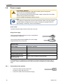
Note
The equipment is shipped with 2 types of electrical power cables. If the plug supplied
on these cables is not approved in your country, the plug must be replaced with an
approved plug. If necessary, use a C14 IEC320 plug.
Power socket
The electrical power supply socket must be easy to access.
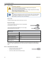
Single-phase supply
The 2-pin plug (European Schuko) is for use on single-phase
electrical power connections.
The 3-pin plug (North American NEMA) is for use on single-
phase electrical power connections.
Electrical data
Power supply 100-240 V, 50/60 Hz
Power, nominal load 82 W
Power, idle 67 W
Current, nominal load 0.35 A
Current, maximum load 0.5 A
Residual Current Circuit
Breaker (RCCB)
Type A, 30 mA (or better) is recommended
Local standards may override the recommendations for the main electrical power supply cable. If
necessary, contact a qualified electrician to verify which option is suitable for the local installation
setup.
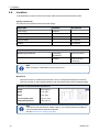
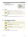
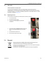
5.8.1 Connection to the machine
• Connect the electrical power cable to the
machine (C14 IEC 320 connector).
• Connect the cable to the electrical power supply.
20 Duramin-40
5 Installation
La pagina si sta caricando...
La pagina si sta caricando...
La pagina si sta caricando...
La pagina si sta caricando...
La pagina si sta caricando...
La pagina si sta caricando...
La pagina si sta caricando...
La pagina si sta caricando...
La pagina si sta caricando...
La pagina si sta caricando...
La pagina si sta caricando...
La pagina si sta caricando...
La pagina si sta caricando...
La pagina si sta caricando...
La pagina si sta caricando...
La pagina si sta caricando...
La pagina si sta caricando...
La pagina si sta caricando...
La pagina si sta caricando...
La pagina si sta caricando...
La pagina si sta caricando...
La pagina si sta caricando...
La pagina si sta caricando...
La pagina si sta caricando...
La pagina si sta caricando...
La pagina si sta caricando...
La pagina si sta caricando...
La pagina si sta caricando...
La pagina si sta caricando...
La pagina si sta caricando...
La pagina si sta caricando...
La pagina si sta caricando...
La pagina si sta caricando...
La pagina si sta caricando...
-
 1
1
-
 2
2
-
 3
3
-
 4
4
-
 5
5
-
 6
6
-
 7
7
-
 8
8
-
 9
9
-
 10
10
-
 11
11
-
 12
12
-
 13
13
-
 14
14
-
 15
15
-
 16
16
-
 17
17
-
 18
18
-
 19
19
-
 20
20
-
 21
21
-
 22
22
-
 23
23
-
 24
24
-
 25
25
-
 26
26
-
 27
27
-
 28
28
-
 29
29
-
 30
30
-
 31
31
-
 32
32
-
 33
33
-
 34
34
-
 35
35
-
 36
36
-
 37
37
-
 38
38
-
 39
39
-
 40
40
-
 41
41
-
 42
42
-
 43
43
-
 44
44
-
 45
45
-
 46
46
-
 47
47
-
 48
48
-
 49
49
-
 50
50
-
 51
51
-
 52
52
-
 53
53
-
 54
54


