Gigabyte B450 Gaming X Manuale del proprietario
- Tipo
- Manuale del proprietario

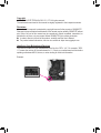
To reduce the impacts on global warming, the packaging materials of this product
are recyclable and reusable. GIGABYTE works with you to protect the environment.
For more product details, please visit GIGABYTE's website.
B450 GAMING X
User's Manual
Rev. 1102
12ME-B45GMX-1102R

Copyright
© 2021 GIGA-BYTE TECHNOLOGY CO., LTD. All rights reserved.
The trademarks mentioned in this manual are legally registered to their respective owners.
Disclaimer
Information in this manual is protected by copyright laws and is the property of GIGABYTE.
Changes to the specications and features in this manual may be made by GIGABYTE without
prior notice. No part of this manual may be reproduced, copied, translated, transmitted, or
published in any form or by any means without GIGABYTE's prior written permission.
In order to assist in the use of this product, carefully read the User's Manual.
For product-related information, check on our website at: https://www.gigabyte.com
Identifying Your Motherboard Revision
The revision number on your motherboard looks like this: "REV: X.X." For example, "REV:
1.0" means the revision of the motherboard is 1.0. Check your motherboard revision before
updating motherboard BIOS, drivers, or when looking for technical information.
Example:

- 3 -
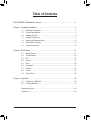
Table of Contents
B450 GAMING X Motherboard Layout ............................................................................4
Chapter 1 Hardware Installation .....................................................................................5
1-1 Installation Precautions .................................................................................... 5
1-2 ProductSpecications ...................................................................................... 6
1-3 Installing the CPU ............................................................................................ 9
1-4 Installing the Memory ....................................................................................... 9
1-5 Installing an Expansion Card ......................................................................... 10
1-6 Back Panel Connectors .................................................................................. 10
1-7 Internal Connectors ........................................................................................ 12
Chapter 2 BIOS Setup ..................................................................................................21
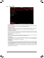
2-1 Startup Screen ............................................................................................... 21
2-2 The Main Menu .............................................................................................. 22
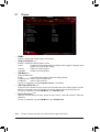
2-3 M.I.T. .............................................................................................................. 23
2-4 System ........................................................................................................... 27
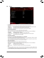
2-5 BIOS ............................................................................................................... 28
2-6 Peripherals ..................................................................................................... 31
2-7 Chipset ........................................................................................................... 34
2-8 Power ............................................................................................................. 36
2-9 Save & Exit ..................................................................................................... 38
Chapter 3 Appendix ......................................................................................................39
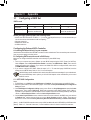
3-1 ConguringaRAIDSet .................................................................................. 39
3-2 DriversInstallation .......................................................................................... 41
RegulatoryNotices .................................................................................................... 42
Contact Us ................................................................................................................ 44

- 4 -
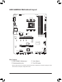
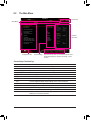
B450 GAMING X Motherboard Layout
* The box contents above are for reference only and the actual items shall depend on the product package you obtain.
The box contents are subject to change without notice.
Box Contents
5B450 GAMING X Motherboard 5User's Manual
5Motherboard driver disc 5Two SATA cables
Socket AM4
AMDB450
R_USB30
CPU_FAN
ATX_12V
ATX
F_AUDIO
AUDIO
PCIEX4
DDR4_2
DDR4_1
DDR4_4
DDR4_3
BAT
F_PANEL
PCIEX1_2
CLR_CMOS
CODEC
M_BIOS
PCIEX1_1
PCIEX16
SPDIF_O
B450 GAMING X
DVI
KB_MS_USB
HDMI
USB_LAN
SATA3
iTE®
Super I/O
LED_C
SYS_FAN1
TPM
M2A_SOCKET
Realtek®
GbE LAN
F_USB30
42
6080
110
LED_CPU
SYS_FAN2
F_USB1
D_LED1
D_LED2
ASATA3 1 0
SATA3 1
0
SYS_FAN3
COMA
2 3

Chapter 1 Hardware Installation
1-1 Installation Precautions
The motherboard contains numerous delicate electronic circuits and components which can become
damagedasaresultofelectrostaticdischarge(ESD).Priortoinstallation,carefullyreadtheuser's
manual and follow these procedures:
•Prior to installation, make sure the chassis is suitable for the motherboard.
•Priortoinstallation,donotremoveorbreakmotherboardS/N(SerialNumber)stickeror
warranty sticker provided by your dealer. These stickers are required for warranty validation.
•Always remove the AC power by unplugging the power cord from the power outlet before
installing or removing the motherboard or other hardware components.
•When connecting hardware components to the internal connectors on the motherboard, make
sure they are connected tightly and securely.
•When handling the motherboard, avoid touching any metal leads or connectors.
•It is best to wear an electrostatic discharge (ESD) wrist strap when handling electronic
componentssuchasamotherboard,CPUormemory.IfyoudonothaveanESDwriststrap,
keepyourhandsdryandrsttouchametalobjecttoeliminatestaticelectricity.
•Prior to installing the motherboard, please have it on top of an antistatic pad or within an
electrostatic shielding container.
•Before connecting or unplugging the power supply cable from the motherboard, make sure
the power supply has been turned off.
•Before turning on the power, make sure the power supply voltage has been set according to
the local voltage standard.
•Before using the product, please verify that all cables and power connectors of your hardware
components are connected.
•To prevent damage to the motherboard, do not allow screws to come in contact with the
motherboard circuit or its components.
•Make sure there are no leftover screws or metal components placed on the motherboard or
within the computer casing.
•Donotplacethecomputersystemonanunevensurface.
•Donotplacethecomputersysteminahigh-temperatureorwetenvironment.
•Turning on the computer power during the installation process can lead to damage to system
components as well as physical harm to the user.
•If you are uncertain about any installation steps or have a problem related to the use of the
product,pleaseconsultacertiedcomputertechnician.
•If you use an adapter, extension power cable, or power strip, ensure to consult with its installation
and/or grounding instructions.
- 5 -

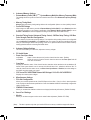
1-2 ProductSpecications
CPU AM4 Socket:
- AMD Ryzen™ 2nd Generation processors
- AMD Ryzen™ with Radeon™ Vega Graphics processors
- AMD Ryzen™ 1st Generation processors
(Go to GIGABYTE's website for the latest CPU support list.)
Chipset AMD B450
Memory 4 x DDR4 DIMM sockets supporting up to 128 GB (32 GB single DIMM capacity)
of system memory
Dual channel memory architecture
Support for DDR4 2933/2667/2400/2133 MHz memory modules
Support for ECC Un-buffered DIMM 1Rx8/2Rx8 memory modules (operate in
non-ECC mode)
Support for non-ECC Un-buffered DIMM 1Rx8/2Rx8/1Rx16 memory modules
Support for Extreme Memory Prole (XMP) memory modules
(Go to GIGABYTE's website for the latest supported memory speeds and memory
modules.)
Onboard
Graphics (Note)
Integrated Graphics Processor:
- 1 x DVI-D port, supporting a maximum resolution of 1920x1200@60 Hz
* The DVI-D port does not support D-Sub connection by adapter.
- 1 x HDMI port, supporting a maximum resolution of 4096x2160@60 Hz (Note)
* Support for HDMI 2.0 version and HDCP 2.2. (Note)
- Maximum shared memory of 16 GB
Audio Realtek® Audio CODEC
High Denition Audio
2/4/5.1/7.1-channel
Support for S/PDIF Out
LAN Realtek® GbE LAN chip (10/100/1000 Mbit)
Expansion Slots 1 x PCI Express x16 slot, running at x16 (PCIEX16) (Note)
* For optimum performance, if only one PCI Express graphics card is to be installed,
be sure to install it in the PCIEX16 slot.
(The PCIEX16 slot conforms to PCI Express 3.0 standard.)
1 x PCI Express x16 slot, running at x4 (PCIEX4)
* The PCIEX4 slot shares bandwidth with the PCIEX1_2 slot. The PCIEX4 slot operates
at up to x2 mode when the PCIEX1_2 slot is populated. The PCIEX4 slot operates
at up to x4 mode when the PCIEX1_2 is empty.
2 x PCI Express x1 slots
(The PCIEX4 and PCIEX1 slots conform to PCI Express 2.0 standard.)
Multi-Graphics
Technology Support for AMD Quad-GPU CrossFire™ and 2-Way AMD CrossFire™ technologies
(Note) Actual support may vary by CPU.
- 6 -

Storage Interface 1 x M.2 connector (Socket 3, M key, type 2242/2260/2280/22110 PCIe 3.0 x4/
x2SSDsupport)
6 x SATA 6Gb/s connectors
SupportforRAID0,RAID1,andRAID10
* Referto"1-7InternalConnectors,"fortheinstallationnoticesfortheM.2andSATA
connectors.
USB Chipset:
- 2 x USB 3.1 Gen 1 ports available through the internal USB header
- 6 x USB 2.0/1.1 ports (4 ports on the back panel, 2 ports available through
theinternalUSBheader)
Integrated in the APU:
- 4 x USB 3.1 Gen 1 ports on the back panel
Internal
Connectors
1 x 24-pin ATX main power connector
1x8-pinATX12Vpowerconnector
1 x M.2 Socket 3 connector
6 x SATA 6Gb/s connectors
1 x CPU fan header
3 x system fan headers
1xCPUcoolerLEDstrip/RGBLEDstripheader
1xRGBLEDstripheader
2xaddressableLEDstripheaders
1 x front panel header
1 x front panel audio header
1xS/PDIFOutheader
1 x USB 3.1 Gen 1 header
1 x USB 2.0/1.1 header
1xTrustedPlatformModule(TPM)header(2x10pin,fortheGC-TPM2.0module
only)
1 x serial port header
1 x Clear CMOS jumper
Back Panel
Connectors
1 x PS/2 keyboard/mouse port
1xDVI-Dport
1xHDMIport
4 x USB 3.1 Gen 1 ports
4 x USB 2.0/1.1 ports
1xRJ-45port
6 x audio jacks
I/O Controller iTE® I/O Controller Chip
- 7 -

Hardware
Monitor
Voltagedetection
Temperature detection
Fan speed detection
Overheating warning
Fan fail warning
Fan speed control
* Whether the fan speed control function is supported will depend on the cooler you
install.
BIOS 1x128Mbitash
Use of licensed AMI UEFI BIOS
PnP1.0a,DMI2.7,WfM2.0,SMBIOS2.7,ACPI5.0
Unique Features Support for APP Center
* Available applications in APP Center may vary by motherboard model. Supported
functionsofeachapplicationmayalsovarydependingonmotherboardspecications.
- @BIOS
- EasyTune
- Fast Boot
- Game Boost
- ON/OFF Charge
- RGBFusion
- Smart Backup
- SystemInformationViewer
SupportforQ-Flash
Support for Xpress Install
Bundled
Software
Norton®InternetSecurity(OEMversion)
Realtek® 8118 Gaming LAN Bandwidth Control Utility
Operating
System Support for Windows 10 64-bit
Form Factor ATX Form Factor; 30.5cm x 23.5cm
* GIGABYTEreservestherighttomakeanychangestotheproductspecicationsandproduct-relatedinformationwithout
prior notice.
Please visit GIGABYTE's website
for support lists of CPU, memory
modules,SSDs,andM.2devices.
Please visit the Support\Utility List
page on GIGABYTE's website to
download the latest version of apps.
- 8 -

1-3 Installing the CPU
Please visit GIGABYTE's website for details on hardware installation.
Dual Channel Memory Conguration
This motherboard provides four memory sockets and supports Dual Channel Technology. After the memory
is installed, the BIOS will automatically detect the specications and capacity of the memory. Enabling Dual
Channel memory mode will double the original memory bandwidth.
The four memory sockets are divided into two channels and each channel has two memory sockets as following:
Channel A: DDR4_2, DDR4_4
Channel B: DDR4_1, DDR4_3
Read the following guidelines before you begin to install the memory:
•Make sure that the motherboard supports the memory. It is recommended that memory of the
same capacity, brand, speed, and chips be used.
(Go to GIGABYTE's website for the latest supported memory speeds and memory modules.)
•Always turn off the computer and unplug the power cord from the power outlet before installing the
memory to prevent hardware damage.
•Memory modules have a foolproof design. A memory module can be installed in only one direction.
If you are unable to insert the memory, switch the direction.
Read the following guidelines before you begin to install the CPU:
•Make sure that the motherboard supports the CPU.
(Go to GIGABYTE's website for the latest CPU support list.)
•Always turn off the computer and unplug the power cord from the power outlet before installing the
CPU to prevent hardware damage.
•Locate the pin one of the CPU. The CPU cannot be inserted if oriented incorrectly.
•Apply an even and thin layer of thermal grease on the surface of the CPU.
•Do not turn on the computer if the CPU cooler is not installed, otherwise overheating and damage
of the CPU may occur.
•Set the CPU host frequency in accordance with the CPU specications. It is not recommended
that the system bus frequency be set beyond hardware specications since it does not meet the
standard requirements for the peripherals. If you wish to set the frequency beyond the standard
specications, please do so according to your hardware specications including the CPU, graphics
card, memory, hard drive, etc.
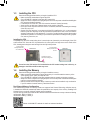
Installing the CPU
Completely lift up the CPU socket locking lever. Locate the pin one (denoted by a small triangle) of the CPU
socket and the CPU. Once the CPU is positioned into its socket, place one nger down on the middle of the
CPU, lowering the locking lever and latching it into the fully locked position.
AM4 Socket
A Small Triangle
Marking Denotes Pin
One of the Socket AM4 CPU
A Small Triangle
Marking Denotes CPU
Pin One
1-4 Installing the Memory
Completely lift up the
CPU socket locking lever
Do not force the CPU into the CPU socket before the CPU socket locking lever is lifted up, or
damage to the CPU and CPU socket may occur.
- 9 -

1-5 Installing an Expansion Card
Readthefollowingguidelinesbeforeyoubegintoinstallanexpansioncard:
•Make sure the motherboard supports the expansion card. Carefully read the manual that came
with your expansion card.
•Always turn off the computer and unplug the power cord from the power outlet before installing an
expansion card to prevent hardware damage.
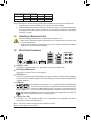
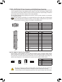
1-6 Back Panel Connectors
USB 2.0/1.1 Port
TheUSBportsupportstheUSB2.0/1.1specication.UsethisportforUSBdevices.
PS/2 Keyboard/Mouse Port
Use this port to connect a PS/2 mouse or keyboard.
DVI-D Port (Note 1)
TheDVI-DportconformstotheDVI-Dspecicationandsupportsamaximumresolutionof1920x1200@60Hz
(theactualresolutionssupporteddependonthemonitorbeingused).ConnectamonitorthatsupportsDVI-D
connection to this port.
HDMI Port
TheHDMIportsupportsHDCP2.2(Note2)andDolbyTrueHDandDTSHDMaster
Audioformats.Italsosupportsupto192KHz/24bit8-channelLPCMaudiooutput.
YoucanusethisporttoconnectyourHDMI-supportedmonitor.Themaximumsupportedresolutionis
4096x2160@60Hz(Note2), but the actual resolutions supported are dependent on the monitor being used.
USB 3.1 Gen 1 Port
TheUSB3.1Gen1portsupportstheUSB3.1Gen1specicationandiscompatibletotheUSB2.0
specication.UsethisportforUSBdevices.
(Note1) TheDVI-DportdoesnotsupportD-Subconnectionbyadapter.
(Note2) ActualsupportmayvarybyCPU.
AfterinstallingtheHDMIdevice,makesuretosetthedefaultsoundplaybackdevicetoHDMI.(The
itemnamemaydifferdependingonyouroperatingsystem.)
DuetoCPUlimitations,readthefollowingguidelinesbeforeinstallingthememoryinDualChannelmode.
1. DualChannelmodecannotbeenabledifonlyonememorymoduleisinstalled.
2. WhenenablingDualChannelmodewithtwoorfourmemorymodules,itisrecommendedthatmemory
of the same capacity, brand, speed, and chips be used. For optimum performance, when enabling
DualChannelmodewithtwomemorymodules,werecommendthatyouinstallthemintheDDR4_1
andDDR4_2sockets.
DualChannelMemoryCongurationsTable
DDR4_4 DDR4_2 DDR4_3 DDR4_1
2 Modules - - DS/SS - - DS/SS
DS/SS - - DS/SS - -
4 Modules DS/SS DS/SS DS/SS DS/SS
(SS=Single-Sided,DS=Double-Sided,"--"=NoMemory)
- 10 -

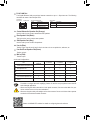
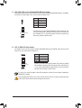
RJ-45 LAN Port
The Gigabit Ethernet LAN port provides Internet connection at up to 1 Gbps data rate. The following
describesthestatesoftheLANportLEDs.
ActivityLED
Connection/
SpeedLED
LAN Port
ActivityLED:Connection/SpeedLED:
State Description
Orange 1 Gbps data rate
Green 100 Mbps data rate
Off 10 Mbps data rate
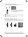
Center/Subwoofer Speaker Out (Orange)
Use this audio jack to connect center/subwoofer speakers.
Rear Speaker Out (Black)
This jack can be used to connect rear speakers.
Side Speaker Out (Gray)
Use this audio jack to connect side speakers.
Line In (Blue)
The line in jack. Use this audio jack for line in devices such as an optical drive, walkman, etc.
Line Out/Front Speaker Out(Green)
The line out jack.
Mic In (Pink)
The Mic in jack.
PleasevisitGIGABYTE'swebsitefordetailsonconguringtheaudiosoftware.
•Whenremovingthecableconnectedtoabackpanelconnector,rstremovethecablefromyour
device and then remove it from the motherboard.
•Whenremovingthecable,pullitstraightoutfromtheconnector.Donotrockitsidetosidetoprevent
an electrical short inside the cable connector.
ToenableorconguretheaudioamplifyingfunctionfortheLineoutjack,pleaseaccesstheHD
Audio Manager application.
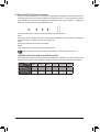
AudioJackCongurations:
Jack Headphone/
2-channel 4-channel 5.1-channel 7.1-channel
Center/Subwoofer Speaker Out a a
RearSpeakerOut a a a
Side Speaker Out a
Line In
Line Out/Front Speaker Out a a a a
Mic In
State Description
Blinking Datatransmissionorreceivingisoccurring
Off No data transmission or receiving is occurring
- 11 -

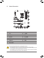
1-7 Internal Connectors
Readthefollowingguidelinesbeforeconnectingexternaldevices:
•First make sure your devices are compliant with the connectors you wish to connect.
•Before installing the devices, be sure to turn off the devices and your computer. Unplug the power
cord from the power outlet to prevent damage to the devices.
•After installing the device and before turning on the computer, make sure the device cable has
been securely attached to the connector on the motherboard.
1) ATX_12V
2) ATX
3) CPU_FAN
4) SYS_FAN1/2/3
5) LED_CPU
6) LED_C
7) D_LED1/D_LED2
8) ASATA3 0/1
9) SATA3 0/1/2/3
10) M2A_SOCKET
11) SPDIF_O
12) F_ PANEL
13) F_ AUDIO
14) BAT
15) CLR_CMOS
16) F_USB30
17) F_USB1
18) COMA
19) TPM
1 4
16
6
10
8
17
15
2
3
9
13 19 124
4
7 18
11
5
7
14 9
- 12 -

DEBUG
PORT
G.QBOFM
131
2412
ATX
1/2) ATX_12V/ATX (2x4 12V Power Connector and 2x12 Main Power Connector)
With the use of the power connector, the power supply can supply enough stable power to all the components
onthemotherboard.Beforeconnectingthepowerconnector,rstmakesurethepowersupplyisturned
off and all devices are properly installed. The power connector possesses a foolproof design. Connect the
power supply cable to the power connector in the correct orientation.
The12VpowerconnectormainlysuppliespowertotheCPU.Ifthe12Vpowerconnectorisnotconnected,
the computer will not start.
To meet expansion requirements, it is recommended that a power supply that can withstand high
powerconsumptionbeused(500Worgreater).Ifapowersupplyisusedthatdoesnotprovidethe
required power, the result can lead to an unstable or unbootable system.
ATX:
Pin No. Denition Pin No. Denition
13.3V 13 3.3V
23.3V 14 -12V
3GND 15 GND
4+5V 16 PS_ON(softOn/Off)
5GND 17 GND
6+5V 18 GND
7GND 19 GND
8 Power Good 20 NC
95VSB(standby+5V) 21 +5V
10 +12V 22 +5V
11 +12V(Only for 2x12-pin
ATX)
23 +5V(Onlyfor2x12-pinATX)
12 3.3V(Onlyfor2x12-pin
ATX)
24 GND(Onlyfor2x12-pinATX)
ATX_12V:
Pin No. Denition Pin No. Denition
1GND(Onlyfor2x4-pin12V) 5+12V(Onlyfor2x4-pin12V)
2GND(Onlyfor2x4-pin12V) 6+12V(Onlyfor2x4-pin12V)
3GND 7+12V
4GND 8+12V
DEBUG
PORT
G.QBOFM
ATX_12V
41
85
3/4) CPU_FAN/SYS_FAN1/2/3 (Fan Headers)
All fan headers on this motherboard are 4-pin. Most fan headers possess a foolproof insertion design.
When connecting a fan cable, be sure to connect it in the correct orientation (the black connector wire is
thegroundwire).Thespeedcontrolfunctionrequirestheuseofafanwithfanspeedcontroldesign.For
optimum heat dissipation, it is recommended that a system fan be installed inside the chassis.
•Be sure to connect fan cables to the fan headers to prevent your CPU and system from
overheating. Overheating may result in damage to the CPU or the system may hang.
•Thesefanheadersarenotcongurationjumperblocks.Donotplaceajumpercapontheheaders.
CPU_FAN
SYS_FAN1
DEBUG
PORT
G.QBOFM
1
DEBUG
PORT
G.QBOFM
1Pin No. Denition
1GND
2VoltageSpeedControl
3 Sense
4 PWM Speed Control
SYS_FAN2
1
DEBUG
PORT
G.QBOFM
SYS_FAN3
DEBUG
PORT
G.QBOFM
1
- 13 -

Pin No. Denition
112V
2 G
3R
4 B
DEBUG
PORT
G.QBOFM
1
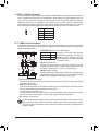
5) LED_CPU (CPU Cooler LED Strip/RGB LED Strip Header)
TheheadercanbeusedtoconnectaCPUcoolerLEDstriporastandard5050RGBLEDstrip(12V/G/R/B),
withmaximumpowerratingof2A(12V)andmaximumlengthof2m.
ConnecttheCPUcoolerLEDstrip/RGBLEDstriptotheheader.The
powerpin(markedwithatriangleontheplug)oftheLEDstripmust
beconnectedtoPin1(12V)ofthisheader.Incorrectconnectionmay
leadtothedamageoftheLEDstrip.
LEDStrip
1
12V
6) LED_C (RGB LED Strip Header)
Theheadercanbeusedtoconnectastandard5050RGBLEDstrip(12V/G/R/B),withmaximumpower
ratingof2A(12V)andmaximumlengthof2m.
Pin No. Denition
112V
2 G
3R
4 B
1
ConnectyourRGBLEDstriptotheheader.Thepowerpin(marked
withatriangleontheplug)oftheLEDstripmustbeconnectedtoPin
1(12V)oftheaddressableLEDstripheader.Incorrectconnection
mayleadtothedamageoftheLEDstrip.
RGB
LEDStrip
1
12V
DEBUG
PORT
G.QBOFM
Before installing the devices, be sure to turn off the devices and your computer. Unplug the power
cord from the power outlet to prevent damage to the devices.
Forhowtoturnon/offthelightsoftheLEDstrippleasevisitthe"UniqueFeatures"webpageof
GIGABYTE's website.
- 14 -

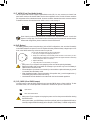
7) D_LED1/D_LED2 (Addressable LED Strip Headers)
Theheaderscanbeusedtoconnectastandard5050addressableLEDstrip,withmaximumpowerrating
of2A(5V)andmaximumlengthof5mormaximumnumberof1000LEDs.
Pin No. Denition
1V
2D
3 No Pin
4 G
Before installing the devices, be sure to turn off the devices and your computer. Unplug the power
cord from the power outlet to prevent damage to the devices.
Forhowtoturnon/offthelightsoftheLEDstrip,refertotheinstructionsoninChapter2,"BIOS
Setup,""Peripherals."
D_LED1 D_LED2
Connectyour addressable LED strip to the header.The powerpin
(markedwithatriangleontheplug)oftheLEDstripmustbeconnected
toPin1oftheaddressableLEDstripheader.Incorrectconnectionmay
leadtothedamageoftheLEDstrip.
1
F_USB30 F_U
B_
F_ F_
_
B
BS_
B
SB_
B
_S
S_
_
B
_U
_
B
S
123
123
123
123
1
1
1
1
BSS
S
_S
SSU
1 2 3 4 5
S3 BSSS
U
__ 3
F_USB3F
S _
S _
S _
SF
B_
B_
F
_0
S
S
_0F
_F
_
_
__B
U
S _S
_ SF_
B
USB0_B
B_ F_USB3
F_USB303
_
_3U
S_
F_USB30 F_U
B_
F_ F_
_
B
BS_
B
SB_
B
_S
S_
_
B
_U
_
B
S
123
123
123
123
1
1
1
1
BSS
S
_S
SSU
1 2 3 4 5
S3 BSSS
U
__ 3
F_USB3F
S _
S _
S _
SF
B_
B_
F
_0
S
S
_0F
_F
_
_
__B
U
S _S
_ SF_
B
USB0_B
B_ F_USB3
F_USB303
_
_3U
S_
1
Addressable
LEDStrip
1
8/9) ASATA3 0/1, SATA 3 0/1/2/3 (SATA 6Gb/s Connectors)
The SATA connectors conform to SATA 6Gb/s standard and are compatible with SATA 3Gb/s and
SATA 1.5Gb/s standard. Each SATA connector supports a single SATA device. The SATA connectors
supportRAID0,RAID1,andRAID10.RefertoChapter3,"ConguringaRAIDSet,"forinstructions
onconguringaRAIDarray.
Pin No. Denition
1GND
2 TXP
3 TXN
4GND
5RXN
6RXP
7GND
SATA3ASATA3
7
1
DEBUG
PORT
G.QBOFM
DEBUG
PORT
G.QBOFM
0
1
SATA3 1
0
DEBUG
PORT
G.QBOFM
DEBUG
PORT
G.QBOFM
7
7
1
1
7
1
DEBUG
PORT
G.QBOFM
DEBUG
PORT
G.QBOFM
3
2
- 15 -

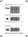
10) M2A_SOCKET (M.2 Socket 3 Connector)
TheM.2connectorsupportsM.2PCIeSSDsandsupportRAIDconguration.PleasenotethatanM.2
PCIeSSDcannotbeusedtocreateaRAIDsetwithaSATAharddrive.TocreateaRAIDarraywithan
M.2PCIeSSD,youmustsetupthecongurationinUEFIBIOSmode.RefertoChapter3,"Conguringa
RAIDSet,"forinstructionsonconguringaRAIDarray.
SelecttheproperholefortheM.2SSDtobeinstalledandrefastenthescrewandnut.
F_USB30 F_U
B_
F_ F_
_
B
BS_
B
SB_
B
_S
S_
_
B
_U
_
B
S
123
123
123
123
1
1
1
1
BSS
S
_S
SSU
1 2 3 4 5
S3 BSSS
U
__ 3
F_USB3F
S _
S _
S _
SF
B_
B_
F
_0
S
S
_0F
_F
_
_
__B
U
S _S
_ SF_
B
USB0_B
B_ F_USB3
F_USB303
_
_3U
S_
80110 60 42
FollowthestepsbelowtocorrectlyinstallanM.2SSDintheM.2connector.
Step 1:
Use a screw driver to unfasten the screw and nut from the motherboard. Locate the proper mounting hole
fortheM.2SSDtobeinstalledandthenscrewthenutrst.
Step 2:
SlidetheM.2SSDintotheconnectoratanangle.
Step 3:
PresstheM.2SSDdownandthensecureitwiththescrew.
Installation Notices for the M.2 and SATA Connectors:
DuetothelimitednumberoflanesprovidedbytheChipset,theavailabilityoftheSATAconnectorsmay
beaffectedbythetypeofdeviceinstalledintheM.2connector.Refertothefollowingtablefordetails.
SATA3 0 SATA3 1 SATA3 2 SATA3 3 ASATA3 0 ASATA3 1
M.2PCIeSSD
a a a a r r
NoM.2SSDInstalled aaaaaa
a: Available, r: Not available
Connector
Type of
M.2SSD
- 16 -

11) SPDIF_O (S/PDIF Out Header)
ThisheadersupportsdigitalS/PDIFOutandconnectsaS/PDIFdigitalaudiocable(providedbyexpansion
cards)fordigitalaudiooutputfromyourmotherboardtocertainexpansioncardslikegraphicscardsand
soundcards.Forexample,somegraphicscardsmayrequireyoutouseaS/PDIFdigitalaudiocablefor
digitalaudiooutputfromyourmotherboardtoyourgraphicscardifyouwishtoconnectanHDMIdisplay
tothegraphicscardandhavedigitalaudiooutputfromtheHDMIdisplayatthesametime.Forinformation
aboutconnectingtheS/PDIFdigitalaudiocable,carefullyreadthemanualforyourexpansioncard.
1
F_USB30 F_U
B_
F_ F_
_
B
BS_
B
SB_
B
_S
S_
_
B
_U
_
B
S
123
123
123
123
1
1
1
1
BSS
S
_S
SSU
1 2 3 4 5
S3 BSSS
U
__ 3
F_USB3F
S _
S _
S _
SF
B_
B_
F
_0
S
S
_0F
_F
_
_
__B
U
S _S
_ SF_
B
USB0_B
B_ F_USB3
F_USB303
_
_3U
S_
Pin No. Denition
15VDUAL
2 No Pin
3SPDIFO
4GND
The front panel design may differ by chassis. A front panel module mainly consists of power switch,
resetswitch,powerLED,harddriveactivityLED,speakerandetc.Whenconnectingyourchassis
front panel module to this header, make sure the wire assignments and the pin assignments are
matched correctly.
12) F_PANEL (Front Panel Header)
Connect the power switch, reset switch, speaker, chassis intrusion switch/sensor and system status indicator
on the chassis to this header according to the pin assignments below. Note the positive and negative pins
before connecting the cables.
System Status LED
S0 On
S3/S4/S5 Off
Connects to the power status indicator
onthechassisfrontpanel.TheLEDison
whenthesystemisoperating.TheLEDis
off when the system is in S3/S4 sleep state
orpoweredoff(S5).
•PW(PowerSwitch,Red):
Connects to the power switch on the chassis front panel. You may
congurethewaytoturnoffyoursystemusingthepowerswitch(refer
toChapter2,"BIOSSetup,""Power,"formoreinformation).
•SPEAK (Speaker,Orange):
Connects to the speaker on the chassis front panel. The system reports
system startup status by issuing a beep code. One single short beep
will be heard if no problem is detected at system startup.
•PLED/PWR_LED (PowerLED,Yellow/Purple):
•HD (HardDriveActivityLED,Blue):
ConnectstotheharddriveactivityLEDonthechassisfrontpanel.TheLEDisonwhentheharddrive
is reading or writing data.
•RES (ResetSwitch,Green):
Connects to the reset switch on the chassis front panel. Press the reset switch to restart the computer
ifthecomputerfreezesandfailstoperformanormalrestart.
•CI (ChassisIntrusionHeader,Gray):
Connects to the chassis intrusion switch/sensor on the chassis that can detect if the chassis cover has
been removed. This function requires a chassis with a chassis intrusion switch/sensor.
•NC (Orange):NoConnection.
PowerLED
DEBUG
PORT
G.QBOFM
1
2
19
20
CI-
CI+
PWR_LED-
PWR_LED+
PLED-
PW-
SPEAK+
SPEAK-
PLED+
PW+
PowerLED
HD-
RES+
HD+
RES-
HardDrive
ActivityLED
Reset
Switch Chassis Intrusion
Header
Power Switch Speaker
PWR_LED-
NC
NC
- 17 -

13) F_AUDIO (Front Panel Audio Header)
ThefrontpanelaudioheadersupportsHighDenitionaudio(HD).Youmayconnectyourchassisfront
panel audio module to this header. Make sure the wire assignments of the module connector match the
pin assignments of the motherboard header. Incorrect connection between the module connector and the
motherboard header will make the device unable to work or even damage it.
Some chassis provide a front panel audio module that has separated connectors on each wire
instead of a single plug. For information about connecting the front panel audio module that has
different wire assignments, please contact the chassis manufacturer.
F_USB30 F_U
B_
F_ F_
_
B
BS_
B
SB_
B
_S
S_
_
B
_U
_
B
S
123
123
123
123
1
1
1
1
BSS
S
_S
SSU
1 2 3 4 5
S3 BSSS
U
__ 3
F_USB3F
S _
S _
S _
SF
B_
B_
F
_0
S
S
_0F
_F
_
_
__B
U
S _S
_ SF_
B
USB0_B
B_ F_USB3
F_USB303
_
_3U
S_
9 1
10 2
Pin No. Denition Pin No. Denition
1MIC2_L 6 Sense
2GND 7FAUDIO_JD
3MIC2_R 8 No Pin
4 NC 9 LINE2_L
5LINE2_R 10 Sense
14) BAT (Battery)
Thebatteryprovidespowertokeepthevalues(suchasBIOScongurations,date,andtimeinformation)
intheCMOSwhenthecomputeristurnedoff.Replacethebatterywhenthebatteryvoltagedropstoalow
level, or the CMOS values may not be accurate or may be lost.
You may clear the CMOS values by removing the battery:
1. Turn off your computer and unplug the power cord.
2. Gently remove the battery from the battery holder and wait for one minute. (Or use a
metal object like a screwdriver to touch the positive and negative terminals of the battery
holder,makingthemshortfor5seconds.)
3. Replacethebattery.
4. Plug in the power cord and restart your computer.
•Always turn off your computer and unplug the power cord before replacing the battery.
•Replacethebatterywithanequivalentone.Damagetoyourdevicesmayoccurifthebatteryis
replaced with an incorrect model.
•Contact the place of purchase or local dealer if you are not able to replace the battery by yourself
or uncertain about the battery model.
•Wheninstallingthebattery,notetheorientationofthepositiveside(+)andthenegativeside(-)
ofthebattery(thepositivesideshouldfaceup).
•Used batteries must be handled in accordance with local environmental regulations.
15) CLR_CMOS (Clear CMOS Jumper)
UsethisjumpertocleartheBIOScongurationandresettheCMOSvaluestofactorydefaults.Toclear
the CMOS values, use a metal object like a screwdriver to touch the two pins for a few seconds.
•Always turn off your computer and unplug the power cord from the power outlet before clearing
the CMOS values.
•Aftersystemrestart,gotoBIOSSetuptoloadfactorydefaults(selectLoadOptimizedDefaults)or
manuallyconguretheBIOSsettings(refertoChapter2,"BIOSSetup,"forBIOScongurations).
Open: Normal
Short:ClearCMOSValues
- 18 -

Pin No. Denition Pin No. Denition
1VBUS 11 D2+
2SSRX1- 12 D2-
3SSRX1+ 13 GND
4GND 14 SSTX2+
5 SSTX1- 15 SSTX2-
6SSTX1+ 16 GND
7GND 17 SSRX2+
8D1- 18 SSRX2-
9D1+ 19 VBUS
10 NC 20 No Pin
16) F_USB30 (USB 3.1 Gen 1 Header)
TheheaderconformstoUSB3.1Gen1andUSB2.0specicationandcanprovidetwoUSBports.For
purchasingtheoptional3.5"frontpanelthatprovidestwoUSB3.1Gen1ports,pleasecontactthelocal
dealer.
F_USB30 F_U
B_
F_ F_
_
B
BS_
B
SB_
B
_S
S_
_
B
_U
_
B
S
123
123
123
123
1
1
1
1
BSS
S
_S
SSU
1 2 3 4 5
S3 BSSS
U
__ 3
F_USB3F
S _
S _
S _
SF
B_
B_
F
_0
S
S
_0F
_F
_
_
__B
U
S _S
_ SF_
B
USB0_B
B_ F_USB3
F_USB303
_
_3U
S_
10
11
1
20
17) F_USB1 (USB 2.0/1.1 Header)
TheheaderconformstoUSB2.0/1.1specication.EachUSBheadercanprovidetwoUSBportsviaan
optional USB bracket. For purchasing the optional USB bracket, please contact the local dealer.
Pin No. Denition Pin No. Denition
1Power(5V) 6USBDY+
2Power(5V) 7GND
3USBDX- 8GND
4USBDY- 9 No Pin
5USBDX+ 10 NC
•DonotplugtheIEEE1394bracket(2x5-pin)cableintotheUSB2.0/1.1header.
•Prior to installing the USB bracket, be sure to turn off your computer and unplug the power cord
from the power outlet to prevent damage to the USB bracket.
DEBUG
PORT
G.QBOFM
10
9
2
1
10
9
2
1
18) COMA (Serial Port Header)
The COM header can provide one serial port via an optional COM port cable. For purchasing the optional
COM port cable, please contact the local dealer.
Pin No. Denition Pin No. Denition
1NDCD- 6NDSR-
2 NSIN 7 NRTS-
3 NSOUT 8 NCTS-
4NDTR- 9NRI-
5GND 10 No Pin
- 19 -

20
19
2
1
F_USB30 F_U
B_
F_ F_
_
B
BS_
B
SB_
B
_S
S_
_
B
_U
_
B
S
123
123
123
123
1
1
1
1
BSS
S
_S
SSU
1 2 3 4 5
S3 BSSS
U
__ 3
F_USB3F
S _
S _
S _
SF
B_
B_
F
_0
S
S
_0F
_F
_
_
__B
U
S _S
_ SF_
B
USB0_B
B_ F_USB3
F_USB303
_
_3U
S_
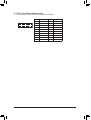
19) TPM (Trusted Platform Module Header)
YoumayconnectaTPM(TrustedPlatformModule)tothisheader.
Pin No. Denition Pin No. Denition
1 LCLK 11 LAD0
2GND 12 GND
3LFRAME 13 NC
4 No Pin 14 NC
5LRESET 15 SB3V
6 NC 16 SERIRQ
7LAD3 17 GND
8LAD2 18 NC
9VCC3 19 NC
10 LAD1 20 NC
- 20 -
La pagina si sta caricando...
La pagina si sta caricando...
La pagina si sta caricando...
La pagina si sta caricando...
La pagina si sta caricando...
La pagina si sta caricando...
La pagina si sta caricando...
La pagina si sta caricando...
La pagina si sta caricando...
La pagina si sta caricando...
La pagina si sta caricando...
La pagina si sta caricando...
La pagina si sta caricando...
La pagina si sta caricando...
La pagina si sta caricando...
La pagina si sta caricando...
La pagina si sta caricando...
La pagina si sta caricando...
La pagina si sta caricando...
La pagina si sta caricando...
La pagina si sta caricando...
La pagina si sta caricando...
La pagina si sta caricando...
La pagina si sta caricando...
-
 1
1
-
 2
2
-
 3
3
-
 4
4
-
 5
5
-
 6
6
-
 7
7
-
 8
8
-
 9
9
-
 10
10
-
 11
11
-
 12
12
-
 13
13
-
 14
14
-
 15
15
-
 16
16
-
 17
17
-
 18
18
-
 19
19
-
 20
20
-
 21
21
-
 22
22
-
 23
23
-
 24
24
-
 25
25
-
 26
26
-
 27
27
-
 28
28
-
 29
29
-
 30
30
-
 31
31
-
 32
32
-
 33
33
-
 34
34
-
 35
35
-
 36
36
-
 37
37
-
 38
38
-
 39
39
-
 40
40
-
 41
41
-
 42
42
-
 43
43
-
 44
44


Gigabyte B450 Gaming X Manuale del proprietario
- Tipo
- Manuale del proprietario
in altre lingue
Documenti correlati
-
Gigabyte B450 AORUS PRO WIFI Manuale del proprietario
-
-
-
-
-
-
-
-
-