
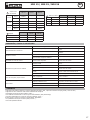
V4_10/03/2020
FR
2-5 / 32
MIG 15
MIG 25
MIG 36
DE
10-13 / 32
ES
14-17 / 32
RU
18-22 / 32
EN
6-9 / 32
NL
23-27 / 32
IT
28-31 / 32

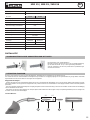
MIG 15 / MIG 25 / MIG 36
2
FR
AVERTISSEMENTS - RÈGLES DE SÉCURITÉ
CONSIGNE GÉNÉRALE
Ces instructions doivent être lues et bien comprises avant toute opération.
Toute modication ou maintenance non indiquée dans le manuel ne doit pas être entreprise.
Tout dommage corporel ou matériel dû à une utilisation non-conforme aux instructions de ce manuel ne pourra être retenu à la charge du fabricant.
En cas de problème ou d’incertitude, veuillez consulter une personne qualiée pour manier correctement l’installation.
PROTECTION INDIVIDUELLE ET DES AUTRES
Le soudage à l’arc peut être dangereux et causer des blessures graves voire mortelles.
Le soudage expose les individus à une source dangereuse de chaleur, de rayonnement lumineux de l’arc, de champs électromagnétiques (attention
au porteur de pacemaker), de risque d’électrocution, de bruit et d’émanations gazeuses.
Pour bien se protéger et protéger les autres, respecter les instructions de sécurité suivantes :
An de se protéger de brûlures et rayonnements, porter des vêtements sans revers, isolants, secs, ignifugés et en bon état, qui
couvrent l’ensemble du corps.
Utiliser des gants qui garantissent l’isolation électrique et thermique.
Utiliser une protection de soudage et/ou une cagoule de soudage d’un niveau de protection sufsant (variable selon les applica-
tions). Protéger les yeux lors des opérations de nettoyage. Les lentilles de contact sont particulièrement proscrites.
Il est parfois nécessaire de délimiter les zones par des rideaux ignifugés pour protéger la zone de soudage des rayons de l’arc, des
projections et des déchets incandescents.
Informer les personnes dans la zone de soudage de ne pas xer les rayons de l’arc ni les pièces en fusion et de porter les vêtements
adéquats pour se protéger.
Utiliser un casque contre le bruit si le procédé de soudage atteint un niveau de bruit supérieur à la limite autorisée (de même pour
toute personne étant dans la zone de soudage).
Tenir à distance des parties mobiles (ventilateur) les mains, cheveux, vêtements.
Ne jamais enlever les protections carter du générateur lorsque la source de courant de soudage est sous tension, le fabricant ne
pourrait être tenu pour responsable en cas d’accident.
Les pièces qui viennent d’être soudées sont chaudes et peuvent provoquer des brûlures lors de leur manipulation. Lors d’interven-
tion d’entretien sur la torche ou le porte-électrode, il faut s’assurer que celui-ci soit sufsamment froid en attendant au moins 10
minutes avant toute intervention. Le groupe froid doit être allumé lors de l’utilisation d’une torche refroidie eau an d’être sûr que
le liquide ne puisse pas causer de brûlures.
Il est important de sécuriser la zone de travail avant de la quitter an de protéger les personnes et les biens.
FUMÉES DE SOUDAGE ET GAZ
Les fumées, gaz et poussières émis par le soudage sont dangereux pour la santé. Il faut prévoir une ventilation sufsante et un
apport d’air est parfois nécessaire. Un masque à air frais peut être une solution en cas d’aération insufsante.
Vérier que l’aspiration est efcace en la contrôlant par rapport aux normes de sécurité.
Attention, le soudage en milieux connés nécessite une surveillance à distance de sécurité. Par ailleurs le soudage de certains matériaux contenant
du plomb, cadmium, zinc ou mercure voire du béryllium peuvent être particulièrement nocifs, dégraisser également les pièces avant de les souder.
Les bouteilles doivent être entreposées dans des locaux ouverts ou bien aérés. Elles doivent être en position verticale et maintenues à un support ou
sur un chariot. Le soudage doit être proscrit à proximité de graisse ou de peinture.
RISQUE DE FEU ET D’EXPLOSION
Protéger entièrement la zone de soudage, les matières inammables doivent être éloignées d’au moins 11 mètres.
Un équipement anti-feu doit être présent à proximité des opérations de soudage.
Attention aux projections de matières chaudes ou d’étincelles et même à travers des ssures, elles peuvent être source d’incendie ou d’explosion.
Éloigner les personnes, les objets inammables et les containers sous pressions à une distance de sécurité sufsante.
Le soudage dans des containers ou des tubes fermés est à proscrire et dans le cas où ils sont ouverts il faut les vider de toute matière inammable
ou explosive (huile, carburant, résidus de gaz …).
Les opérations de meulage ne doivent pas être dirigées vers la source de courant de soudage ou vers des matières inammables.

3
MIG 15 / MIG 25 / MIG 36
FR
SÉCURITÉ ÉLECTRIQUE
Une décharge électrique peut être une source d’accident grave direct ou indirect, voire mortel.
Ne jamais toucher les parties sous tension de la torche car celle-ci est branchée au circuit de soudage.
Ne pas toucher en même temps la torche et la pince de masse.
Toujours utiliser des vêtements secs et en bon état pour s’isoler du circuit de soudage. Portez des chaussures isolantes, quel que soit le milieu où
vous travaillez.
PRÉCAUTION D’EMPLOI
N’enroulez jamais la torche autour de votre corps.
Ne pas utiliser la torche pour déplacer la source de courant de soudage ou le dévidoir.
La torche doit être totalement déroulée an d’éviter toute surchauffe.
Arrêtez le générateur de courant après que la torche se soit refroidie, mais aussi avant chaque entretien et avant de remplacer ou contrôler les pièces
d’usure.
Contrôlez régulièrement l’état de la torche. Si celle-ci est endommagée, elle doit être remplacée.
DESCRIPTION GÉNÉRALE
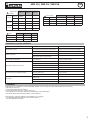
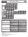
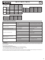
SPÉCIFICATIONS
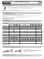
Les torches MIG15 / MIG25 / MIG 36 sont destinées au procédé de soudage MIG/MAG manuel.
DONNÉES TECHNIQUES
Composant
063754 063761
Composant
063778 063785 063792 063808
Référence 71846 71847 71848 71866 71879 C71453
Désignation MIG 15 MIG 25 MIG 36
Procédé MIG / MAG MIG / MAG MIG / MAG
Méthode de guidage Manuel Manuel Manuel
Courant assigné
Facteur de marche
correspondant
150 A
35%
180 A
60%
230 A
60%
340 A
60%
Tension assignée ≤113 V ≤113 V ≤113 V
Mode de refroidisse-
ment
Air Air Air
Connectique EURO EURO EURO
Gaz de protection
150 A CO2 /
120 A Mix
180 A CO2 /
150 A Mix
230 A CO2 /
200 A Mix
340 A CO2 /
300 A Mix
Débit de gaz 10-18 L/min 10-25 L/min 10-25 L/min 10-25 L/min
Tube Contact
Ø 0.8
Acier
Ø 1.0
Acier
Ø 0.8
Acier
Ø 0.8
Alu
Ø 1.2
Alu
Ø 0.8
Acier
Ø 1.0
Acier
Ø 1.0
Acier
Ø 1.0
Acier
Ø 1.0
Alu
Ø 1.2
Acier
Ø 1.2
Alu
Longueur de câble 3 m 3 m 3 m 3 m 4 m 4 m 3 m 4 m 3 m
Section de câble 14 mm² 16 mm² 25 mm² 42 mm²
Tension du switch
gâchette
10 V 10 V 10 V
Norme appliquée IEC 60974-7 IEC 60974-7 IEC 60974-7
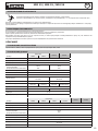
INSTALLATION
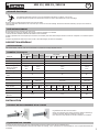
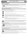
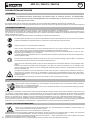
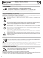
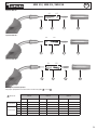
EXIGENCE DE RACCORDEMENT DE LA TORCHE
Le générateur doit être mis hors tension.
Insérer le connecteur de la torche (A) dans le logement femelle (E)
et visser la partie B. Attention à bien serrer la torche.
Pour retirer la torche, dévisser de la même manière que ci-dessus.
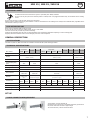
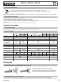
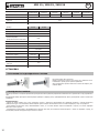
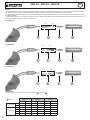
ÉQUIPEMENT DES TORCHES
La torche doit être équipée avec les bons consommables, choisis en fonction de la nature et diamètre de l.
Un mauvais choix de consommable provoquera des défauts de soudage, l’usure prématurée des consommables et voire un dysfonctionnement de
l’ensemble.

MIG 15 / MIG 25 / MIG 36
4
FR
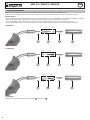
Projections :
- Lors du soudage, les projections peuvent facilement endommager la torche et le matériel de soudage. An d’éviter des contraintes sur le dévidage du
l, sur la stabilité de l’arc et de réduire l’effet d’isolation du gaz, les projections dans les embouts et les buses doivent être nettoyées dès que nécessaire.
- Les projections accumulées dans la buse qui n’ont pas été nettoyées en temps voulu provoqueront un court-circuit dans la torche, ce qui dégrade la
qualité du soudage.
- L’usage d’anti adhérent ou pâte anti adhérente réduit le collage des grattons/projections et facilite le nettoyage. An d’éviter de détériorer la torche,
ne pas utiliser un outil coupant pour enlever les projections.
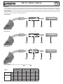
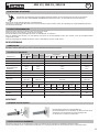
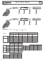
Torches MIG 15 :
1 2 3 4
A1 A2
Torche MIG 25 :
1 3 4
B1 B2
2
Torche MIG 36 :
1 3 4
D1 D2
2
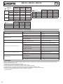
Consommables :
Vérier régulièrement l’état d’usure du tube contact
3
et de la buse
4
.
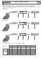
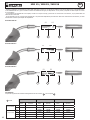
1
Gaine
MIG 15 MIG 25 MIG 36
Acier Alu Acier Alu Acier Alu
Ø 0.6/0.8 mm
3 m 041592 041578 - - - -
4 m 041837 044050 - - - -
Ø 1.0/1.2 mm
3 m - - 041608 041585 041608 041585
4 m - - 041844 044067 041844 044067
5 m - - 062276 - 062276 -
8 m - - - 038677 - 038677

5
MIG 15 / MIG 25 / MIG 36
FR
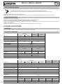
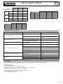
2
Support tube
contact
MIG 15 MIG 25 MIG 36
150 A
A1 x 5 042902 - -
A2 x 10 042988 - -
250 A
B1 x 5 - 042995 -
B2 x 5 - 042919 -
350 A
D1 x 3 - - 043008
D2 x 5 - - 042926
3
Tube contact
MIG 15 MIG 25 MIG 36
Ø 0.6 x 10 041905 - -
Ø 0.8 x 10 041912 - -
Ø 1.0 x 10 041929 041066 419803
Ø 1.2 x 10 041974 041073 419810
4
Buse
MIG 15 MIG 25 MIG 36
150 A 041875 - -
250 A - 041882
350 A - - 041783
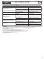
ANOMALIES, CAUSES, REMÈDES
SYMPTÔMES CAUSES POSSIBLES REMÈDES
Surchauffe de la torche
Le tube contact et son support ne sont pas serrés. Vérier et serrer le tube contact et son support.
Courant électrique de soudage excessif. Régler le courant électrique sur la machine à souder.
Gâchette inopérante
Le l de contrôle est coupé ou endommagé. Réparer le l
Le connecteur européen de la torche n’est pas cor-
rectement branché sur le poste à souder.
Vérier le branchement du connecteur de la torche.
Fil soudé dans le tube contact
Mauvais réglage.
Tube contact usé.
Vérier ou corriger le réglage.
Changer le tube de contact.
Alimentation irrégulière du l à souder
La pression des galets est trop faible ou trop élevée Régler la pression des galets (sur le moto dévidoir)
La gaine d’alimentation du l est bouchée. Nettoyer des deux extrémités
Tube contact incompatible avec le diamètre de l. Changer le tube contact
Galet du dévidoir de l usé ou mal monté. Changer le galet du dévidoir de l
Dysfonctionnement du système de dévidage du l. Vérier/réparer le dévidoir
Arc entre la buse et le composant à souder
Court-circuit entre le tube contact et la buse en
raison des éclaboussures.
Nettoyer la buse et pulvériser l’agent anti-éclabous-
sures à l’intérieur.
Isolateur du tube contact détérioré. Changer la buse.
Arc instable
Tube contact usé ou tube contact inadapté au
diamètre du l
Vérier et changer le tube contact.
Mauvais réglage du poste à souder. Corriger le réglage du poste à souder.
Gaine interne du l détériorée. Changer la gaine de l dans la torche.
GARANTIE
La garantie couvre tous défauts ou vices de fabrication pendant 2 ans, à compter de la date d’achat (pièces et main d’oeuvre).
La garantie ne couvre pas :
• Toutes autres avaries dues au transport.
• L’usure normale des pièces (Ex. : câbles, pinces, etc.).
• Les incidents dus à un mauvais usage (erreur d’alimentation, chute, démontage).
• Les pannes liées à l’environnement (pollution, rouille, poussière).
En cas de panne, retourner l’appareil à votre distributeur, en y joignant :
- un justicatif d’achat daté (ticket de sortie de caisse, facture….)
- une note explicative de la panne.

MIG 15 / MIG 25 / MIG 36
6
EN
WARNING - SAFETY RULES
GENERAL INSTRUCTIONS
Read and understand the following safety instructions before use.
Any modication or updates that are not specied in the instructions manual should not be underta-
ken.
The manufacturer is not liable for any injury or damage due to a non-compliance with the instructions featured in this manual.
If there is any issue or uncertainty, please consult a qualied person to handle the installation correctly.
INDIVIDUAL PROTECTION & OTHERS
Arc welding can be dangerous and can cause serious injury or even death.
Welding exposes the user to dangerous heat, arc rays, electromagnetic elds, risk of electric shock, noise and gas fumes. People wearing pacemakers
are advised to consult a doctor before using the welding machine.
To protect oneself as well as others, ensure the following safety precautions are taken:
In order to protect you from burns and radiations, wear clothing without turn-up or cuffs. These clothes must be insulating, dry,
reproof, in good condition and cover the whole body.
Wear protective gloves which guarantee electrical and thermal insulation.
Use sufcient welding protective gear for the whole body: hood, gloves, jacket, trousers... (varies depending on the application/
operation). Protect the eyes during cleaning operations. Contact lenses are prohibited during use.
It may be necessary to install reproof welding curtains to protect the area against arc rays, weld spatter and sparks.
Inform the people around the working area to never look at the arc nor the molten metal, and to wear protective clothes.
Ensure ear protection is worn by the operator if the work exceeds the authorised noise limit (the same applies to any person in
the welding area).
Keep hands, hair and clothes away from moving parts such as fans, and engines.
Never remove the safety covers from the cooling unit when the machine is plugged in. The manufacturer is not liable for any injury
or damage caused due to non-compliance with the safety precautions.
Parts that have just been welded will be hot and may cause burns when touched. During maintenance work on the torch or the
electrode holder, you should make sure it’s cold enough and wait at least 10 minutes before any intervention. When using a water-
cooled torch, make sure that the cooling unit is switched on to avoid any burns that could potentially be caused by the liquid.
It is important to secure the working area before leaving it to ensure protection of the goods and the safety of people.
WELDING FUMES AND GASES
The fumes, gas and dust generated by cutting are a potential health hazard. You must ensure adequate ventilation through
the installation of air supplies in order to extract fumes and gases. Using an air fed welding helmet is recommended in case of
insufcient ventilation in the workplace.
Check that the air supply is effective by referring to the recommended safety regulations.
Caution, welding in small spaces requires surveillance from a safe distance. Welding certain pieces of metal containing lead, cadmium, zinc, mercury
or beryllium can be extremely toxic. The user will also need to degrease the workpiece before welding.
Gas cylinders must be stored in an open or ventilated area. They must be stored vertically and held by a support or trolley to limit the risk of fall. Do
not weld in areas where grease or paint are stored.
FIRE AND EXPLOSION RISKS
Protect the entire welding area. Flammable materials must be moved to a minimum safe distance of 11 meters.
A re extinguisher must be readily available near the welding operations.
Be careful of weld spatter and sparks, even through cracks. If not careful then this could potentially lead to a re or an explosion.
Keep people, ammable materials/objects and containers that are under pressure at a safe distance.
Welding in closed containers or pipes should be avoided and , if they are opened, they must be emptied of any ammable or explosive material (oil,
fuel, gas ...).
Grinding operations should not be carried out close to the power supply or any ammable materials.

7
MIG 15 / MIG 25 / MIG 36
EN
ELECTRICAL SAFETY
An electric shock could cause serious injuries or potentially even deadly accidents.
Do not touch any live part of the machine (inside or outside) when it is plugged in because they are connected to the welding
circuit.
Do not touch the torch or and the earth clamp at the same time.
Always wear dry clothes which are in good condition in order to be isolated from the welding circuit. Always wear insulated shoes, regardless of the
environment in which you work in.
PRECAUTION FOR USE
Never wrap the welding leads around your body.
Do not use the torch to move the welding power source or wire feeder.
The torch must be fully uncoiled to prevent overheating.
Switch off the generator after the torch is cooled and before each maintenance and before replacing or control wearing parts.
Regularly check the condition of the torch. If damaged, the torch must be replaced.
GENERAL DESCRIPTION
SPECIFICATIONS
The MIG 15 / MIG 25 / MIG 36 torches are intended to the manual MIG / MAG welding processes.
TECHNICAL SPECIFICATIONS
Component
063754 063761
Component
063778 063785 063792 063808
Part number 71846 71847 71848 71866 71879 C71453
Designation MIG 15 MIG 25 MIG 36
Process
MIG / MAG
(GMAW / FCAW)
MIG / MAG
(GMAW / FCAW)
MIG / MAG
(GMAW / FCAW)
Guidance method Manual Manual Manual
Rated current
Corresponding duty
cycle
150 A
35%
180 A
60%
230 A
60%
340 A
60%
Rated voltage ≤113 V ≤113 V ≤113 V
Cooling mode Air Air Air
Connections EURO EURO EURO
Gas protection
150 A CO2 /
120 A Mix
180 A CO2 /
150 A Mix
230 A CO2 /
200 A Mix
340 A CO2 /
300 A Mix
Gas ow
10-18 L/min
(2.64/4.75 US
gpm)
10-25 L/min
(2.64/6.60 US gpm)
10-25 L/min
(2.64/6.60 US gpm)
10-25 L/min
(2.64/6.60 US gpm)
Contact tube
Ø 0.8
Steel
Ø 1.0
Steel
Ø 0.8
Steel
Ø 0.8
Alu
Ø 1.2
Alu
Ø 0.8
Steel
Ø 1.0
Steel
Ø 1.0
Steel
Ø 1.0
Steel
Ø 1.0
Alu
Ø 1.2
Steel
Ø 1.2
Alu
Cable length 3 m 3 m 3 m 3 m 4 m 4 m 3 m 4 m 3 m
Cross section 14 mm² 16 mm² 25 mm² 42 mm²
Switch trigger voltage 10 V 10 V 10 V
Applied standard IEC 60974-7 IEC 60974-7 IEC 60974-7
SET UP
TORCH CONNECTION REQUIREMENT
The generator must be switched off.
Insert the torch connector (A) in the female connector (E) and screw
the part B. Make sure the torch is tight enough.
To remove the torch, unscrew as shown below.

MIG 15 / MIG 25 / MIG 36
8
EN
TORCHES EQUIPMENT
The torch must be tted with the appropriate consumables, selected based on the application and selected current.
Using the wrong consumables will result in poor cutting, excessive use of consumables and possibly prevent the machine from working.
Welding Spatter :
- When welding, the spatter can easily damage the torch and welding equipment. To avoid constraints on the wire feeder, decrease arc stability or
reduce the gas isolation effect, spatter and other depots build-up in the nozzles must be cleaned as soon as necessary.
- Accumulated spatter in the nozzle will cause a short-circuit which could damage the torch over time if not cleaned in due course.
- The use of anti-splatter spray or paste is recommended. In order to avoid to damage to the torch, do not use a cutting tool to clean it.
Torch MIG 15 :
1 2 3 4
A1 A2
Torch MIG 25 :
1 3 4
B1 B2
2
Torche MIG 36 :
1 3 4
D1 D2
2
Consumables :
Regularly check the wear condition of the contact tube
3
and the nozzle
4
.

9
MIG 15 / MIG 25 / MIG 36
EN
1
Sheath
MIG 15 MIG 25
MIG 36
Steel Alu Steel Alu Steel Alu
Ø 0.6/0.8 mm
3 m 041592 041578 - - - -
4 m 041837 044050 - - - -
Ø 1.0/1.2 mm
3 m - - 041608 041585 041608 041585
4 m - - 041844 044067 041844 044067
5 m - - 062276 - 062276 -
8 m - - - 038677 - 038677
2
Contact tube
support
MIG 15 MIG 25 MIG 36
150 A
A1 x 5 042902 - -
A2 x 10 042988 - -
250 A
B1 x 5 - 042995 -
B2 x 5 - 042919 -
350 A
D1 x 3 - - 043008
D2 x 5 - - 042926
3
Contact tube
MIG 15 MIG 25 MIG 36
Ø 0.6 x 10 041905 - -
Ø 0.8 x 10 041912 -- -
Ø 1.0 x 10 041929 041066 419803
Ø 1.2 x 10 041974 041073 419810
4
Nozzle
MIG 15 MIG 25 MIG 36
150 A 041875 - -
250 A - 041882
350 A - - 041783
TROUBLESHOOTING, CAUSES, SOLUTIONS
SYMPTOMS POSSIBLE CAUSES SOLUTIONS
Torch overheating
The contact tube and its support are not tight
enough.
Check and tighten the contact tube and its support.
Excessive welding current. Adjust the current on the machine.
Inoperative trigger
The wire control is cutted or damaged. Repair the wire
The euro connector of the torch is not connected
correctly to the machine.
Check the connection of the torch.
Wire welded in contact tube
Incorrect settings
Contact tube used.
Check or correct the setting.
Change the contact tube.
Irregular wire feed
Roller pressure is too low or too high Change roller pressure (on the feed motor)
The feed sheathing is clogged. Clean both ends
Contact tip incompatible with the wire diameter. Change the contact tip.
The wire feeder roller is worn-out or incorrectly
tted.
Change the wire feeder roller.
Wire feed not working correctly. Check/repair the reel
Arc between the nozzle and the part to weld
Short circuit between the contact tip and the nozzle
due to spatter.
Clean the nozzle and spray anti-spatter agent inside.
Damaged isolator contact tip. Change the nozzle.
Unstable arc
Worn-out contact tip or inadequate contact tip with
the diameter of the wire.
Check and change the contact tip.
Incorrect setting of the welding machine. Correct the setting of the welding machine.
Internal sheath wire deteriorated. Change the wire liner in the torch.
WARRANTY
The warranty covers faulty workmanship for 2 years from the date of purchase (parts and labour).
The warranty does not cover:
• Transit damage.
• Normal wear of parts (eg. : cables, clamps, etc..).
• Damages due to misuse (power supply error, dropping of equipment, disassembling).
• Environment related failures (pollution, rust, dust).
In case of failure, return the unit to your distributor together with:
- The proof of purchase (receipt etc ...)
- A description of the fault reported

MIG 15 / MIG 25 / MIG 36
10
DE
SICHERHEITSANWEISUNGEN
ALLGEMEIN
Die Missachtung dieser Anweisungen und Hinweise kann zu schweren Personen- und Sachschäden
führen. Nehmen Sie keine Wartungarbeiten oder Veränderungen an dem Brenner vor, die nicht in der
Anleitung gennant werden.
Der Hersteller haftet nicht für Verletzungen oder Schäden, die durch unsachgemäße Handhabung dieses Brenners enstanden sind.
Bei Problemen oder Fragen zum korrekten Einsatz dieses Brenners, wenden Sie sich bitte an entsprechend qualiziertes und geschultes Fachpersonal
.
SICHERHEITSHINWEISE
Lichtbogenschweißen kann gefährlich sein und zu schweren - unter Umständen auch tödlichen - Verletzungen führen.
Beim Lichtbogen ist der Anwender einer Vielzahl potentieller Risiken ausgesetzt: gefährlicher Hitze, Lichtbogenstrahlung, elektromagnetische Störun-
gen (Personen mit Herzschnittmacher oder Hörgerät sollten sich vor Arbeiten in der Nähe der Maschinen von einem Arzt beraten lassen), elektrische
Schläge, Schweißlärm und -rauch.
Schützen Sie daher sich selbst und andere. Beachten Sie unbedingt die folgenden Sicherheitshinweise:
Die Strahlung des Lichtbogens kann zu schweren Augenschäden und Hautverbrennungen führen. Die Haut muss durch geeignete
trockene Schutzbekleidung (Schweißerhandschuhe, Lederschürze, Sicherheitsschuhe) geschützt werden.
Tragen Sie elektrisch- und wärmeisolierende Handschuhe.
Tragen Sie bitte Schweißschutzkleidung und einen Schweißschutzhelm mit einer genügen Schutzstufe (je nach Schweißart und
-strom). Schützen Sie Ihre Augen bei Reinigungsarbeiten. Kontaktlinsen sind ausdrücklich verboten!
Schirmen Sie den Schweißbereich bei entsprechenden Umgebungsbedingungen durch Schweißvorhänge ab, um Dritte vor Licht-
bogenstrahlung, Schweißspritzen, usw. zu schützen.
In der Nähe des Lichtbogens bendliche Personen müssen ebenfalls auf Gefahren hingewiesen werden und mit den nötigen Schutz-
mitteln ausgerüstet werden.
Bei Gebrauch des Schweißgerätes entsteht sehr großer Lärm, der auf Dauer das Gehör schädigt. Tragen Sie daher im Dauereinsatz
ausreichend Gehörschutz und schützen Sie in der Nähe arbeitende Personen.
Halten Sie mit den ungeschützten Händen, Haaren und losen Kleidungstücken ausreichenden Abstand zu sich bewegenden Teilen
(Lüfter).
Entfernen Sie unter keinen Umständen das Gerätegehäuse, wenn dieses am Stromnetz angeschlossen ist. Der Hersteller haftet
nicht für Verletzungen oder Schäden, die durch unsachgemäße Handhabung dieses Gerätes bzw. Nichteinhaltung der Sicherheit-
shinweise entstanden sind.
ACHTUNG! Das Werkstück ist nach dem Schweißen sehr heiß! Seien Sie daher im Umgang mit dem Werkstück vorsichtig, um
Verbrennungen zu vermeiden. Achten Sie vor Instandhaltung / Reinigung eines wassergekühlten Brenners darauf, dass Kühlag-
gregat nach Schweißende ca. 10 min weiterlaufen zu lassen, damit die Kühlüssigkeit entsprechend abkühlt und Verbrennungen
vermieden werden.
Der Arbeitsbereich muss zum Schutz von Personen und Geräten vor dem Verlassen gesichert werden.
SCHWEISSRAUCH/-GAS
Beim Schweißen entstehen Rauchgase bzw. toxische Dämpfen. Sorgen Sie daher immer für ausreichend Frischluft, technische
Belüftung oder ein zugelassenes Atemgerät.
Schweißen Sie nur in gut belüfteten Hallen, im Freien oder in geschlossenen Räumen mit ausreichend starker Absaugung, die den
aktuellen Sicherheitsstandards entspricht.
Achtung! Bei Schweißarbeiten in kleinen Räumen müssen Sicherheitsabstände besonders beachtet werden. Beim Schweißen von Blei, auch in Form
von Überzügen, verzinkten Teilen, Kadmium, «kadmierte Schrauben», Beryllium (meist als Legierungsbestandteil, z.B. Beryllium-Kupfer) und andere
Metalle entstehen giftige Dämpfe. Erhöhte Vorsicht gilt beim Schweißen von Behältern. Entleeren und reinigen Sie diese zuvor. Um die Bildung von
Giftgasen zu vermeiden bzw. zu verhindern, muss der Schweißbereich des Werkstückes von Lösungs- und Entfettungsmitteln gereinigt werden.
Die zum Schweißen benötigten Gasaschen müssen in gut belüfteter, gesicherter Umgebung aufbewahrt werden. Lagern Sie sie ausschließlich
stehend und sichern Sie sie z.B. mithilfe eines entsprechenden Fahrwagens gegen Umkippen. Informationen zum richtigen Umgang mit Gasaschen
erhalten Sie von Ihrem Gaslieferanten. Schweißarbeiten in unmittelbarer Nähe von Fetten und Farben sind grundsätzlich verboten!
BRAND- UND EXPLOSIONSGEFAHR
Sorgen Sie für ausreichenden Schutz des Schweißbereiches. Der Sicherheitsabstand für Gasaschen (brennbare Gase) und
andere brennbare Materialien beträgt mindestens 11 Meter.
Brandschutzausrüstung muss im Schweißbereich vorhanden sein.
Beachten Sie, dass die beim Schweißen entstehende heiße Schlacke, Spritzer und Funken eine potentielle Quelle für Bränder oder Explosionen
darstellen.Halten Sie einen Sicherheitsabstand zu Personen, entammbaren Gegenständen und Druckbehältern ein.
Schweißen Sie keine Behälter mit brennbare Materialien (auch keine Reste davon) -> Gefahr entammbarer Gase. Falls sie geöffnet sind, müssen
entammbare oder explosive Materialen entfernt werden.
Arbeiten Sie bei Schleifarbeiten immer in entgegengesetzter Richtung zu diesem Gerät und entammbaren Materialen.

11
MIG 15 / MIG 25 / MIG 36
DE
ELEKTRISCHE SICHERHEIT
Das Berühren stromführender Teile kann tödliche elektrische Schläge, schwere Verbrennungen bis zum Tod verursachen.
Berühren Sie daher UNTER KEINEN UMSTÄNDEN Teile des Brenners weil er am Schweißstromkreis angeschlossen ist.
Berühren Sie niemals gleichzeitig Brenner und Masseklemme!
Tragen Sie zur Isolierung beim Schweißen immer trockene Kleidung in gutem Zustand. Achten Sie unabhängig der Umgebungsbedingungen stets
auf isolierendes Schuhwerk.
VORSICHTSMASSNAHMEN
Achten Sie darauf, dass sich der Brenner nicht um Ihren Körper wickelt.
Ziehen Sie niemals an den Brenner, um das Gerät zu bewegen.
Das Brennerkabel muss komplett abgerollt werden um Überhitzerisiko zu verhindern.
Nach der Abkühlung des Brenners, vor jeder Wartung oder bevor Sie die Verschleißteile prüfen oder wechseln, muss die Schweißstromquelle
ausgeschaltet werden.
Prüfen Sie regelmäßig den Zustand des Brenners. Wenn er beschädigt ist, muss er ersetzt werden.
BESCHREIBUNG
ANWENDUNG
Die MIG15 / MIG25 / MIG 36 Brenner sind für manuelles MIG/MAG-Schweißverfahren geeignet.
TECHNISCHE ANGABEN
Komponente
063754 063761
Komponente
063778 063785 063792 063808
Artikelnummer 71846 71847 71848 71866 71879 C71453
Bezeichnung MIG 15 MIG 25 MIG 36
Verfahren MIG / MAG MIG / MAG MIG / MAG
Führungsmethode Manuell Manuell Manuell
Nennleistung
Entsprechende Ein-
schaltdauer
150 A
35%
180 A
60%
230 A
60%
340 A
60%
Nennspannung ≤113 V ≤113 V ≤113 V
Kühlungsart Luft Luft Luft
Anschlüsse EURO EURO EURO
Schutzgas
150 A CO2 /
120 A Mix
180 A CO2 /
150 A Mix
230 A CO2 /
200 A Mix
340 A CO2 /
300 A Mix
Gasdurchuss 10-18 L/min 10-25 L/min 10-25 L/min 10-25 L/min
Kontaktrohr
Ø 0.8
Stahl
Ø 1.0
Stahl
Ø 0.8
Stahl
Ø 0.8
Alu
Ø 1.2
Alu
Ø 0.8
Stahl
Ø 1.0
Stahl
Ø 1.0
Stahl
Ø 1.0
Stahl
Ø 1.0
Alu
Ø 1.2
Stahl
Ø 1.2
Alu
Kabellänge 3 m 3 m 3 m 3 m 4 m 4 m 3 m 4 m 3 m
Kabelquerschnitt 14 mm² 16 mm² 25 mm² 42 mm²
Spannung am Bren-
netaster
10 V 10 V 10 V
Geltende Norm IEC 60974-7 IEC 60974-7 IEC 60974-7
MONTAGE
BRENNER ANSCHLIESSEN
Die Schweißstromquelle muss ausgeschaltet sein.
Den Brenneranschluss (A) in die Buchse (E) stecken und den Teil B
anschrauben. Das Brennerkabel muss fest angezogen sein.
Um den Brenner zu entfernen, abschrauben.
AUSSTATTUNG DES BRENNERS
Der Brenner muss mit den für die Schweißung und den verwendeten Strom geeigneten Verschleißteile ausgerüstet werden.
Falsche Verschleißteile führen zu fehlerhaften Schweißungen, zum vorzeitigen Verschleiß der Verbrauchsteile oder zu Funktionsstörungen.r

MIG 15 / MIG 25 / MIG 36
12
DE
Spritzer:
- Während des Schweißvorgangs können Spritzer den Brenner und das Werkstückl beschädigen. Um Probleme beim Drahtvorschubs, der Lichtbogen-
stabilität und der Verringerung des Gasschutzes zu vermeiden, müssen Spritzer in den Düsen und Kappen entfernt werden.
- Spritzer in der Düse können einen Kurzschluss innerhalb des Brenners verursachen, wobei der Brenner beschädigt werden kann.
- Der Einsatz einer Antihaft-Paste oder -Spray verringert die Auswirkungen der Spritzer. Benutzen Sie keine Schneidwerkzeug, um die Spritzer zu
entfernen, da es den Brenner beschädigen könnte.
MIG 15 Brenner :
1 2 3 4
A1 A2
MIG 25 Brenner :
1 3 4
B1 B2
2
MIG 36 Brenner :
1 3 4
D1 D2
2
Verschleißteile:
Prüfen Sie regelmäßig den Verschleißzustand des Kontaktrohrs
3
und der Düse
4
.
1
Drahtseele
MIG 15 MIG 25 MIG 36
Stahldraht Aluminiumdraht Stahldraht Aluminiumdraht Stahldraht Aluminiumdraht
Ø 0.6/0.8 mm
3 m 041592 041578 - - - -
4 m 041837 044050 - - - -
Ø 1.0/1.2 mm
3 m - - 041608 041585 041608 041585
4 m - - 041844 044067 041844 044067
5 m - - 062276 - 062276 -
8 m - - - 038677 - 038677

13
MIG 15 / MIG 25 / MIG 36
DE
2
Halterung
kontaktr
MIG 15 MIG 25 MIG 36
150 A
A1 x 5 042902 - -
A2 x 10 042988 - -
250 A
B1 x 5 - 042995 -
B2 x 5 - 042919 -
350 A
D1 x 3 - - 043008
D2 x 5 - - 042926
3
Kontaktrohr
MIG 15 MIG 25 MIG 36
Ø 0.6 x 10 041905 -
Ø 0.8 x 10 041912 -
Ø 1.0 x 10 041929 041066 419803
Ø 1.2 x 10 041974 041073 419810
4
keramikdüse
MIG 15 MIG 25 MIG 36
150 A 041875 - -
250 A - 041882
350 A - - 041783
FEHLER, URSACHEN, LÖSUNGEN
SYMPTOME MÖGLICHE URSACHEN LÖSUNGEN
Überhitzung des Brenners
Der Kontaktrohr und seine Halterung sind nicht
festgezogen.
Kontaktrohr und Halterung prüfen und festziehen.
Zu hoher Schweißstrom. Den Schweißstrom am Gerät einstellen.
Fehlerhafte Brennertaste
Das Kontrolkabel ist durchtrennt oder beschädigt. Das Kabel reparieren
Der EURO-Anschluss des Brenners ist nicht richtig an
dem Gerät angeschlossen.
Prüfen Sie die Brenneranschlüsse.
Der Draht ist im Kontaktrohr festgeschweißt.
Fehlerhafte Einstellung.
Abgenutzes Kontaktrohr
Einstellung prüfen oder korrigieren.
Kontaktrohr wechseln.
Unregelmäßiger Schweißdrahtvorschub.
Der Druck der Drahführungsrollen ist zu niedrig oder
zu hoch.
Den Druck der Drahtführungsrollen einstellen (am
Drahtvorschub)
Die Drahtseele ist verstopft. Die beiden Enden reinigen.
Kontaktorohr ist nicht geeignet für den Drahtdurch-
messer.
Kontaktrohr wechseln.
Drahtführungsrolle ist abgenutzt oder falsch montiert. Drahtführungsrolle wechseln
Fehlfunktion des Drahtvorschubssystem. Den Drahtvorschubmotor prüfen oder reparieren
Lichtbogen zwischen der Düse und dem zu
schweißenden Element
Kurzschluss zwischen Kontaktrohr und Düse durch
Spritzer.
Die Düse reinigen und Antihaft-Spray in die Düse
sprühen.
Beschädigter Isolator des Kontaktrohrs Düse wechseln.
Instabiler Lichtbogen
Abgenutzes Kontaktrohr oder für den Drahtdurch-
messer nicht geeignet.
Prüfen und Kontaktrohr wechseln.
Fehlerhafte Einstellung des Geräts. Einstellung am Gerät korrigieren.
Beschädigte interne Drahtführungseele Die Drahtführungsseele im Brenner wechseln.
GARANTIE
Die Garantieleistung des Herstellers erfolgt ausschließlich bei Fabrikations- oder Materialfehlern, die binnen 24 Monate nach Kauf angezeigt werden
(Nachweis Kaufbeleg).
Die Garantieleistung erfolgt nicht bei:
• Durch Transport verursachten Beschädigungen.
• Normalem Verschleiß der Teile (z.B. : Kabel, Klemmen, usw.) sowie Gebrauchsspuren.
• Von unsachgemäßem Gebrauch verursachten Defekten (Sturz, harte Stöße, Demontage).
• Durch Umwelteinüsse entstandene Defekte (Verschmutzung, Rost, Staub).
Die Reparatur erfolgt erst nach Erhalt einer schriftlichen Akzeptanz (Unterschrift) des zuvor vorgelegten Kostenvoranschlages durch den Besteller. Im
Fall einer Garantieleistung trägt GYS ausschließlich die Kosten für den Rückversand an den Fachhändler.

MIG 15 / MIG 25 / MIG 36
14
ES
ADVERTENCIAS - NORMAS DE SEGURIDAD
CONSIGNA GENERAL
Estas instrucciones se deben leer y comprender antes de toda operación.
Toda modicación o mantenimiento no indicado en el manual no se debe llevar a cabo.
Todo daño físico o material debido a un uso no conforme con las instrucciones de este manual no podrá atribuírsele al fabricante.
En caso de problema o de incertidumbre, consulte con una persona cualicada para manejar correctamente el aparato.
PROTECCIÓN INDIVIDUAL Y DE LOS OTROS
La soldadura al arco puede ser peligrosa y causar lesiones graves e incluso mortales.
La soldadura expone a los individuos a una fuente peligrosa de calor, de radiación lumínica del arco, de campos electromagnéticos (atención a los que
lleven marcapasos), de riesgo de electrocución, de ruido y de emisiones gaseosas.
Para protegerse correctamente y proteger a los demás, siga las instrucciones de seguridad siguientes:
Para protegerse de quemaduras y de radiaciones, lleve ropas sin solapas, aislantes, secos, ignífugos y en buen estado que cubran
todo el cuerpo.
Utilice guantes que aseguren el aislamiento eléctrico y térmico.
Utilice una protección de soldadura y/o una capucha de soldadura de un nivel de protección suciente (variable según aplicaciones).
Protéjase los ojos durante operaciones de limpieza. Las lentillas de contacto están particularmente prohibidas.
A veces es necesario delimitar las zonas mediante cortinas ignífugas para proteger la zona de soldadura de los rayos del arco,
proyecciones y de residuos incandescentes.
Informe a las personas en la zona de soldadura de que no miren los rayos del arco ni las piezas en fusión y que lleven ropas ade-
cuadas para protegerse.
Utilice un casco contra el ruido si el proceso de soldadura alcanza un nivel de ruido superior al límite autorizado (así como cualquier
otra persona que estuviera en la zona de soldadura).
Las manos, el cabello y la ropa deben estar a distancia de las partes móviles (ventilador).
No quite nunca el cárter del grupo de refrigeración del aparato estando bajo tensión, el fabricante no podrá ser considerado res-
ponsable en caso de accidente.
Las piezas soldadas están caliente y pueden provocar quemaduras durante su manipulación. Cuando se hace un mantenimiento de
la antorcha o portaelectrodos, se debe asegurar que esta esté lo sucientemente fría y espere al menos 10 minutos antes de toda
intervención. El grupo de refrigeración se debe encender cuando se utilice una antorcha refrigerada por líquido para que el líquido
no pueda causar quemaduras.
Es importante asegurar la zona de trabajo antes de dejarla para proteger las personas y los bienes materiales.
HUMOS DE SOLDADURA Y GAS
El humo, el gas y el polvo que se emite durante el corte son peligrosos para la salud. Hay que prever una ventilación suciente y
en ocasiones puede ser necesario un aporte de aire. Una máscara de aire puede ser una solución en caso de aireación insuciente.
Compruebe que la aspiración es ecaz controlándola conforme a las normas de seguridad.
Atención, la soldadura en los lugares de pequeñas dimensiones requiere una vigilancia a distancia de seguridad. La soldadura de algunos materiales
que contengan plomo, cadmio, zinc, mercurio o berilio pueden ser particularmente nocivos. Desengrase las piezas antes de soldarlas.
Las botellas se deben colocar en locales abiertos o bien aireados. Se deben colocar en posición vertical y sujetadas con un soporte o sobre un carro.
La soldadura no se debe efectuar cerca de grasa o de pintura.
RIESGO DE FUEGO Y DE EXPLOSIÓN
Proteja completamente la zona de soldadura, los materiales inamables deben alejarse al menos 11 metros.
Cerca de la zona de operaciones de soldadura debe haber un anti-incendios.
Atención a las proyecciones de materiales calientes o chispas incluso a través de las suras. Pueden generar un incendio o una explosión.
Aleje las personas, objetos inamables y contenedores a presión a una distancia de seguridad suciente.
La soldadura en contenedores o tubos cerrados está prohibida y en caso de que estén abiertos se les debe vaciar de cualquier material inamable o
explosivo (aceite, carburante, residuos de gas...).
Las operaciones de pulido no se deben dirigir hacia la fuente de energía de soldadura o hacia materiales inamables.

15
MIG 15 / MIG 25 / MIG 36
ES
SEGURIDAD ELÉCTRICA
Una descarga eléctrica puede ser una fuente de accidente grave directo o indirecto, incluso mortal.
No toque nunca las partes bajo tensión de la antorcha ya que están conectadas al circuito de soldadura al arco.
No toque al mismo tiempo la antorcha y la pinza de masa.
Utilizar siempre ropas secas y en buen estado para aislarse del circuito de soldadura. Lleve zapatos aislantes, sin importar el lugar donde trabaje.
PRECAUCIÓN DE EMPLEO
No enrolle cables de la antorcha alrededor de su cuerpo.
No utilice la antorcha para desplazar el generador de soldadura o la devanadera.
La antorcha debe estar completamente desenrollados para evitar cualquier sobrecalentamiento.
Detenga el generador de corriente una vez que la antorcha se haya enfriado y antes de cada mantenimiento, cambio o control de las piezas de
recambio.
Controle regularmente el estado de la antorcha. Si esta está dañada, se debe reemplazar.
DESCRIPCIÓN GENERAL
ESPECIFICACIONES
Las antorchas MIG15 / MIG25 / MIG 36 están destinadas al proceso de corte MIG / MAG manual.
DATOS TÉCNICOS
Componente
063754 063761
Componente
063778 063785 063792 063808
Referencia 71846 71847 71848 71866 71879 C71453
Designación MIG 15 MIG 25 MIG 36
Proceso MIG / MAG MIG / MAG MIG / MAG
Método de guiado Manual Manual Manual
Corriente asignada
Ciclo de trabajo cor-
respondiente
150 A
35%
180 A
60%
230 A
60%
340 A
60%
Tensión asignada ≤113 V ≤113 V ≤113 V
Modo de refrigeración Aire Aire Aire
Conectores EURO EURO EURO
Gas de protección
150 A CO2 /
120 A Mix
180 A CO2 /
150 A Mix
230 A CO2 /
200 A Mix
340 A CO2 /
300 A Mix
Caudal de gas 10-18 L/min 10-25 L/min 10-25 L/min 10-25 L/min
Tubo de contacto
Ø 0.8
Acero
Ø 1.0
Acero
Ø 0.8
Acero
Ø 0.8
Aluminio
Ø 1.2
Aluminio
Ø 0.8
Acero
Ø 1.0
Acero
Ø 1.0
Acero
Ø 1.0
Acero
Ø 1.0
Aluminio
Ø 1.2
Acero
Ø 1.2
Aluminio
Longitud de cable 3 m 3 m 3 m 3 m 4 m 4 m 3 m 4 m 3 m
Sección de cable 14 mm² 16 mm² 25 mm² 42 mm²
Tensión del interruptor
gatillo
10 V 10 V 10 V
Norma aplicada IEC 60974-7 IEC 60974-7 IEC 60974-7
INSTALACIÓN
EXIGENCIAS PARA LA CONEXIÓN DE LA ANTORCHA
El generador no debe estar conectado a la red eléctrica.
Inserte el conector de la antorcha (A) en el receptor hembra (E) y
atornille la parte B. Asegúrese que la antorcha quede bien jada.
Para retirar la antorcha, desatornille del mismo modo que antes.
EQUIPAMIENTO DE LAS ANTORCHAS
La antorcha debe estar equipada con los consumibles correctos, seleccionados en función de la aplicación y de la corriente ajustada.
Una mala selección de consumibles provocará fallos de corte, el desgaste prematuro de los consumibles e incluso un mal funcionamiento del conjunto.
Salpicaduras:

MIG 15 / MIG 25 / MIG 36
16
ES
- Durante la soldadura, las salpicaduras pueden dañar fácilmente la antorcha y el material de soldadura. Para evitar obstáculos en el devanado de hilo,
en la estabilidad del arco y que se reduzca el efecto del aislamiento del gas, las salpicaduras en las puntas y boquillas se deben limpiar en cuanto
se vea necesario.
. La acumulación de salpicaduras en la boquilla, cuando no se limpia a tiempo, provocarán un cortocircuito en la antorcha, lo que podría dañar los
elementos de la antorcha.
- Se recomienda el uso de un agente anti-salpicaduras o una pasta anti-salpicaduras para reducirlas. Para evitar el deterioro de la antorcha, no utilice
herramientas cortantes para limpiar las salpicaduras.
Antorchas MIG 15 :
1 2 3 4
A1 A2
Antorcha MIG 25 :
1 3 4
B1 B2
2
Antorcha MIG 36 :
1 3 4
D1 D2
2
Consumibles:
Compruebe regularmente el estado de desgaste del tubo de contacto
3
y de la boquilla
4
.
1
Funda
MIG 15 MIG 25 MIG 36
Acero Aluminio Acero Aluminio Acero Aluminio
Ø 0.6/0.8 mm
3 m 041592 041578 - - - -
4 m 041837 044050 - - - -
Ø 1.0/1.2 mm
3 m - - 041608 041585 041608 041585
4 m - - 041844 044067 041844 044067
5 m - - 062276 - 062276 -
8 m - - - 038677 - 038677

17
MIG 15 / MIG 25 / MIG 36
ES
2
Soporte tubo
de contacto
MIG 15 MIG 25 MIG 36
150 A
A1 x 5 042902 - -
A2 x 10 042988 - -
250 A
B1 x 5 - 042995 -
B2 x 5 - 042919 -
350 A
D1 x 3 - - 043008
D2 x 5 - - 042926
3
Tubo de contacto
MIG 15 MIG 25 MIG 36
Ø 0.6 x 10 041905 - -
Ø 0.8 x 10 041912 - -
Ø 1.0 x 10 041929 041066 419803
Ø 1.2 x 10 041974 041073 419810
4
Boquilla
MIG 15
MIG 25 MIG 36
150 A 041875 - -
250 A - 041882
350 A - - 041783
ANOMALÍAS, CAUSAS Y SOLUCIONES
Anomaías Causas posibles Soluciones
Sobrecalentamiento de la antorcha
El tubo de contacto y su soporte no están apretados.
Compruebe y apriete el tubo de contacto y su
soporte.
Corriente eléctrica de soldadura excesiva.
Ajuste la corriente eléctrica sobre el equipo de
soldadura.
El gatillo no funciona
El cable de control está cortado o dañado. Repare el cable
El conector europeo de la antorcha no está correcta-
mente conectado al equipo de soldadura.
Compruebe la conexión del conector de la antorcha.
Hilo soldado en el tubo de contacto
Mal ajuste.
Tubo de contacto desgastado.
Compruebe o corrija el ajuste.
Cambie el tubo de contacto.
Alimentación irregular del hilo de soldadura
La presión de los rodillos es demasiado débil o
demasiado elevada
Ajuste la presión de los rodillos (sobre la motodeva-
nadera)
La funda de alimentación de hilo está obstruida. Limpie las dos extremidades
Tubo de contacto incompatible con el diámetro de
hilo.
Cambie el tubo de contacto
Rodillo de devanadera de hilo desgastado o mal
montado.
Cambie el rodillo de la devanadera de hilo
Mal funcionamiento del sistema de devanado de hilo. Compruebe/repare la devanadera
Arco entre la boquilla y la pieza a soldar
Cortocircuito entre el tubo de contacto y la boquilla
debido a salpicaduras.
Limpie la boquilla y pulverice un agente anti-salpica-
duras en el interior.
Aislador del tubo de contacto deteriorado. Cambie la boquilla.
Arco inestable
Tubo de contacto desgastado o tubo de contacto
inadaptado al diámetro de hilo.
Compruebe y cambie el tubo de contacto.
Mal ajuste del equipo de soldadura. Corrija el ajuste de equipo de soldadura.
Funda interna del hilo deteriorado. Cambie la funda de hilo en la antorcha.
GARANTÍA
La garantía cubre todos los defectos o vicios de fabricación durante 2 años, a partir de la fecha de compra (piezas y mano de obra)
La garantía no cubre: Todas las otras averías resultando del transporte
• El desgaste normal de las piezas (cables, pinzas…)
• Los incidentes resultando de un mal uso (error de alimentación, caída, desmontaje)
• Los fallos relacionados con el entorno (polución, oxidación, polvo…)
En caso de fallo, regresen la maquina a su distribuidor, adjuntando:
• Un justicativo de compra con fecha (recibo, factura…)
• Una nota explicativa del fallo.

MIG 15 / MIG 25 / MIG 36
18
RU
ПРЕДОСТЕРЕЖЕНИЯ - ПРАВИЛА БЕЗОПАСНОСТИ
ОБЩИЕ УКАЗАНИЯ
Эти указания должны быть прочтены и поняты до начала сварочных работ.
Изменения и ремонт, не указанные в этой инструкции, не должны быть предприняты.
Производитель не несет ответственности за травмы и материальные повреждения связанные с несоответствующим данной инструкции
использованием аппарата. В случае проблемы или сомнений, обратитесь к квалифицированному профессионалу для правильного
подключения.
ИНДИВИДУАЛЬНАЯ ЗАЩИТА И ЗАЩИТА ОКРУЖАЮЩИХ
Дуговая сварка может быть опасной и вызвать тяжелые и даже смертельные ранения.
Сварочные работы подвергают пользователя воздействию опасного источника тепла, светового излучения дуги, электромагнитных полей
(особое внимание лицам, имеющим электрокардиостимулятор), сильному шуму, выделениям газа, а также могут стать причиной поражения
электрическим током. Что бы правильно защитить себя и защитить окружающих, соблюдайте следующие правила безопасности:
Чтобы защитить себя от ожогов и облучения при работе с аппаратом, надевайте сухую рабочую защитную одежду (в
хорошем состоянии) из огнеупорной ткани, без отворотов, которая покрывает полностью все тело.
Работайте в защитных рукавицах, обеспечивающие электро- и термоизоляцию.
Используйте средства защиты для сварки и/или шлем для сварки соответствующего уровня защиты (в зависимости от
использования). Защитите глаза при операциях очистки. Ношение контактных линз воспрещается.
В некоторых случаях необходимо окружить зону огнеупорными шторами, чтобы защитить зону сварки от лучей, брызг
и накаленного шлака. Предупредите окружающих не смотреть на дугу и обрабатываемые детали и надевать защитную
рабочую одежду.
Носите наушники против шума, если сварочный процесс достигает звукового уровня выше дозволенного (это же относится
ко всем лицам, находящимся в зоне сварки).
Держите руки, волосы, одежду подальше от подвижных частей (двигатель, вентилятор…).
Никогда не снимайте защитный корпус с системы охлаждения, когда источник под напряжением. Производитель не несет
ответственности в случае несчастного случая.
Только что сваренные детали горячи и могут вызвать ожоги при контакте с ними. Во время техобслуживания горелки или
электрододержателя убедитесь, что они достаточно охладились и подождите как минимум 10 минут перед началом работ. При
использовании горелки с жидкостным охлаждением система охлаждения должна быть включена, чтобы не обжечься жидкостью.
Очень важно обезопасить рабочую зону перед тем, как ее покинуть, чтобы защитить людей и имущество.
СВАРОЧНЫЕ ДЫМ И ГАЗ
Выделяемые при резке дым, газ и пыль опасны для здоровья. Вентиляция должна быть достаточной, и может
потребоваться дополнительная подача воздуха.
При недостаточной вентиляции можно воспользоваться маской сварщика-респиратором.
Проверьте, чтобы всасывание воздуха было эффективным в соответствии с нормами безопасности.
Будьте внимательны: сварка в небольших помещениях требует наблюдения на безопасном расстоянии. Кроме того, сварка некоторых
металлов, содержащих свинец, кадмий, цинк, ртуть или даже бериллий, может быть чрезвычайно вредной. Следует очистить от жира детали
перед сваркой.
Газовые баллоны должны храниться в открытых или хорошо проветриваемых помещениях. Они должны быть в вертикальном положении и
закреплены на стойке или тележке. Ни в коем случае не варить вблизи жира или краски.
РИСК ПОЖАРА И ВЗРЫВА
Полностью защитите зону сварки. Возгораемые материалы должны быть удалены как минимум на 11 метров.
Противопожарное оборудование должно находиться вблизи проведения сварочных работ.
Осторожно с брызгами горячего материала или искр, даже через щели. Они могут повлечь за собой пожар или взрыв.
Удалите людей, возгораемые предметы и все емкости под давлением на безопасное расстояние.
Ни в коем случае не варите в контейнерах или закрытых трубах. В случае, если они открыты, то перед сваркой их нужно освободить от всех
взрывчатых или возгораемых веществ (масло, топливо, остаточные газы …).
Во время операции шлифования не направляйте инструмент в сторону источника сварочного тока или возгораемых материалов.

19
MIG 15 / MIG 25 / MIG 36
RU
ЭЛЕКТРИЧЕСКАЯ БЕЗОПАСНОСТЬ
Электрический разряд может вызвать прямые или косвенные ранения, и даже смерть.
Никогда не дотрагивайтесь до частей горелки, находящихся под напряжением, т.к. она подключена к сварочной цепи.
Никогда не дотрагивайтесь одновременно до горелки и до зажима массы.
Всегда носите сухую одежду в хорошем состоянии для изоляции от сварочной цепи. Носите изолирующую обувь независимо от той среды,
где вы работаете.
МЕРЫ ПРЕДОСТОРОЖНОСТИ
Ни в коем случае не оборачивайте вокруг себя рукав горелки.
Не пользуйтесь горелкой для переноса источника сварочного тока или подающего устройства.
Рукав горелки должен быть полностью размотан во избежании перегрева.
Выключайте источник тока после того, как горелка остынет, а также перед каждым техобслуживанием и перед тем, как заменить или
проверить быстроизнашивающиеся детали.
Регулярно проверяйте состояние горелки. В случае повреждения она должна быть заменена.
ОПИСАНИЕ
ТЕХНИЧЕСКИЕ ХАРАКТЕРИСТИКИ
Горелки MIG15 / MIG25 / MIG 36 предназначены для ручных методов сварки MIG / MAG.
ТЕХНИЧЕСКИЕ ДАННЫЕ
Компонент
063754 063761
Артикул 71846 71847
Наименование MIG 15
Метод сварки МИГ/МАГ
Метод направления Ручной режим
Номинальный ток
Соответствующая
продолжительность включения
150 A
35%
180 A
60%
Номинальное напряжение ≤113 V
Режим охлаждения Воздух
Подключение ЕВРО
Защитный газ
150 A CO2 /
120 A Mix
180 A CO2 /
150 A Mix
Расход газа 10-18 л/мин 10-25 л/мин
Контактная трубка
Ø 0.8
стальную
Ø 1.0
стальную
Ø 0.8
стальную
Ø 0.8
алюминиевую
Длина кабеля 3 м
Сечение кабеля 14 мм² 16 мм²
Напряжение переключателя
триггера
10 B
Действующие нормы IEC 60974-7
Компонент
063778 063785
Артикул 71848 71866 71879 C71453
Наименование MIG 25
Метод сварки МИГ/МАГ
Метод направления Ручной режим
Номинальный ток
Соответствующая
продолжительность включения
230 A
60%
Номинальное напряжение ≤113 V
Режим охлаждения Воздух
Подключение ЕВРО
Защитный газ
230 A CO2 /
200 A Mix
Расход газа 10-25 л/мин

MIG 15 / MIG 25 / MIG 36
20
RU
Контактная трубка
Ø 1.2
алюминиевую
Ø 0.8
стальную
Ø 1.0
стальную
Ø 1.0
стальную
Ø 1.0
стальную
Ø 1.0
алюминиевую
Длина кабеля 3 м 3 м 3 м 4 м 4 м 3 м
Сечение кабеля 25 мм²
Напряжение переключателя
триггера
10 B
Действующие нормы IEC 60974-7
Артикул 063792 063808
Наименование MIG 36
Метод сварки МИГ/МАГ
Метод направления Ручной режим
Номинальный ток
Соответствующая
продолжительность включения
340 A
60%
Номинальное напряжение ≤113 V
Режим охлаждения Воздух
Подключение ЕВРО
Защитный газ
340 A CO2 /
300 A Mix
Расход газа 10-25 л/мин
Контактная трубка
Ø 1.2
стальную
Ø 1.2
алюминиевую
Длина кабеля 4 м 3 м
Сечение кабеля 42 мм²
Напряжение переключателя
триггера
10 B
Действующие нормы IEC 60974-7
УСТАНОВКА
ТРЕБОВАНИЯ ПО ПОДСОЕДИНЕНИЮ ГОРЕЛКИ
Источник должен быть отключен.
Вставьте коннектор горелки (A) в гнездо (E) и завинтите часть
B. Внимание: горелку нужно крепко привинтить.
Для отсоединения горелки отвинтите ее таким же образом, как
описано выше.
ОБОРУДОВАНИЕ ГОРЕЛОК
Горелка должна быть оснащена правильными расходными комплектующими, выбранными в зависимости от применения и отрегулированного
тока.
Неправильный выбор расходных комплектующих приведет к дефекту резки, преждевременному износу расходников и даже к сбою всего
устройства.
Разбрызгивание :
- Брызги во время сварки могут легко повредить горелку и сварочное оборудование. Во избежание проблем с подачей проволоки,
стабильностью дуги и со снижением газовой защиты нужно очищать наконечники и сопла от шлака каждый раз, когда это требуется.
- Если вовремя не вычистить шлак, накапливаемый в сопле, то он может вызвать короткое замыкание в горелке, что может повредить
различные части горелки.
- Рекомендуется использовать противобрызговое средство или мазь для снижения количества брызг. Чтобы не повредить горелку, не
используйте режущих инструментов для очистки от шлака.
La pagina si sta caricando...
La pagina si sta caricando...
La pagina si sta caricando...
La pagina si sta caricando...
La pagina si sta caricando...
La pagina si sta caricando...
La pagina si sta caricando...
La pagina si sta caricando...
La pagina si sta caricando...
La pagina si sta caricando...
La pagina si sta caricando...
La pagina si sta caricando...
-
 1
1
-
 2
2
-
 3
3
-
 4
4
-
 5
5
-
 6
6
-
 7
7
-
 8
8
-
 9
9
-
 10
10
-
 11
11
-
 12
12
-
 13
13
-
 14
14
-
 15
15
-
 16
16
-
 17
17
-
 18
18
-
 19
19
-
 20
20
-
 21
21
-
 22
22
-
 23
23
-
 24
24
-
 25
25
-
 26
26
-
 27
27
-
 28
28
-
 29
29
-
 30
30
-
 31
31
-
 32
32


GYS MIG torch 250A - 4m Manuale del proprietario
- Tipo
- Manuale del proprietario
- Questo manuale è adatto anche per
in altre lingue
Documenti correlati
-
GYS MIG torch 150A - 3m Manuale del proprietario
-
-
-
-
GYS PROMIG 400 G DV Manuale utente
-
GYS TRIMIG 300-4S Manuale del proprietario
-
GYS SMARTMIG 142 Manuale del proprietario
-
-
GYS WIRE FEEDER AIR/WATER NEOFEED-4W Manuale del proprietario
-