La pagina si sta caricando...

IT
EN
RICEVITORE RADIO UNIVERSALE
OPERANTE SU 868 MHz
Manuale di installazione, uso e manutenzione
Installation, operation and maintenance manual
UNIVERSAL RADIO RECEIVER
OPERATING ON 868 MHz
ART. / ITEM:
4052GR868RX8
RICEVITORE
RADIO OPERANTE SU
868 MHz
UNIVERSAL RADIO
RECEIVER OPERATING
ON 868 MHz
MADE IN ITALY
La dichiarazione CE del presente articolo
è reperibile sul sito www.lince.net.
The CE declaration of this item is available
on www.lince.net website.

2
LINCE ITALIA S.p.A.
- Istruzioni originali -
1. INTRODUZIONE ................................................................................................ 3
1.1 CARATTERISTICHE GENERALI ........................................................... 3
1.2 CARATTERISTICHE TECNICHE ........................................................... 3
1.3 CONTENUTO DELLA CONFEZIONE .................................................... 3
1.4 IDENTIFICAZIONE DELLE PARTI ......................................................... 4
2. INSTALLAZIONE............................................................................................... 5
2.1 MONTAGGIO A MURO ...................................................................................... 5
2.2 MONTAGGIO IN CENTRALE ................................................................. 5
2.3 COLLEGAMENTI ELETTRICI ................................................................ 5
2.4 IMPOSTAZIONI ...................................................................................... 5
3. MEMORIZZAZIONE ......................................................................................... 6
4. TEST PORTATA RADIO .................................................................................... 6
5. ANTISATURAZIONE ........................................................................................ 7
6. SUPERVISIONE ................................................................................................7
7. BATTERIA BASSA ............................................................................................ 7
8. CANCELLAZIONE ............................................................................................ 7
8.1 CANCELLAZIONE SELETTIVA ..............................................................7
8.2 CANCELLAZIONE TOTALE ................................................................... 8
9. MANUTENZIONE E VERIFICHE PERIODICHE ............................................... 8
10. SMALTIMENTO E ROTTAMAZIONE ................................................................ 8
INDICE
- Translation of the original instructions (original instructions in Italian) -
Le informazioni riportate in questo manuale sono state compilate
con cura, tuttavia LINCE ITALIA S.p.A. non può essere ritenuta
responsabile per eventuali errori e/o omissioni. LINCE ITALIA
S.p.A. si riserva il diritto di apportare in ogni momento e senza
preavviso, miglioramenti e/o modiche ai prodotti descritti
nel presente manuale. Consultare il sito www.lince.net per le
condizioni di assistenza e garanzia. LINCE ITALIA S.p.A. pone
particolare attenzione al rispetto dell’ambiente. Tutti i prodotti ed i
processi produttivi sono progettati con criteri di eco-compatibilità.
Il presente articolo è stato prodotto in Italia.
The information in this manual has been issued with care, but
LINCE ITALIA S.p.A. will not be responsible for any errors or
omissions. LINCE ITALIA S.p.A. reserves the right to improve
or modify the products described in this manual at any time
and without advance notice. Terms and conditions regarding
assistance and the product warranty can be found at LINCE
ITALIA’s website www.lince.net. LINCE ITALIA S.p.A. makes it a
priority to respect the environment. All products and production
processes are designed to be eco-friendly and sustainable.
This product has been Made in Italy
1. DESCRIPTION .................................................................................................. 3
1.1 GENERAL FEATURES .......................................................................... 3
1.2 TECHNICAL FEATURES ....................................................................... 3
1.3 PACKAGING CONTENTS ...................................................................... 3
1.4 PARTS IDENTIFICATION.......................................................................4
2. INSTALLATION ................................................................................................. 4
2.1 WALL MOUNTING .................................................................................4
2.2 CONTROL PANEL MOUNTING ............................................................. 4
2.2 ELECTRICAL WIRING ........................................................................... 5
2.4 SETTINGS ............................................................................................. 5
3. STORING ...........................................................................................................6
4. RADIO RANGE TEST ...................................................................................... 6
5. ANTISATURATION ............................................................................................ 7
6. SUPERVISION................................................................................................... 7
7. LOW BATTERY .................................................................................................7
8. ERASING ........................................................................................................... 7
8.1 SELECTIVE ERASING ...................................................................................... 7
8.2 TOTAL ERASING ...................................................................................8
9. MAINTENANCE AND PERIODIC CHECKS ..................................................... 8
10. DISPOSAL AND SCRAPPING .......................................................................... 8
CONTENTS

3
LINCE ITALIA S.p.A.
1.2 CARATTERISTICHE TECNICHE
4052GR868RX8
Alimentazione 10÷15 Vcc
Assoribmento 40mA @ 12 Vcc con tamper chiuso
Frequenza di sercizio 868 MHZ
Ingressi 8 ingressi radio
LED di segnalazione 11
Uscite programmibili 8 uscite cablate; 1 uscita 24H; 1 uscita stato
bassa
Temperatura di esercizio 5 ÷ 40 °C
Dimensioni (mm) 170 x 107 x 30
1. INTRODUZIONE
Il ricevitore 4052GR868RX8 è una interfaccia che permette di
trasferire 8 canali radio su altrettanti ingressi di una centrale
lare. Oltre alla supervisione delle periferiche radio, il ricevitore
GR868 rileva la presenza di disturbi intenzionali sulla frequenza
di lavoro (antiaccecamento) quando su di essa è memorizzata
una periferica 4067GR868TP/AS e la funzione è abilitata.
Controlla e segnala lo stato di batteria bassa e manomissione
delle periferiche programmate.
1.1 CARATTERISTICHE GENERALI
• La tecnologia FSK (Frequency Shift Keying) garantisce
elevate prestazioni e bassi consumi di esercizio.
• La supervisione delle periferiche (abilitabili singolarmente)
rende il sistema ulteriormente sicuro.
1.2 TECHNICAL FEATURES
4052GR868RX8
Operating voltage 10÷15 Vdc
Power consumption 40mA @ 12 Vcc with tamper cloesd
Operating frequency 868 MHZ
Inputs 8 radio inputs
Signaling LED 11
Programmable outputs 8 wired outputs; 1 24H output; 1 battery
status outputs;
Working temperature 5 ÷ 40 °C
Dimensions (mm) 170 x 107 x 30
1.3 CONTENUTO DELLA CONFEZIONE 1.3 PACKAGING CONTENTS
Tabella 1
Rif.. Parte
ARicevitore
BManuale
di istruzioni
Fig. 1
1. DESCRIPTION
The receiver 4052GR868RX8 is a multi-channel input/output
interface for wired Control Panels.
The receiver allows reception of 8 wireless GR868 peripherals
and trasmission through on relay outputs to a control panel.
Over than the supervision of wireless peripherals, the receiver
4052GR868RX8 is able to detect intentional disturbances on
its working frequency (antiblinding function) if a peripheral like
4067GR868TP/AS is memorized on it.
1.1 GENERAL FEATURES
• FSK (Frequency Shift Keying) technology guarantees top
level performances and low consumption;
• Peripherals supervision (with singular enabling) provides a
high security to the system.
Table 1
Ref. Part
AReceiver
BIstruction
manual
A
B

4
LINCE ITALIA S.p.A.
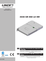
Tabella 2
Rif. Parte
AViti di chiusura coperchio
BLED per ingressi radio
CLED per allarmi di supervisione
DLED batteria periferica scarica
ELED per allarmi 24H
FTasto multifuzione
GMicroswitch antisabotaggio con foro di ssaggio
HPassaggio cavi
IDip-switch
LMorsetti uscite
MMorsetto per uscita allarme 24H periferica
NMorsetto per uscita batteria periferica scarica
OMorsetto per uscita sabotaggio ricevitore
PMorsetti alimentazione
QFori di ssaggio a muro
RJumper per il microswitch antisabotaggio
SMorsetto antenna supplementare
A
A
B
C
D
E
F
GH
I
L
M N
S
H
H
O P
Q
Q
R
1.4 IDENTIFICAZIONE DELLE PARTI
Table 2
Ref. Part
AScrew for lid xing
BLEDs for wirelss inputs
CLED for supervision alarms
DLED for wireless device low battery
ELED for 24H tamper alarm
FMultifunctional button
GAntitamper microswitch with wall xing hole
HWire passage
IDip-switch
LOutput terminal blocks
MTerminal block for device 24H alarm output
NTerminal block for device low battery
OTerminal block for device tamper
PPower supply terminal block
QWall xing holes
RJumper for microswitch tamper
STerminal block for supplementary antenna
1.4 PARTS IDENTIFICATION
Fig. 2

5
LINCE ITALIA S.p.A.
2. INSTALLAZIONE
Il ricevitore può essere installato sia su un muro utilizzando il
contenitore plastico in dotazione, sia all'interno della centrale ad
esso collegata.
2.1 MONTAGGIO A MURO
Per l’installazione a muro procedere come indicato di seguito:
• rimuovere le due viti di chiusura presenti sul coperchio del
contenitore;
• aprire il coperchio;
• con un utensile rimuovere le parti in plastica per il passaggio
dei cavi;
• far passare i cavi di collegamento attraverso l’apposita
apertura dopo aver sfondato il tassello pretagliato (H-Fig.2);
• ssare il supporto a muro utilizzando i 2 fori (Q-Fig.2)
• effettuare i collegamenti elettrici come descritti nel paragrafo
2.3;
• riposizionare il coperchio e chiuderlo utilizzando le viti tolte
in precedenza.
2.2 MONTAGGIO IN CENTRALE
In alternativa, qualora le condizioni installative lo consentano, è
possibile collocare il ricevitore all'interno della centrale stessa.
Per installare il ricevitore in questo modo, procedere come
indicato di seguito:
• rimuovere le due viti di chiusura presenti sul coperchio del
contenitore;
• aprire il coperchio;
• rimuovere le due viti che tengono la scheda sul fondo del
contenitore;
• collocare la scheda all'interno della centrale e ssarla
utilizzando del nastro bi-adesivo
• ANT: morsetti per collegamento antenna esterna;
• OUT 1÷8: morsetti uscita dispositivi radio;
• 24H: uscita tamper spositivi radio.;
• BAT: uscita stato batteria dispositivi radio:
• AS: uscita sabotaggio ricevitore;
• + - : alimentazione
2.4 IMPOSTAZIONI
Le indicazioni di seguito riportare permettono di impostare
opportunamente i parametri di funzionamento del ricevitore e
delle uscite .
Tabella 3 (il default in grassetto)
DIP Funzione OFF ON
1Memorizzazione Disattiva Attiva
2Cancellazione Disattiva Attiva
3Antisaturazione Disattiva Attiva
4Test portata radio Disattiva Attiva
5Supervisione Disattiva Attiva
6Uscite relè allarme N. C. N. A.
7Uscite relè generali N. C. N. A.
8Tipo di uscite relè Passo-passo Impulsato
NOTA: non installare la scheda ricevitore all'interno
di contenitori mettallici al ne di non inciare sulle
prestazioni della trasmissione radio. Qualora non sia
possibile fare diversamente, è consigliabile collegare
un'antenna esterna sul relativo morsetto (S-Fig.2)
2. INSTALLATION
The receiver can be placed on a wall by using the plastic case
supplied or inside the control panel to which it is connected
2.1 WALL MOUNTING
For wall mounting proceed as following:
• Remove the two screws placed on the top of the lid;
• open the lid;
• remove the plastic parts of wire passage with a tool;
• route the cables through the passages (H-Fig.2);
• mount the backplate using the 2 holes (Q-Fig.2) ;
• wiring as described in the paragraph 2.3;
• place again the lid with the screws removed previously.
2.2 CONTROL PANEL MOUNTING
When it is possible place the receiver inside the control panel
itself. To install the receiver in this way, proceed as suggest
below:
• Remove the two screws placed on the top of the lid;
• open the lid;
• remove the two screws (M-Fig.2) that keep the board on the
bottom of the case;
• place the board inside the control panel and x it by using
bi-adhesive tape.
2.3 COLLEGAMENTI ELETTRICI 2.3 ELECTRICAL WIRING
Fig. 3
• ANT: terminal block for external antenna connection;
• OUT 1÷8: terminal block related to wireless device output;
• 24H: radio device tamper output;
• BAT: battery status wireless devices output;
• AS: receiver tamper output;
• + - : power supply;
2.4 SETTINGS
The instructions below allow to set-up all the parameters of the
receiver and of the output.
Table 3 (deafult in bold)
DIP Function OFF ON
1Storage Deactivated Activated
2Erasing Deactivated Activated
3Antisaturation Deactivated Activated
4Radio test range Deactivated Activated
5Supervision Deactivated Activated
6Alarm relay outputs N. C. N. O.
7General relay output N. C. N. O.
8Type of relay otuput Step by step Impulsive
NOTE: do not install the transceiver inside metallic case
in order to avoid to affect the wireless transmission.
If it is not possible to do otherwise, it is advisable to
connect an external antenna to the corresponding
terminal block (S-Fig.2)

6
LINCE ITALIA S.p.A.
• Memorizzazione: permette di memorizzare le periferiche;
• Cancellazione: permette di cancellare le periferiche;
• Antisaturazione: richiede un modulo antisaturazione
4067GR868TP/AS che invia periodicamente una breve
segnalazione di esistenza in vita, se tale informazione viene
a mancare si attiva l’uscita “24H”; se arriva una trasmissione
valida il contatore viene azzerato.
• Test portata radio: Se attivato, il ricevitore produce un
suono ad ogni trasmissione da parte di una periferica
memorizzata e fa lampeggiare velocemente il relativo LED
per 1 minuto;
• Supervisione: per il suo funzionamento è necessario
attivare la supervisione anche sulle periferiche desiderate
facendo riferimento al relativo manuale. In questo modo le
periferiche con supervisione attiva inviano periodicamente
un segnale di esistenza in vita;
NOTA: le funzioni supervisione e antisaturazione non
possono convivere
• Uscite relè di allarme: seleziona il funzionamento delle
uscite relè di allarme in modalità NC o NA;
• Uscite relè generali: seleziona il funzionamento delle
uscite relè generali in modalità NC o NA;
• Tipo di uscita relè: permette di selezionare il funzionamento
delle uscite di allarme in modalità monostabile o bistabile;
3. MEMORIZZAZIONE
Per memorizzare i dispositivi seguire i passi riportati qui di
seguito:
1. Portare il DIP1 in ON;
2. scegliere il canale radio che si vuole memorizzare (LED
lampeggiante) premendo il tasto multifuznione no a
selezionare il canale desiderato, se diverso dal primo libero
che viene proposto di default;
3. trasmettere la trama di memorizzazione dal dispositivo
da apprendere facendo riferimento al relativo manuale di
utilizzo;
4. alla ricezione della trama, il ricevitore conferma la
memorizzazione con l’accensione simultanea dei LED
accompagnata da un breve suono del buzzer. Il LED del
canale appena memorizzato si accende in modo sso e il
ricevitore punterà automaticamente il primo canale radio
disponibile facendo lampeggiare il LED corrispondente;
5. per memorizzare altre periferiche (no a un massimo di 8)
ripetere i passi da 2 a 5;
6. portare il DIP1 in OFF per uscire dalla procedura.
NOTA:
Se il ricevitore riconosce che la trama che si tenta di memorizzare
è già presente in memoria, emette alcuni beep consecutivi per
segnalare l’anomalia.
4. TEST PORTATA RADIO
Il test della portata radio permette di vericare la corretta
ricezione delle trasmissioni da parte del ricevitore. Per entrare
nella procedura di “Test Portata Radio” posizionare il DIP4 in ON.
Provocare una trasmissione sui rilevatori da controllare. Alla
ricezione della trama il ricevitore emette una sequenza di 7
brevi suoni del buzzer ed il LED del canale radio su cui è stato
trasmesso l’allarme visualizza la ricezione con un lampeggio
intermittente.
Terminato il test della portata, posizionare il DIP 4 in OFF per
uscire dalla procedura. Tutti i LED di memoria lampeggianti
durante il test vengono spenti automaticamente.
• Storage: it allows to storage the GR868 wireless devices;
• Erasing: it allows to erase the GR868 wireless devices;
• Antisaturation: a 4067GR868TP/AS transmitter is
necessary to send periodically an existence in life signal. If
this information lacks the “24H” output will be activated.
• Wireless test range: when activated, the receiver outputs
a sound on each transmission from a stored device and
quickly blinks its LED for 1 minute;
• Supervision: For its operation, it is necessary to activate
the supervision also on the peripherals desired by referring
to its manual. In this way, the devices periodically send a
signal of existence in life.
NOTE: supervision and anti-saturation functions can not
coexist;
• Alarm relay outputs: it selects the operation of the alarm
relay outputs in NC or NO mode;
• General relay outputs: it selects the operation of the
general relay outputs in NC or NO mode;
• Type of relay outputs: it allows to select the operation of
alarm outputs in monostable or bistable mode.
3. STORING
To store the devices follow the steps reported below:
1. Switch the DIP1 ON;
2. Select the wireless channel you want to store (ashing LED)
by pressing the multi-function button until you select the
desired channel, if different from the rst free one showed;
3. transmit the storage message from the device to learn by
referring to its user manual;
4. when receiving the storage message, the receiver conrms
the storage with the simultaneous switch-on of the LEDs
accompanied by a brief sound of the buzzer. The newly
stored channel LED lights up steadily and the receiver will
automatically switches to the rst wireless channel available
by blinking the corresponding LED;
5. to store other peripherals (up to a maximum of 8) repeat
steps 2 through 5;
6. switch the DIP1 to OFF to exit the procedure;
NOTE:
If the receiver recognizes that the device you are trying to store
is already in memory, it produces some consecutive beeps to
signal the fault.
4. WIRELESS RANGE TEST
The wireless range test allows to verify the correct reception
of transmissions by the receiver. To enter the "Wireless Range
Test" procedure, switch DIP4 in ON:
Provide a transmission of the detectors to be monitored. When
receiving the message, the receiver emits a sequence of 7 short
sounds of the buzzer and the LED on the wireless channel
on which the alarm is transmitted displays the reception with
intermittent ashing.
When the range test is complete, switch DIP 4 in OFF to exit
the procedure. All ashing LEDs during the test are switched off
automatically.

7
LINCE ITALIA S.p.A.
5. ANTISATURAZIONE
Quando abilitata con DIP 3 in ON, questa funzione permette di
generare un allarme quando non viene rilevata la trasmissione
inviata dal modulo contatti 4067GR868TP/AS. . La segnalazione
di saturazione viene visualizzata sul LED di supervisione e viene
aperto per 2 secondi il relè ”24H”.
6. SUPERVISIONE
Quando abilitata con DIP 5 in ON, questa funzione permette di
controllare l’esistenza in vita di tutte le periferiche radio abilitate.
Ad intervalli variabili tutti i rilevatori trasmettono un codice di
identicazione. Quando questo codice non viene rilevato, il
ricevitore accende il LED di antisaturazione e apre il relè “24H”.
Interrogando con il tasto multifuzione, è possibile vericare sui
LED 1 - 8 quale rilevatore ha inviato la segnalazione.
NOTA:
Non potendo coesistere le funzioni di antisaturazione e
supervisione, nel caso in cui si dovessero erroneamente
impostare sia il DIP 3 che il DIP 5 in ON si otterrà la sola funzione
di antisaturazione.
7. STATO BATTERIA
Quando la tensione della batteria di un rilevatore scende sotto
la soglia prestabilita, il ricevitore accende il LED di stato batteria
ed apre l'uscita “BAT”. Interrogando con il tasto multifunzione,
è possibile vericare sui LED 1 – 8 quale rilevatore ha inviato
la segnalazione. La segnalazione di stato batteria scompare
quando avviene una trasmissione di batteria carica.
8. CANCELLAZIONE
8.1 CANCELLAZIONE SELETTIVA
Per cancellare selettivamente i dispositivi seguire i passi riportati:
1. Portare il DIP2 in ON;
2. il dispositivo punterà il primo canale radio memorizzato
facendo lampeggiare il LED corrispondente. Eventuali altri
canali radio memorizzati vengono segnalati dall’accensione
stabile del LED corrispondente;
3. E’ ora possibile effettuare la cancellazione in due differenti
modi:
• Automatico: con questa operazione si cancellano le
periferiche, indipendentemente dal canale radio al momento
puntato, facendo trasmettere la trama di memorizzazione
dalla periferica che si desidera cancellare;
• Manuale: Seleziona il canale radio da cancellare utilizzando
il tasto multifunzione premendolo più volte no a far
lampeggiare il LED corrispondente, rilasciarlo e e premerlo
in modo continuativo per più di 3 secondi;
4. alla ricezione della trama, il ricevitore conferma la
cancellazione con l’accensione simultanea dei LED
accompagnata da un breve suono del buzzer;
5. il LED del canale appena cancellato si spegne ed il ricevitore
punta automaticamente il primo canale radio successivo
memorizzato;
6. ripetere i passi da 2 a 4 per tutti i canali che si desidera
cancellare;
7. portare il DIP2 in OFF per uscire dalla procedura.
5. ANTISATURATION
When enabled with DIP 3 in ON, this function generates an
alarm when the transmission sent by the contact module
4067GR868TP/AS is not recognized. The saturation signal is
displayed on the supervision LED and the relay "24H" opens for
2 seconds.
6. SUPERVISION
When enabled with DIP 5 in ON, this feature allows you to
monitor the existence in life of all enabled radio devices. At
variable intervals, all the detectors transmit an identication
code. When this code is not recognized, the receiver turns on the
anti-saturation LED and opens the "24H" relay. By interrogating
with the multifunction button, you can check on LEDs 1 - 8 which
detector has sent the signal.
NOTE:
Because the anti-saturation and supervision functions don't work
together, in case you mistakenly set both DIP 3 and DIP 5 in ON,
only the the anti-saturation function will be activated.
7. BATTERY STATUS
When a battery voltage drops below the preset threshold, the
receiver turns on the low battery status LED and opens the "BAT"
output. By interrogating with the multifunction key, you can check
on LEDs 1 - 8 which detector has sent the signal. The battery
status warning disappears when a charged battery transmission
occurs.
8. ERASING
8.1 SELECTIVE ERASING
To selectively erase the devices follow the steps reported below:
1. Switch the DIP2 ON;
2. the device will point to the rst stored wireless channel by
ashing the corresponding LED. Any other stored channels
are signaled by the stable power-on of the corresponding
LED;
3. derasing is now possible in two different ways:
• Automatic: with this operation, the peripherals are deleted,
regardless of the wireless channel showed, by transmitting
the storage message from the device that you want to erase;
• Manual: Select the wireless channel to be erased using
the multifunction key by pressing it repeatedly until the
corresponding LED ashes; release and press it continuously
for more than 3 seconds;
4. When receiving the message, the receiver conrms the
cancellation with the simultaneous ignition of the LEDs
accompanied by a short sound of the buzzer;
5. The LED of the newly deleted channel will turn off and the
receiver will automatically point to the next stored radio
channel;
6. repeat the steps from 2 to 4 for all the channels that you
want to erase;
7. switch the DIP2 OFF to exit from the procedure.

001530/00202AC
LINCE ITALIA S.p.A
Via Variante di Cancelliera, snc
00040 ARICCIA (Roma)
Tel. +39 06 9301801
Fax +39 06 930180232
info@lince.net
www.lince.net
8.2 CANCELLAZIONE TOTALE
Posizionare il DIP1 e DIP2 in ON; l’ingresso nella procedura
di cancellazione totale è segnalato, per alcuni secondi, dal
rapido lampeggio dei LED 1 – 8. Durante questo tempo è
possibile interrompere la cancellazione posizionando i DIP1
e 2 in OFF. Se non si interrompe la procedura, il ricevitore
conferma la cancellazione totale con l’accensione simultanea
dei LED accompagnata da 3 brevi suoni del buzzer. Terminata
la cancellazione posizionare i DIP1 e 2 in OFF per uscire dalla
procedura.
9. MANUTENZIONE E VERIFICHE PE-
RIODICHE
ATTENZIONE! Per rimuovere sporcizie particolar-
mente evidenti NON utilizzare prodotti a base di clo-
ro, prodotti abrasivi oppure alcool.
1. Pulire il coperchio con un panno inumidito con acqua.
2. Ripassare con un panno asciutto.
10. SMALTIMENTO E ROTTAMAZIONE
1. Svitare le viti che tengono sso il coperchio frontale e rimuo-
verlo.
2. Scollegare la scheda: sulla morsettiera scollegare tutti i mor-
setti (v. Fig. 3).
3. Dividere le parti in base alla loro tipologia e smaltirle in accor-
do con le leggi vigenti.
ATTENZIONE!
Non disperdere nell’ambiente i componenti ed ogni
altro materiale del prodotto.
Rivolgersi a consorzi abilitati allo smaltimento ed al riciclag-
gio dei materiali.
8.2 TOTAL ERASING
Set the DIP1 and DIP2 to ON, the start of the total erasure
procedure is signaled for a few seconds by the rapid ashing
of the LEDs from 1 to 8. During this time you can interrupt the
deletion by positioning the DIP1 and the 2 in OFF. If the procedure
is not interrupted, the receiver conrms the total deletion with the
simultaneous power on of the LEDs accompanied by three short
sounds of the buzzer. After the deletion, place the DIP1 and 2 in
OFF to exit the procedure.
9. MAINTENANCE AND PERIODIC
CHECKS
IMPORTANT!
Do NOT use chlorine-based or abrasive products or
alcohol to remove particularly noticeable dirt.
1. Clean the lid with a cloth dampened with water.
2. 2. Wipe with a dry cloth.
10. DISPOSAL AND SCRAPPING
1. Unscrew the screws that fasten the front lid and remove it.
2. Disconnect the board: disconnect all the terminals on the ter-
minal block (see Fig. 3).
3. Divide the parts by type and dispose of them in accordance
with applicable laws.
IMPORTANT!
Do not dispose of the components or any other pro-
duct material in the environment.
Seek the assistance of companies authorised to dispose of
and recycle waste materials.
1/8