047U53088 02/2016
R206B
ValVola di bilanciamento statico
Static balancing valve
Dati tecnici - Technical data
• Campo di temperatura di esercizio: 5÷110 °C
• Pressione massima di esercizio: 25 bar
• Temperature range: 5÷110 °C
• Maximum working pressure: 25 bar
Materiali - Materials
• Corpo: ottone antidezincicazione DZR (EN 12165 - CW602N)
• Volantino: ABS, colore bianco
• Handwheel: ABS, white color
• Body: dezincification resistant brass DZR (EN 12165 - CW602N)
Descrizione - Description
Il bilanciamento è fondamentale per il risparmio dell’energia utilizzata negli impianti idrotermosanitari. Le R206B sono
valvole di bilanciamento statico, che permettono una regolazione graduale e precisa della portata. Le valvole R206B sono
dotate di un ussimetro a orizio calibrato (principio Venturi), ovvero con Kv sso, che tramite le prese di pressione (in
dotazione o come accessorio opzionale a seconda delle versioni) e di un manometro dierenziale, permette di misurare
accuratamente la portata eettivamente circolante.
The balancing is essential for saving the energy used in hydro-thermo-sanitary systems. The R206B are static balancing valves,
that permit a gradual and precise regulation of the flow rate. The R206B valves have a flowmeter with calibrated orifice (Venturi
principle), that is with fixed Kv, that through the pressure outlets (depending on the versions they are provided with or they are
optional accessory) and a differential manometer, permits to measure carefully the flow rate that is really circulating.
Caratteristiche principali - Main features
• Attacco per scarico G 1/4”F
• Portasonde per ago Ø 3 mm e lunghezza 30÷40 mm
• Funzione di chiusura
• Possibilità di preregolazione
• Flussimetro Venturi per misurazioni di portata tramite prese di pressione
• Drain connection G 1/4”F
• Sensor holder for needle Ø 3 mm and lenght 30÷40 mm
• Closing function
• Presetting possibility
• Venturi flowmeter for flow rate measurement by means of pressure probes
Funzionamento - Operation
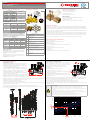
Preregolazione - Presetting
Le valvole R206B sono dotate di un meccanismo di memoria meccanica
dell’apertura (preregolazione). Questo meccanismo opera limitando la
corsa della manopola (rif.C - g.2) tramite una vite di bloccaggio (rif.G - g.2).
La preregolazione si eettua nel seguente modo:
• Scegliere la portata desiderata Q in funzione della pressione dieren. ∆p;
• Tramite il diagramma in gura 3, determinare la regolazione da
eettuare per ottenere la portata Q desiderata in funzione della
pressione dierenziale ∆p a seconda della taglia della valvola;
• Eettuare la regolazione della valvola R206B tramite la manopola (rif.C
- g.2), sulla scala di regolazione (rif.F - g.1);
• Avvitare in senso orario no a battuta la vite di bloccaggio della
preregolazione (rif.G - g.2) utilizzando una chiave a brugola da 1,5 mm
per le versioni da 1/2”, 3/4”, 1”, 1-1/4” o da 2 mm per le versioni da 1-1/2”, 2”.
R206B valves are equipped with a mechanism of mechanical memory of the opening (pre-regulation). This mechanism works by
limiting the handle stroke (ref. C – fig.2) through a locking screw (ref.G – fig.2).
Operationally the preregulation shall be effected as follows:
• Select the desired flow rate Q depending on the differential pressure Δp;
• Through the diagram of figure 3, determine the regulation to be carried out to obtain the desired flow rate Q depending on the
differential pressure Δp according to the valve size.
• Make the regulation of the R206B valve by means of the handle (ref.C-fig.2), on the regulation scale (ref. F – fig.1);
• Screw clockwise until it stops the locking screw of the pre-regulation (ref.G-fig.2) by using an Allen key of 1,5 mm for versions 1/2”,
3/4”, 1”, 1-1/4” or 2 mm for versions 1-1/2”, 2”.
Versioni e codici - Versions and codes
Product code Connections
With probes Without probes
R206BY003 R206BY013 1/2”
R206BY004 R206BY014 3/4”
R206BY005 R206BY015 1”
R206BY006 R206BY016 1-1/4”
R206BY007 R206BY017 1-1/2”
R206BY008 R206BY018 2”
Kv valvole - Valves Kv
Connections Kv (Venturi ow meter) Kv (complete valve)
1/2” 4,0 2,7
3/4” 7,5 5,5
1” 11,0 7,0
1-1/4” 13,5 9,5
1-1/2” 24 18,5
2” 31 25,5
Valori di portata relativi alla pressione dierenziale per
ussimetro Venturi (*) oppure per la valvola completa (**)
Flowrate values related to dierential pressure on Venturi
owmeter (*) or for the complete valve (**)
Flow rate (l/h)
Connections 0,5 kPa (*) 3 kPa (*) 10 kPa (**)
1/2” 280 690 860
3/4” 530 1300 1740
1” 780 1900 2220
1-1/4” 950 2340 3000
1-1/2” 1700 4160 5850
2” 2190 5370 8065
Componenti - Components
Calcolo della portata - Flowrate calculation
Le valvole di bilanciamento R206B sono dotate di un ussimetro a
orizio calibrato (principio Venturi), ovvero con Kv sso, che tramite
le prese di pressione (rif.A, B - g.4) e un manometro dierenziale,
permette di calcolare la portata eettivamente circolante.
La portata Q può essere determinata con la seguente formula:
Q = Kvventuri • √∆p
Per i valori di Kvventuri vedere tabella “Kv valvole”.
Il ∆p va misurato tramite le prese di pressione.
Per liquidi con densità ρ diversa da quella dell’acqua, utilizzare la
formula: Q = Kvventuri • √∆p / ρ
In alternativa alla formula si può utilizzare il diagramma in gura 5.
Con il valore ∆p misurato, si può determinare la portata Q a seconda
della taglia della valvola.
R206B balancing valves are equipped with a flowmeter having calibrated orifice (Venturi principle), that is with fixed Kv, that through
the pressure outlets (ref.A-fig.4) and a common differential manometer, permits to calculate the really circulating flow rate.
The flow rate Q can be determined with the following formula: Q = Kvventuri • √∆p
Refer to the table “Valves Kv” for the Kvventuri values. Δp has to be measured through the pressure outlets.
Use the following formula for the liquids having density p different from water: Q = Kvventuri • √∆p / ρ
As alternative to the formula, you can use the diagram in figure 5: with the measured Δp value, the flow rate Q can be determined
according to the valve size.
4 1
32
Avvertenza - Warning
Possono vericarsi tralamenti di acqua bollente attraverso le prese di pressione durante l’inserimento delle sonde.
Indossare indumenti e occhiali protettivi per prevenire danni sici personali durante la misura della pressione.
Non usare lubricanti sulle sonde per agevolare l’inserimento nelle prese. Se necessario bagnare semplicementi le sonde
con acqua pulita.
Non lasciare l’ago di misura nella presa di pressione troppo a lungo, poichè ciò potrebbe produrre delle perdite.
Leakage of hot water can occur through the pressure outlets during the sensor introduction of the sensors. Wear protective clothes
and glasses in order to prevent personal physical damages during the pressure measure.
Do not use lubricants on the sensors to ease the outlet insertion. If needed simply wet the sensors with clean water.
Do not leave the measure needle too much time in the pressure outlet, as it could cause leakages.
Fig. 1
A B
H
C
F
G
A B
V
D
H
E
Legenda - Legend
ASonda alta pressione
High pressure probe
BSonda bassa pressione
Low pressure probe
CVolantino
Handwheel
DScarico 1/4” F
Drain 1/4”F
EKv del ussimetro Venturi
Kv of the Venturi flow meter
FScala per regolazione 0÷100 % (20 posizioni)
Scale for 0÷100 % setting (20 positions)
GVite di preregolazione (limita la corsa)
Presetting screw (limiting the stroke)
H
Testa rimovibile (per eettuare la regolazione) con Kv
venturi stampato
Removable head (for presetting) with imprinted the Ven-
turi Kv
VFlussimetro Venturi
Venturi flow meter
Accessori - Accessories
• P206Y001: kit portasonde (n° 2) per la determinazione della portata
tramite misurazione della pressione dierenziale, attacchi G 1/4”M.
• R225EY001: manometro dierenziale.
• P206Y001: sensors holder (no. 2) kit for the flow rate determination
through measurement of the differential pressure, G 1/4”M connections.
• R225EY001: differential manometer.
Q ∆p PRESETTING REGULATION
desired values Fig. 3
Fig. 2
C
F
G
Q
∆p
V
Q
A B
∆p
Fig. 4
0 1 10 100
[kPa]
0 0,1 1 10
[m c.a.]
0 0,01 0,1 1
[bar]
Q [m3/h]
0
1
10
100
1/2”
3/4”
1”
1 1/4”
1 1/2”
2”
Q
∆p
Venturi
calculated
value
Fig. 5

047U53088 02/2016
R206B
ValVola di bilanciamento statico
Static balancing valve
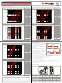
Perdite di carico - Pressure losses
5 6
Additional information
For further information, visit the website www.giacomini.com or contact the technical service:
' +39 0322 923372 6 +39 0322 923255 * [email protected]om
This information is intended as an example. Giacomini S.p.A. reserves the right to modify the contents - at any time and without prior warning
- for technical or commercial reasons. The information in this technical sheet does not exempt the user from scrupulously observing the existing
regulations and standards relating to good technical practices. Giacomini S.p.A. Via per Alzo, 39 - 28017 San Maurizio d’Opaglio (NO) Italy 7 8
1/2” Setting Kv
0,1 1,0
Q [m3/h]
5 10 20 30
40
50
60
70
80
90
100
Settings
0,01
0,10
1,00
∆p [bar]
1
10
100
∆p [kPa]
1
0,1
10
∆p [m c.a.]
100 2,70
95 2,54
90 2,48
85 2,34
80 2,18
75 1,99
70 1,71
65 1,59
60 1,48
55 1,41
50 1,33
45 1,28
40 1,19
35 1,09
30 0,98
25 0,92
20 0,83
15 0,73
10 0,63
5 0,53
3/4” Setting Kv
0,1 1,0 10,0
Q [m3/h]
Setting 5 10 20 30 40 50 60 7080
90
100
0,01
0,10
1,00
∆p [bar]
1
10
100
∆p [kPa]
1
0,1
10
∆p [m c.a.]
100 5,50
95 5,20
90 5,00
85 4,80
80 4,57
75 4,35
70 3,95
65 3,50
60 2,88
55 2,37
50 2,00
45 1,81
40 1,58
35 1,39
30 1,24
25 1,10
20 0,96
15 0,85
10 0,75
5 0,62
1” Setting Kv
0,1 1,0 10,0
Q [m3/h]
Settings 5 10 20 30 40 50 60 7080 90100
0,01
0,10
1,00
∆p [bar]
1
10
100
∆p [kPa]
1
0,1
10
∆p [m c.a.]
100 7,00
95 6,59
90 6,25
85 5,95
80 5,49
75 5,03
70 4,86
65 4,29
60 3,89
55 3,32
50 2,92
45 2,50
40 2,14
35 1,81
30 1,47
25 1,37
20 1,14
15 0,98
10 0,83
5 0,64
1-1/4” Setting Kv
0,1 1,0 10,0
Q [m3/h]
Settings 5 10 20 30 40 50 60 7080 90100
0,01
0,10
1,00
∆p [bar]
1
10
100
∆p [kPa]
1
0,1
10
∆p [m c.a.]
100 9,50
95 8,98
90 8,55
85 7,97
80 7,60
75 7,05
70 6,46
65 5,86
60 5,50
55 4,89
50 4,39
45 4,04
40 3,69
35 3,25
30 2,66
25 2,21
20 1,79
15 1,53
10 1,21
5 0,73
1-1/2” Setting Kv
1,0 10,0 100,0
Settings 5 10 20 30 40 50 6070
80
90
100
0,01
0,10
1,00
∆p [bar]
1
10
100
∆p [kPa]
1
0,1
10
∆p [m c.a.]
Q [m3/h]
100 18,50
95 17,80
90 17,35
85 16,98
80 16,40
75 15,84
70 15,23
65 14,29
60 13,19
55 12,28
50 11,21
45 10,13
40 9,18
35 8,41
30 7,56
25 6,74
20 5,80
15 4,67
10 3,84
5 3,02
2” Setting Kv
1,0 10,0 100,0
Q [m3/h]
Settings 5 10 20 30 40 50 60 70 80 90100
0,01
0,10
1,00
∆p [bar]
1
10
100
∆p [kPa]
1
0,1
10
∆p [m c.a.]
100 25,50
95 24,08
90 23,21
85 21,64
80 19,98
75 18,95
70 17,64
65 16,53
60 14,72
55 13,33
50 12,06
45 11,08
40 9,98
35 8,99
30 8,02
25 7,26
20 6,24
15 5,13
10 4,18
5 3,36
Dimensioni - Dimensions
C
D
B
F
A E
Connections DN A [mm] B [mm] C [mm] D [mm] E [mm] F [mm]
1/2” 15 131 95 119 25 64 25
3/4” 20 131 101 118 28 64 25
1” 25 131 110 122 32 64 25
1-1/4” 32 137 120 129 35 64 25
1-1/2” 40 163 140 166 39 64 25
2” 50 169 154 172 45 70 25
Installazione - Installation
• La valvola deve essere installata mantendo libero l’accesso alle prese
di pressione, al rubinetto di scarico e alla manopola di regolazione.
• La valvola e la tubazione sulla quale è installata devono avere
lo stesso diametro nominale.
• Eettuare il lavaggio dell’impianto prima di installare la valvola.
• Prevedere un ltro a monte della valvola per proteggerla da
eventuali impurità.
• Rispettare il senso di usso indicato sul corpo della valvola.
• La valvola può essere montata sia su tubazioni orizzontali che verticali.
• Se la valvola è installata dopo un tratto di tubazione curva
si consiglia di mantenere una tubazione rettilinea a monte
della valvola di una lunghezza minima pari a 5 volte il diametro
nominale (Dn) della valvola stessa.
Se è presente un circolatore immediatamente a monte
della valvola, la lunghezza della tubazione rettilinea minima
consigliata è 10 volte il diametro nominale (Dn) della valvola stessa.
• The valve must be installed maintaining free access to the pressure probes, drain and handwheel.
• The valve and the pipe on which it is installed must have the same nominal diameter.
• Wash the system before installing the R206B valve.
• To protect the valve from possible impurities, insert a filter upstream the valve.
• Respect the flow direction indicate on the valve’s body.
• The valve can be mounted on horizontal or vertical pipes.
• If the valve is installed after a curved pipe portion is recommended to maintain a straight pipe before the valve to a minimum
length equal to 5 times the nominal diameter (Dn) of the valve itself.
If there is a circulator immediately before the valve, the minimum recommended length of the straight pipe is 10 times the nominal
diameter (Dn) of the valve itself.
R206B
5 x Dn 2 x Dn
R206B
10 x Dn 2 x Dn
R206B
5 x Dn 2 x Dn
R206B
10 x Dn 2 x Dn
-
 1
1
-
 2
2


in altre lingue
Documenti correlati
-
Giacomini P225E Istruzioni per l'uso
-
-
-
-
-
-
-
-
-