CAME ASTA MODULARE 803XA-0640 Manuale del proprietario
- Tipo
- Manuale del proprietario

FA01899M4A
10/2022
803XA-0640
IT Italiano
EN English
FR Français
RU Русский
CAME S.p.A.
Via Martiri Della Libertà, 15
31030 - Dosson di Casier -
Treviso - Italy
tel. (+39) 0422 4940 - fax.
(+39) 0422 4941
www.came.com - info@
came.com
A
90
60
2610 2610
Ø 3
Ø 3
B
X
10
x2
C
FA01899M4A - 10/2022
FA01899M4A - 10/2022
803XA-0640

ITALIANO
Descrizione
803XA-0640
Asta modulare in alluminio verniciato bianco, completa di tappo, composta da: n. 2
aste 90 x 60 L = 2600 mm, giunto, rinforzo interno, profili di copertura cava e profilo
in gomma antiurto.
Asta non compatibile con rastrelliere 803XA-0340 e 803XA-0350. Non
compatibile con piedino mobile 803XA-0330. Non compatibile con elettromagnete
803XA-0360.
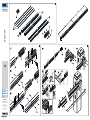
A Descrizione delle parti
1 Rinforzo Interno
2 Profili copri cava (4)
3 Sezioni asta (2)
4 Guaina anti-urto (2)
5 Giunzione sezioni asta
6 Viti di fissaggio giunzione 4.8x16mm UNI6954 (8)
Installazione
B Montaggio dell'asta
Infilare la giunzione per circa metà della sua lunghezza in una sezione dell'asta.
Eseguire quattro fori (due per lato) di 3 millimetri su asta e giunzione. Rispettare le
distanze indicate in figura.
Fissare giunzione e asta su ambo i lati con le viti in dotazione.
Infilare sulla giunzione la seconda sezione dell'asta.
Far combaciare i bordi delle due sezioni dell'asta.
Eseguire i quattro fori per il fissaggio.
Fissare giunzione e asta su ambo i lati con le viti in dotazione.
C Fissaggio dell'asta alla barriera
Inserire il rinforzo all'interno dell'asta.
Fissare all'asta la flangia e la piastra intermedia.*
Fissare l'asta alla piastra di fissaggio della barriera.
Inserire, nell'apposita scanalatura, la prima coppia di profili copricava su entrambi
i lati dell'asta.
Tagliare la seconda coppia della stessa misura della cava dell'asta meno 10 milli-
metri ed inserirla nell'apposita scanalatura.
Inserire le due guaine di gomma anti-urto nell'apposita scanalatura.
Tagliare la parte eccedente della seconda guaina, facendola combaciare con il tappo
terminale.
Fissare il tappo di chiusura dell'asta con le apposite viti.
Inserire la copertura di protezione anti-cesoiamento della barriera sul copri-attacco
asta e fissarla con le viti.
*In dotazione con la barriera.
Dismissione e smaltimento
Il prodotto è conforme alle direttive applicabili, vigenti al momento della fabbricazione.
Non disperdere nell’ambiente l’imballaggio e il dispositivo alla fine del ciclo di vita,
ma smaltirli seguendo le norme vigenti nel paese di utilizzo del prodotto. I componenti
riciclabili riportano simbolo e sigla del materiale.
I DATI E LE INFORMAZIONI INDICATE IN QUESTO MANUALE SONO DA RITENERSI
SUSCETTIBILI DI MODIFICA IN QUALSIASI MOMENTO E SENZA OBBLIGO DI PREAVVISO.
LE MISURE, SE NON DIVERSAMENTE INDICATO, SONO IN MILLIMETRI.
ENGLISH
Description
803XA-0640
Painted white modular aluminium boom, complete with cap and made up of: 2 x booms
90 x 60 L = 2600 mm, with connector piece, internal reinforcement, groove cover strips
and impact protection rubber profile.
Boom not compatible with skirts 803XA-0340 and 803XA-0350. Not compatible
with mobile foot 803XA-0330. Not compatible with electromagnet 803XA-0360.
A Description of parts
1 Internal reinforcement
2 Groove cover strips (4)
3 Boom sections (2)
4 Impact protection profiles (2)
5 Boom section connector piece
6 Connector piece fixing screws 4.8x16mm UNI6954 (8)
Installation
B Boom installation
Slot the connector piece approximately half into the boom section.
Drill four holes (two on each side) measuring 3 mm into the boom and connector
piece. Use the measurements specified in the figure shown.
Secure the connector piece and boom on both sides using the screws supplied.
Slot the second boom section onto the connector piece.
Ensure the edges of the two boom sections are flush together.
Drill four holes to secure in place.
Secure the connector piece and boom on both sides using the screws supplied.
C Fastening the boom to the barrier
Insert the reinforcement inside the boom.
Fix the flange and the intermediate plate to the boom.*
Fasten the boom to the anchoring plate on the barrier.
Press the first pair of groove cover strips into the groove on both sides of the boom.
Cut the second pair of groove cover strips to the same length as the boom groove
minus 10 millimetres, and press in.
Slot the two impact protection rubber profiles into the grooving.
Cut off the excess of the second rubber profile so it is positioned flush with the end
cap.
Use the screws to fasten the boom end cap.
Fit the shearing protection cover for the barrier onto the boom attachment cover and
secure using the screws.
*Supplied with barrier.
Dismantling and disposal
This product complies with the applicable standards in force at the time of manufacturing.
Dispose of the packaging and the device responsibly at the end of its life cycle, in
compliance with the laws in force in the country where the product is used. The
recyclable components are marked with the material symbol and ID.
THE DATA AND INFORMATION IN THIS MANUAL MAY BE CHANGED AT ANY TIME AND
WITHOUT NOTICE.
MEASUREMENTS ARE IN MILLIMETRES, UNLESS STATED OTHERWISE.
FRANÇAIS
Description
803XA-0640
Lisse modulaire en aluminium peint blanc, avec embout, composée des éléments
suivants: 2 lisses 90 x 60 L = 2600 mm, joint, renfort interne, profilés couvre-joint et
profil en caoutchouc anti-choc.
Lisse incompatible avec les tabliers 803XA-0340 et 803XA-0350. Incompatible
avec le pied mobile 803XA-0330. Incompatible avec l'électro-aimant 803XA-0360.
A Description des parties
1 Renfort interne
2 Profilés couvre-joint (4)
3 Sections de lisse (2)
4 Gaine anti-choc (2)
5 Jonction sections de lisse
6 Vis de fixation jonction 4.8x16mm UNI6954 (8)
Installation
B Montage de la lisse
Enfiler la jonction sur environ la moitié de sa longueur dans une section de la lisse.
Percer quatre trous (deux de chaque côté) de 3 millimètres sur la lisse et la jonction.
Respecter les distances indiquées sur la figure.
Fixer la jonction et la lisse des deux côtés à l'aide des vis fournies.
Enfiler la deuxième section de la lisse sur la jonction.
Faire correspondre les bords des deux sections de la lisse.
Percer les quatre trous de fixation.
Fixer la jonction et la lisse des deux côtés à l'aide des vis fournies.
C Fixation de la lisse à la barrière
Introduire le renfort dans la lisse.
Fixer la bride et la plaque intermédiaire sur la lisse.*
Fixer la lisse à la plaque de fixation de la barrière.
Introduire des deux côtés de la lisse la première paire de profilés couvre-joint dans
la rainure spécifique.
Couper la deuxième paire de profilés couvre-joint de sorte à ce qu’ils soient de
la même longueur que le joint de la lisse moins 10 millimètres et l'introduire dans la
rainure spécifique.
Introduire les deux gaines en caoutchouc anti-choc dans la rainure spécifique.
Couper la partie en trop de la deuxième gaine, en la faisant coïncider avec l'embout.
Fixer le couvercle de la lisse à l'aide des vis prévues à cet effet.
Appliquer le carter de protection anti-cisaillement de la barrière sur le cache-plaque
de fixation de la lisse et le fixer à l'aide des vis.
*Fourni avec la barrière.
Mise au rebut et élimination
Ce produit est conforme aux directives applicables, en vigueur lors de sa fabrication.
Ne pas jeter l'emballage et le dispositif dans la nature au terme du cycle de vie de ce
dernier, mais les éliminer selon les normes en vigueur dans le pays où le produit est
utilisé. Le symbole et le sigle du matériau figurent sur les composants recyclables.
LE CONTENU DE CE MANUEL EST SUSCEPTIBLE DE SUBIR DES MODIFICATIONS À
TOUT MOMENT ET SANS AUCUN PRÉAVIS.
LES DIMENSIONS SONT EXPRIMÉES EN MILLIMÈTRES, SAUF INDICATION CONTRAIRE.
РУССКИЙ
Описание
803XA-0640
Модульная стрела из окрашенного алюминия, белая. Комплектация: 2 модуля
стрелы длиной 2600 мм, 90 x 60 мм, с концевой заглушкой, соединителем,
внутренней вставкой, профилями для паза и защитным резиновым демпфером.
Стрела несовместима со шторками 803XA-0340 и 803XA-0350.
Несовместима с подвижной опорой 803XA-0330. Несовместима с
электромагнитом 803XA-0360.
A Описание компонентов
1 Усилительная вставка
2 Профили для паза (4)
3 Модули стрелы (2)
4 Защитный демпфер (2)
5 Соединитель для модулей стрелы
6 Винты крепления соединителя 4.8x16mm UNI6954 (8)
Монтаж
B Монтаж стрелы
Вставьте соединитель в модуль стрелы на половину его длины.
Рассверлите четыре отверстия (по два с каждой стороны) диаметром 3 мм на
стреле и соединителе. Соблюдайте расстояния, указанные на рисунке.
Зафиксируйте соединитель и стрелу с двух сторон прилагаемыми винтами.
Установите второй модуль стрелы на соединитель.
Состыкуйте торцы двух модулей стрелы.
Рассверлите четыре отверстия для крепления.
Зафиксируйте соединитель и стрелу с двух сторон прилагаемыми винтами.
C Крепление стрелы на шлагбауме
Вставьте усиление внутрь стрелы.
Закрепите на стреле кронштейн и пластину крепления стрелы.*
Закрепите стрелу на фланце крепления шлагбаума.
Вставьте первую пару профилей в специальный паз по обеим сторонам стрелы.
Отрежьте вторую пару профилей паза той же длины, что и паз, за вычетом 10
мм. После чего вставьте профили в соответствующий паз.
Вставьте два демпфера в специально предусмотренный паз.
Отрежьте лишнюю часть второго демпфера, состыковав его с концевой
заглушкой.
Установите торцевую заглушку стрелы соответствующими винтами.
Установите декоративную защитную накладку шлагбаума и зафиксируйте с
помощью прилагаемых винтов.
*Аксессуар прилагается в комплекте со шлагбаумом.
Утилизация
Изделие соответствует требованиям применимых директив, действовавших на
момент изготовления.
Не выбрасывайте упаковку и устройство совместно с бытовыми отходами.
Утилизируйте их в соответствии с требованиями законодательства, действующего
в стране установки изделия. Пригодные для повторного использования
компоненты отмечены специальным символом с обозначением материала.
СОДЕРЖАНИЕ ЭТОГО РУКОВОДСТВА МОЖЕТ БЫТЬ ИЗМЕНЕНО В ЛЮБОЕ ВРЕМЯ
БЕЗ ПРЕДВАРИТЕЛЬНОГО УВЕДОМЛЕНИЯ.
ВСЕ РАЗМЕРЫ ПРИВЕДЕНЫ В МИЛЛИМЕТРАХ, ЕСЛИ НЕ УКАЗАНО ИНОЕ.
FA01899M4A - 10/2022
FA01899M4A - 10/2022
-
 1
1
-
 2
2


CAME ASTA MODULARE 803XA-0640 Manuale del proprietario
- Tipo
- Manuale del proprietario
in altre lingue
Documenti correlati
-
CAME 803XA-0550 Guida d'installazione
-
-
-
-
-
-
-
-
-