Genius JA383 Use And Installation Intructions
- Tipo
- Use And Installation Intructions

JA383
APPARECCHIATURA ELETTRONICA PER CANCELLI SCORREVOLI 115V
CONTROL BOARD FOR 115V SLIDING GATES
PLATINE ELECTRONIQUE POUR PORTAILS COULISSANTS 115V
EQUIPO ELECTRÓNICO PARA PORTONES CORREDIZOS 115V
ELEKTRONISCHES GERÄT FÜR SCHIEBETORE 115V
ISTRUZIONI PER L’USO – NORME DI INSTALLAZIONE
USE AND INSTALLATION INSTRUCTIONS
INSTRUCTIONS POUR L’EMPLOI – NORMES D’INSTALLATION
INSTRUCCIONES PARA EL USO – NORMAS DE INSTALACIÓN
BETRIEBSANLEITUNG - INSTALLATIONSVORSCHRIFTEN

AVVERTENZE PER L’INSTALLATORE
OBBLIGHI GENERALI PER LA SICUREZZA
1) ATTENZIONE! È importante per la sicurezza delle persone seguire attenta-
mente tutta l’istruzione. Una errata installazione o un errato uso del prodotto
può portare a gravi danni alle persone.
2) Leggere attentamente le istruzioni prima di iniziare l’installazione del prodot-
to.
3) I materiali dell’imballaggio (plastica, polistirolo, ecc.) non devono essere
lasciati alla portata dei bambini in quanto potenziali fonti di pericolo.
4) Conservare le istruzioni per riferimenti futuri.
5) Questo prodotto è stato progettato e costruito esclusivamente per l’utilizzo
indicato in questa documentazione. Qualsiasi altro utilizzo non espressamen-
te indicato potrebbe pregiudicare l’integrità del prodotto e/o rappresen-
tare fonte di pericolo.
6) GENIUS declina qualsiasi responsabilità derivata dall’uso improprio o diverso
da quello per cui l’automatismo è destinato.
7) Non installare l’apparecchio in atmosfera esplosiva: la presenza di gas o fumi
infiammabili costituisce un grave pericolo per la sicurezza.
8) Gli elementi costruttivi meccanici devono essere in accordo con quanto
stabilito dalle Norme EN 12604 e EN 12605.
Per i Paesi extra-CEE, oltre ai riferimenti normativi nazionali, per ottenere un
livello di sicurezza adeguato, devono essere seguite le Norme sopra riporta-
te.
9) GENIUS non è responsabile dell’inosservanza della Buona Tecnica nella co-
struzione delle chiusure da motorizzare, nonché delle deformazioni che
dovessero intervenire nell’utilizzo.
10) L’installazione deve essere effettuata nell’osservanza delle Norme EN 12453
e EN 12445. Il livello di sicurezza dell’automazione deve essere C+E.
11) Prima di effettuare qualsiasi intervento sull’impianto, togliere l’alimentazione
elettrica.
12) Prevedere sulla rete di alimentazione dell’automazione un interruttore
onnipolare con distanza d’apertura dei contatti uguale o superiore a 3 mm.
È consigliabile l’uso di un magnetotermico da 6A con interruzione onnipolare.
13) Verificare che a monte dell’impianto vi sia un interruttore differenziale con
soglia da 0,03 A.
14) Verificare che l’impianto di terra sia realizzato a regola d’arte e collegarvi
le parti metalliche della chiusura.
15) L’automazione dispone di una sicurezza intrinseca antischiacciamento co-
stituita da un controllo di coppia. E' comunque necessario verificarne la sogli
di intervento secondo quanto previsto dalle Norme indicate al punto 10.
16) I dispositivi di sicurezza (norma EN 12978) permettono di proteggere even-
tuali aree di pericolo da Rischi meccanici di movimento, come ad Es.
schiacciamento, convogliamento, cesoiamento.
17) Per ogni impianto è consigliato l’utilizzo di almeno una segnalazione lumino-
sa nonché di un cartello di segnalazione fissato adeguatamente sulla struttu-
ra dell’infisso, oltre ai dispositivi citati al punto “16”.
18) GENIUS declina ogni responsabilità ai fini della sicurezza e del buon funziona-
mento dell’automazione, in caso vengano utilizzati componenti dell’impian-
to non di produzione GENIUS.
19) Per la manutenzione utilizzare esclusivamente parti originali GENIUS.
20) Non eseguire alcuna modifica sui componenti facenti parte del sistema
d’automazione.
21) L’installatore deve fornire tutte le informazioni relative al funzionamento
manuale del sistema in caso di emergenza e consegnare all’Utente
utilizzatore dell’impianto il libretto d’avvertenze allegato al prodotto.
22) Non permettere ai bambini o persone di sostare nelle vicinanze del prodotto
durante il funzionamento.
23) Tenere fuori dalla portata dei bambini radiocomandi o qualsiasi altro datore
di impulso, per evitare che l’automazione possa essere azionata involonta-
riamente.
24) Il transito tra le ante deve avvenire solo a cancello completamente aperto.
25) L’Utente utilizzatore deve astenersi da qualsiasi tentativo di riparazione o
d’intervento diretto e rivolgersi solo a personale qualificato.
26) Tutto quello che non è previsto espressamente in queste istruzioni non è
permesso
IMPORTANT NOTICE FOR THE INSTALLER
GENERAL SAFETY REGULATIONS
1) ATTENTION! To ensure the safety of people, it is important that you read
all the following instructions. Incorrect installation or incorrect use of the
product could cause serious harm to people.
2) Carefully read the instructions before beginning to install the product.
3) Do not leave packing materials (plastic, polystyrene, etc.) within reach of
children as such materials are potential sources of danger.
4) Store these instructions for future reference.
5) This product was designed and built strictly for the use indicated in this
documentation. Any other use, not expressly indicated here, could compro-
mise the good condition/operation of the product and/or be a source of
danger.
6) GENIUS declines all liability caused by improper use or use other than that for
which the automated system was intended.
7) Do not install the equipment in an explosive atmosphere: the presence of
inflammable gas or fumes is a serious danger to safety.
8) The mechanical parts must conform to the provisions of Standards EN 12604
and EN 12605.
For non-EU countries, to obtain an adequate level of safety, the Standards
mentioned above must be observed, in addition to national legal regulations.
9) GENIUS is not responsible for failure to observe Good Technique in the
construction of the closing elements to be motorised, or for any deformation
that may occur during use.
10) The installation must conform to Standards EN 12453 and EN 12445. The safety
level of the automated system must be C+E.
11) Before attempting any job on the system, cut out electrical power.
12) The mains power supply of the automated system must be fitted with an all-
pole switch with contact opening distance of 3mm or greater. Use of a 6A
thermal breaker with all-pole circuit break is recommended.
13) Make sure that a differential switch with threshold of 0.03 A is fitted upstream
of the system.
14) Make sure that the earthing system is perfectly constructed, and connect
metal parts of the means of the closure to it.
15) The automated system is supplied with an intrinsic anti-crushing safety device
consisting of a torque control. Nevertheless, its tripping threshold must be
checked as specified in the Standards indicated at point 10.
16) The safety devices (EN 12978 standard) protect any danger areas against
mechanical movement Risks, such as crushing, dragging, and shearing.
17) Use of at least one indicator-light is recommended for every system, as well
as a warning sign adequately secured to the frame structure, in addition to
the devices mentioned at point “16”.
18) GENIUS declines all liability as concerns safety and efficient operation of the
automated system, if system components not produced by GENIUS are used.
19) For maintenance, strictly use original parts by GENIUS.
20) Do not in any way modify the components of the automated system.
21) The installer shall supply all information concerning manual operation of the
system in case of an emergency, and shall hand over to the user the warnings
handbook supplied with the product.
22) Do not allow children or adults to stay near the product while it is operating.
23) Keep remote controls or other pulse generators away from children, to
prevent the automated system from being activated involuntarily.
24) Transit through the leaves is allowed only when the gate is fully open.
25) The user must not attempt any kind of repair or direct action whatever and
contact qualified personnel only.
26) Anything not expressly specified in these instructions is not permitted.
CONSIGNES POUR L'INSTALLATEUR
RÈGLES DE SÉCURITÉ
1) ATTENTION! Il est important, pour la sécurité des personnes, de suivre à la
lettre toutes les instructions. Une installation erronée ou un usage erroné
du produit peut entraîner de graves conséquences pour les personnes.
2) Lire attentivement les instructions avant d'installer le produit.
3) Les matériaux d'emballage (matière plastique, polystyrène, etc.) ne doivent
pas être laissés à la portée des enfants car ils constituent des sources
potentielles de danger.
4) Conserver les instructions pour les références futures.
5) Ce produit a été conçu et construit exclusivement pour l'usage indiqué dans
cette documentation. Toute autre utilisation non expressément indiquée
pourrait compromettre l'intégrité du produit et/ou représenter une source
de danger.
6) GENIUS décline toute responsabilité qui dériverait d'usage impropre ou
différent de celui auquel l'automatisme est destiné.
7) Ne pas installer l'appareil dans une atmosphère explosive: la présence de
gaz ou de fumées inflammables constitue un grave danger pour la sécurité.
8) Les composants mécaniques doivent répondre aux prescriptions des Normes
EN 12604 et EN 12605.
Pour les Pays extra-CEE, l'obtention d'un niveau de sécurité approprié exige
non seulement le respect des normes nationales, mais également le respect
des Normes susmentionnées.
9) GENIUS n'est pas responsable du non-respect de la Bonne Technique dans la
construction des fermetures à motoriser, ni des déformations qui pourraient
intervenir lors de l'utilisation.
10) L'installation doit être effectuée conformément aux Normes EN 12453 et EN
12445. Le niveau de sécurité de l'automatisme doit être C+E.
11) Couper l'alimentation électrique avant toute intervention sur l'installation.
12) Prévoir, sur le secteur d'alimentation de l'automatisme, un interrupteur
omnipolaire avec une distance d'ouverture des contacts égale ou supérieure
à 3 mm. On recommande d'utiliser un magnétothermique de 6A avec
interruption omnipolaire.
13) Vérifier qu'il y ait, en amont de l'installation, un interrupteur différentiel avec
un seuil de 0,03 A.
14) Vérifier que la mise à terre est réalisée selon les règles de l'art et y connecter
les pièces métalliques de la fermeture.
15) L'automatisme dispose d'une sécurité intrinsèque anti-écrasement, formée
d'un contrôle du couple. Il est toutefois nécessaire d'en vérifier le seuil
d'intervention suivant les prescriptions des Normes indiquées au point 10.
16) Les dispositifs de sécurité (norme EN 12978) permettent de protéger des
zones éventuellement dangereuses contre les Risques mécaniques du
mouvement, comme l'écrasement, l'acheminement, le cisaillement.

1
ITALIANO
24 Vdc
3 W
C
M
24V
1 2 3 4 5 6 7 8 9 10 11 12
13 14 15 16 17
PE N L
EDGE
W.L.
TX-FSW
+
LIMITS ENCODER
MOTOR
ACCESSORIES
LAMP
MAIN
N
L
STOP
+
--
OPEN
B
A
OPEN
FSW
OP
FSW
CL
COM
OPEN
CLOSE
LAMP
PE
N
J1
J7
J5
J3
J6
24V
F1
F2
1 2 3 4 5 6 7 8 9 10 11 12
13 14 15 16 17
PE N L
EDGE
W.L.
TX-FSW
+
LIMITS ENCODER
MOTOR
ACCESSORIES
LAMP
MAIN
N
L
F
+
RADIO
FCA
FCC
OPEN
B
FSW
CL
STOP
SAFE
OPEN
A
FSW
STOP
+
--
OPEN
B
A
OPEN
FSW
OP
FSW
CL
COM
OPEN
CLOSE
LAMP
PE
N
ENCODER
EDGE
OP
-
J1
J7
J5
J3
J6
J2
Fig. 1
Nota bene: Il condensatore è a corredo dell'operatore.
Fig. 2
OPEN TOTALE
OPEN PARZIALE
STOP
APPARECCHIATURA ELETTRONICA JA383
DL DISPLAY DI SEGNALAZIONE E PROGRAMMAZIONE
Led LED DI CONTROLLO STATO INGRESSI
J1 MORSETTIERA BASSA TENSIONE
J2 CONNETTORE DECODER / MINIDEC / RICEVENTE RP
J3 CONNETTORE ENCODER
J5 CONNETTORE FINECORSA
J6 MORSETTIERA COLLEGAMENTO MOTORI E LAMPEGGIATORE
J7 MORSETTIERA ALIMENTAZIONE 115VAC
F1 FUSIBILE MOTORI E PRIMARIO TRASFORMATORE (F 10A)
F2 FUSIBILE BASSA TENSIONE E ACCESSORI (T 800mA)
F PULSANTE PROGRAMMAZIONE "F"
– PULSANTE PROGRAMMAZIONE "–"
+ PULSANTE PROGRAMMAZIONE "+"
F
F1
F2
J1
J2
J3
J5
J6
DL
–+
Tensione d’alimentazione 115 V~ - 50 Hz
Potenza assorbita 10 W
Carico max motore 1200 W
Carico max accessori 0,5 A
Temperatura ambiente -20 °C +55 °C
Fusibili di protezione N° 2 (vedi fig. 1)
Logiche di funzionamento Automatica / Automatica “passo passo” /
Semiautomatica / Sicurezza / Semiautomatica B /
Uomo presente C / Semiautomatica “passo passo”
Tempo di lavoro Programmabile (da 0 a 4 min.)
Tempo di pausa Programmabile (da 0 a 4 min.)
Forza di spinta Regolabile su 50 livelli
Ingressi in morsettiera Open / Open parziale / Sicurezze in ap. /
Sicurezze in ch. / Stop / Costa / Alimentazione+Terra
Ingressi in connettore Finecorsa apertura e chiusura / Encoder
Uscite in morsettiera Lampeggiatore - Motore - Aliment.accessori 24 Vdc -
Lampada spia 24 Vdc/Uscita temporizzata - Failsafe
Connettore rapido Innesto schede a 5 pin Minidec, Decoder o riceventi RP
Programmazione n.3 tasti (+, -, F) e display, modo "base" o "avanzata"
Funzioni programmabili modo base Logica di funzionamento - Tempo
pausa - Forza di spinta - Direzione cancello
Funzioni programmabili modo avanzato Coppia allo spunto - Frenata -
Failsafe - Prelampeggio - Lampada spia/Uscita temporizzata -
Logica sicurezze di apertura e chiusura -
Encoder - Rallentamenti - Tempo apertura parziale -
Tempo lavoro - Richiesta assistenza - Conta cicli
Per il collegamento delle
fotocellule e dei
dispositivi di sicurezza,
riferirsi al paragrafo 4.1.
BLU
FINECORSA
ENCODER
(optional)
1. AVVERTENZE
Attenzione: Prima di effettuare qualsiasi tipo di intervento sull'ap-
parecchiatura elettronica (collegamenti, manutenzione) toglie-
re sempre l'alimentazione elettrica.
- Prevedere a monte dell'impianto un interruttore magnetotermi-
co differenziale con adeguata soglia di intervento.
- Collegare il cavo di terra all'apposito morsetto previsto sul
connettore J7 dell'apparecchiatura (vedi fig.2).
- Separare sempre i cavi di alimentazione da quelli di comando
e di sicurezza (pulsante, ricevente, fotocellule, ecc.). Per
evitare qualsiasi disturbo elettrico utilizzare guaine separate
o cavo schermato (con schermo collegato a massa).
2. CARATTERISTICHE TECNICHE
3. LAYOUT E COMPONENTI
Led
J7
4. COLLEGAMENTI ELETTRICI
115 Vac
max. 60W
115 Vac
50 Hz

2
ITALIANO
Sicurezze in
apertura/chiusura
Sicurezze in chiusura
Sicurezze in
apertura
Fig. 3
Collegamento di nessun dispositivo di sicurezza
Fig. 5
4.1.
Collegamento fotocellule e dispositivi di sicurezza
Prima di collegare le fotocellule (o altri dispositivi) è opportuno
sceglierne il tipo di funzionamento in base alla zona di movi-
mento che devono proteggere (vedi fig. 3):
Sicurezze "costa"
Sicurezze in apertura: intervengono soltanto durante il movi-
mento di apertura del cancello,quindi sono adatte a
proteggere le zone tra l'anta in apertura ed ostacoli fissi
(pareti, ecc.) dal rischio di impatto e schiacciamento.
Sicurezze in chiusura:
intervengono soltanto durante il movi-
mento di chiusura del cancello,quindi sono adatte a
proteggere la zona di chiusura dal rischio di impatto.
Sicurezze in apertura/chiusura: intervengono durante i movi-
menti di apertura e chiusura del cancello,quindi sono
adatte a proteggere la zona di apertura e quella di
chiusura dal rischio di impatto.
Sicurezze "costa": intervengono durante i movimenti di aper-
tura e chiusura del cancello, quindi sono adatte a
proteggere le zone tra l'anta in movimento ed ostacoli
fissi (pilastri, pareti, ecc.) dal rischio di cesoiamento e
convogliamento.
Encoder (optional): interviene durante i movimenti di apertura
e chiusura del cancello, quindi è adatto a proteggere
la zona di apertura e di chiusura dal rischio di impatto,
schiacciamento, cesoiamento e convogliamento.
N.B. Se due o più dispositivi di sicurezza hanno la stessa
funzione (apertura, chiusura, apertura e chiusura, costa) i
contatti vanno collegati in serie tra di loro (fig. 4).
Devono essere utilizzati contatti N.C.
Di seguito sono riportati i più comuni schemi di collegamento di
fotocellule e dispositivi di sicurezza (da fig. 6 a fig. 13).
Fig. 4
Collegamento di due contatti N.C. in serie
(Es.: Fotocellule, Stop, Costa, ect.)
N.B. Se non vengono utilizzati dispositivi di sicurezza , ponticellare
i morsetti come in fig. 5.
24V
1 2 3 4 5 6 7 8 9 10 11 12
EDGE
W.L.
TX-FSW
+
STOP
+
--
OPEN
B
A
OPEN
FSW
OP
FSW
CL
Collegamento di un dispositivo di sicurezza "costa"
Fig. 7
24V
1 2 3 4 5 6 7 8 9 10 11 12
EDGE
W.L.
TX-FSW
+
STOP
+
--
OPEN
B
A
OPEN
FSW
OP
FSW
CL
1
2
5
4
3
1
2
RX
TX
-
+
-
+
24V
1 2 3 4 5 6 7 8 9 10 11 12
EDGE
W.L.
TX-FSW
+
STOP
+
--
OPEN
B
A
OPEN
FSW
OP
FSW
CL
Fig. 8
Collegamento di una coppia di fotocellule in apertura
Collegamento di una coppia di fotocellule in chiusura
Fig. 9
1
2
5
4
3
1
2
RX
TX
-
+
-
+
24V
1 2 3 4 5 6 7 8 9 10 11 12
EDGE
W.L.
TX-FSW
+
STOP
+
--
OPEN
B
A
OPEN
FSW
OP
FSW
CL
Collegamento di un dispositivo di sicurezza in chiusura e
di un dispositivo di sicurezza in apertura
Fig. 6
24V
1 2 3 4 5 6 7 8 9 10 11 12
EDGE
W.L.
TX-FSW
+
STOP
+
--
OPEN
B
A
OPEN
FSW
OP
FSW
CL
Collegamento di una coppia di fotocellule in apertura,
di una in chiusura e di una costa
Fig. 10
1
2
5
4
3
1
2
RX CL
TX CL
1
2
5
4
3
1
2
RX OP
TX OP
-
-
-
-
+
+
+
+
24V
1 2 3 4 5 6 7 8 9 10 11 12
EDGE
W.L.
TX-FSW
+
STOP
+
--
OPEN
B
A
OPEN
FSW
OP
FSW
CL

3
ITALIANO
Fig. 14
Collegamento di due contatti N.A. in parallelo
(Es.: Open A, Open B)
Fig. 11
Collegamento di due coppie di fotocellule in chiusura
e di due coste
1
2
5
4
3
1
2
RX CL1
TX CL1
1
2
5
4
3
1
2
RX CL2
TX CL2
-
+
-
+
24
V
1 2 3 4 5 6 7 8 9 10 11 12
EDGE
W.L.
TX-FSW
+
STOP
+
--
OPEN
B
A
OPEN
FSW
OP
FSW
CL
Collegamento di una coppia di fotocellule in chiusura
e di una in apertura/chiusura
Fig. 13
Collegamento di una coppia di fotocellule in chiusura, di
una in apertura e di una in apertura/chiusura
Fig. 12
1
2
5
4
3
1
2
RX CL TX CL
1
2
5
4
3
1
2
RX OP/CL
TX OP/CL
-
+
-
+
1
2
5
4
3
1
2
RX OP TX OP
-
+
-
+
24V
1 2 3 4 5 6 7 8 9 10 11 12
EDGE
W.L.
TX-FSW
+
STOP
+
--
OPEN
B
A
OPEN
FSW
OP
FSW
CL
1
2
5
4
3
1
2
RX CL TX CL
1
2
5
4
3
1
2
RX OP/CL
TX OP/CL
-
+
-
+
24V
1 2 3 4 5 6 7 8 9 10 11 12
EDGE
W.L.
TX-FSW
+
STOP
+
--
OPEN
B
A
OPEN
FSW
OP
FSW
CL
4.2. Morsettiera J7 - Alimentazione (fig. 2)
ALIMENTAZIONE (morsetti PE-N-L):
PE: Collegamento di terra
N:Alimentazione 115 V~ ( Neutro )
L:Alimentazione 115 V~ ( Linea )
Nota bene: Per un corretto funzionamento è obbligatorio il
collegamento della scheda al conduttore di terra presente
nell'impianto. Prevedere a monte del sistema un adeguato
interruttore magnetotermico differenziale.
4.3. Morsettiera J6 - Motori e lampeggiatore (fig. 2)
MOTORE - (morsetti 13-14-15): Collegamento Motore.
Nei motoriduttori dove è prevista la centrale incorporata,
questo collegamento è già precablato di serie. Per la direzio-
ne di apertura dell'anta vedi programmazione base Cap.
5.1..
LAMP - (morsetti 16-17): Uscita lampeggiatore ( 115 V ~)
4.4. Morsettiera J1 - Accessori (fig. 2)
OPEN A - Comando di “Apertura Totale” (morsetto 1): si intende
qualsiasi datore d'impulso (pulsante, detector, etc.) che,
chiudendo un contatto, comanda l’apertura e/o chiu-
sura totale dell'anta del cancello.
Per installare più datori d’impulso d’apertura totale,
collegare i contatti N.A. in parallelo (fig. 14).
OPEN B - Comando di “Apertura Parziale” o
“Chiusura”(morsetto 2): si intende qualsiasi datore d'im-
pulso (pulsante, detector, etc.) che, chiudendo un con-
tatto, comanda l’apertura e/o chiusura parziale del-
l'anta del cancello. Nelle logiche B e C comanda sempre
la chiusura del cancello.
Per installare più datori d’impulso d’apertura parziale,
collegare i contatti N.A. in parallelo (fig.14).

4
ITALIANO
FSW OP - Contatto sicurezze in apertura (morsetto 3): Il compito
delle sicurezze in apertura è quello di salvaguardare la
zona interessata dal movimento dell'anta durante la fase
di apertura. Nelle logiche A-AP-S-E-EP, durante la fase di
apertura, le sicurezze invertono il movimento delle ante
del cancello, oppure arrestano e riprendono il movimento
al loro disimpegno (vedi programmazione avanzata Cap.
5.2.). Nelle logiche B e C, durante il ciclo di apertura
interrompono il movimento. Non intervengono mai durante
il ciclo di chiusura.
Le Sicurezze di apertura, se impegnate a cancello chiuso,
impediscono il movimento di apertura delle ante.
Per installare più dispositivi di sicurezza collegare i contat-
ti N.C. in serie (fig. 4).
Nota bene: Se non vengono collegati dispositivi di sicurez-
za in apertura, ponticellare gli ingressi OP e -TX FSW (fig. 5).
FSW CL - Contatto sicurezze in chiusura (morsetto 4): Il compito
delle sicurezze in chiusura è quello di salvaguardare la
zona interessata dal movimento delle ante durante la
fase di chiusura. Nelle logiche A-AP-S-E-EP, durante la
fase di chiusura, le sicurezze invertono il movimento delle
ante del cancello, oppure arrestano e invertono il movi-
mento al loro disimpegno (vedi programmazione avan-
zata Cap. 5.2.). Nelle logiche B e C, durante il ciclo di
chiusura interrompono il movimento. Non intervengono
mai durante il ciclo di apertura. Le Sicurezze di chiusura,
se impegnate a cancello aperto, impediscono il movi-
mento di chiusura delle ante.
Per installare più dispositivi di sicurezza collegare i contat-
ti N.C. in serie (fig. 4).
Nota bene: Se non vengono collegati dispositivi di sicurezza
in chiusura, ponticellare i morsetti CL e -TX FSW (fig. 5).
STOP - Contatto di STOP (morsetto 5): si intende qualsiasi
dispositivo (es.: pulsante) che aprendo un contatto può
arrestare il moto del cancello.
Per installare più dispositivi di STOP collegare i contatti
N.C. in serie.
Nota bene: Se non vengono collegati dispositivi di STOP,
ponticellare i morsetti STP e –.
EDGE - Contatto sicurezza COSTA (morsetto 6): Il compito della
sicurezza "costa" è quello di salvaguardare la zona interes-
sata dal movimento dell'anta durante la fase di apertura
/ chiusura ed ostacoli fissi (pilastri, pareti, ect.). In tutte le
logiche, durante la fase di apertura o chiusura, la sicurezza
inverte il movimento dell'anta del cancello per 2 secondi.
Se durante i 2 secondi di inversione la sicurezza interviene
ancora, arresta il movimento (STOP) senza eseguire nes-
suna inversione.
La Sicurezza costa, se impegnata a cancello chiuso o
aperto, impedisce il movimento delle ante.
Per installare più dispositivi di sicurezza collegare i contat-
ti N.C. in serie (fig. 4).
Nota bene: Se non vengono collegati dispositivi di sicurez-
za costa, ponticellare gli ingressi EDGE e –. (fig. 5).
– Negativo alimentazione accessori (morsetti 7 e 8)
+ 24 Vdc - Positivo alimentazione accessori (morsetti 9 e 10)
Attenzione: Il carico max. degli accessori è di 500 mA. Per
calcolare gli assorbimenti fare riferimento alle istruzioni
dei singoli accessori.
TX -FSW - Negativo alimentazione trasmettitori fotocellule
(morsetto 11)
Utilizzando questo morsetto per il collegamento del ne-
gativo dell'alimentazione dei trasmettitori fotocellule, si
può eventualmente utilizzare la funzione FAILSAFE (vedi
programmazione avanzata Cap. 5.2.).
Se si abilita la funzione, l'apparecchiatura verifica il
funzionamento delle fotocellule prima di ogni ciclo di
apertura o chiusura.
W.L. - Alimentazione lampada spia/uscita temporizzata
(morsetto 12)
Collegare tra questo morsetto e il +24V una eventuale
lampada spia o uscita temporizzata (vedi programma-
zione avanzata Cap. 5.2.) a 24 Vdc - 3 W max. Per non
compromettere il corretto funzionamento del sistema
non superare la potenza indicata.
Fig. 16
Fig. 15
Fig. 17
MINIDEC
PLUS
PLUS
DECODER
RP
4.5.
Connettore J2 - Innesto rapido Minidec, Decoder e RP
E' utilizzato per la connessione rapida di Minidec, Decoder e
Riceventi RP (vedi fig. 15, 16 e 17). Innestare l'accessorio con il lato
componenti rivolto verso l'interno della scheda. Inserimento e
disinserimento vanno effettuati dopo aver tolto tensione.
4.6. Connettore J6 - Innesto rapido Finecorsa (fig. 2)
Questo ingresso è predisposto per la connessione rapida dei
finecorsa di apertura e di chiusura che possono dare l'arresto
dell'anta, oppure l'inizio del rallentamento, oppure la frenata
(vedi programmazione avanzata Cap. 5.2.). Nei motoriduttori
dove è prevista la centrale incorporata, questo collegamento
è già precablato di serie (fig. 2). Per la direzione di apertura
dell'anta vedi programmazione avanzata Cap. 5.2.
4.7. Connettore J3 - Innesto rapido Encoder (fig. 2)
Questo ingresso è predisposto per la connessione rapida
dell'Encoder (optional). Per il montaggio dell'encoder sul moto-
re far riferimento alle relative istruzioni.
La presenza dell'encoder è segnalata quando il motoriduttore
è in funzione dal lampeggio del Led "Encoder" presente sulla
scheda.
Con l'utilizzo dell'encoder la centrale conosce l'esatta posizio-
ne del cancello durante tutto il movimento.
L'encoder permette di gestire le regolazioni di alcune funzioni
della centrale in maniera diversa (apertura parziale e rallenta-
menti, vedi programmazione avanzata Cap. 5.2.) e come
dispositivo antischiacciamento.
Nel caso il cancello, durante la fase di apertura o chiusura,urti
contro un ostacolo, l'encoder inverte il movimento dell'anta del
cancello per 2 secondi. Se durante i 2 secondi di inversione
l'encoder interviene ancora, arresta il movimento (STOP) senza
eseguire nessuna inversione.
JA383
JA383
JA383

5
ITALIANO
PROGRAMMAZIONE BASE
F
Display Funzione Default
LOGICHE DI FUNZIONAMENTO (vedi tab. 3/a - g):
= Automatica
= Automatica "Passo-passo"
= Automatica "Sicurezza"
= Semiautomatica
= Semiautomatica "Passo-passo"
= Uomo presente
= Semiautomatica "B"
TEMPO DI PAUSA:
Ha effetto solamente se è stata selezionata
una logica automatica. Regolabile da
a
sec. a passi di un secondo.
In seguito la visualizzazione cambia in minu-
ti e decine di secondi (separati da un
punto) e il tempo si regola a passi di 10
secondi, fino al valore massimo di minu-
ti.
E
S: se il display indica , il tempo di pausa
corrisponde a 2 min. e 50 sec.
FORZA:
Regola la spinta del Motore.
= forza minima
= forza massima
DIREZIONE DI APERTURA:
Indica il moto di apertura del cancello e
permette di non cambiare i collegamenti in
morsettiera del motore e del finecorsa.
= Moto di apertura a destra
= Moto di apertura a sinistra
STATO CANCELLO:
Uscita dalla programmazione e ritorno alla
visualizzazione dello stato cancello.
= Chiuso
= In fase di apertura
= In "STOP"
= Aperto
= In pausa
= Intervento del "FAIL SAFE" (cap.5.2.)
= In fase di chiusura
= In fase di inversione
5. PROGRAMMAZIONE
Per programmare il funzionamento dell'automazione è necessa-
rio accedere alla modalità "PROGRAMMAZIONE".
La programmazione si divide in due parti: BASE e AVANZATA.
5.1. PROGRAMMAZIONE BASE
L'accesso alla PROGRAMMAZIONE BASE avviene tramite il pul-
sante F:
•premendolo (e mantenendolo premuto) il display mostra il
nome della prima funzione.
•rilasciando il pulsante, il display visualizza il valore della funzione
che può essere modificato con i tasti + e -.
•premendo nuovamente F (e mantenendolo premuto) il display
mostra il nome della funzione successiva, ecc.
•arrivati all'ultima funzione, la pressione del pulsante F provoca
l'uscita dalla programmazione ed il display riprende a
visualizzare lo stato del cancello.
La tabella seguente indica la sequenza delle funzioni accessibili
in PROGRAMMAZIONE BASE:
PROGRAMMAZ. AVANZATA
F
+
+
Display Funzione Default
COPPIA MASSIMA ALLO SPUNTO:
Il motore lavora a coppia massima (igno-
rando la regolazione di coppia) nell'istan-
te iniziale del movimento. Utile per ante
pesanti.
= Attiva
= Esclusa
FRENATA FINALE :
Quando il cancello impegna il finecorsa di
apertura o chiusura, è possibile seleziona-
re un colpo di frenata per garantire l'arre-
sto immediato dell'anta. Nel caso siano
selezionati dei rallentamenti la frenata ini-
zierà alla fine dei medesimi.
Con valore la frenata è disabilitata.
ll tempo è regolabile da a step.
a passi di 0,1 secondi.
ES: se il display indica , il tempo di
frenata corrisponde a 1 secondo.
= Frenata esclusa
da
a = Frenata temporizzata
FAIL SAFE:
L'attivazione della funzione abilita un test
di funzionamento delle fotocellule prima
di ogni movimento del cancello. Se il test
fallisce (fotocellule fuori servizio, segnalato
dal valore sul display) il cancello non
inizia il movimento.
= Attiva
= Esclusa
PRELAMPEGGIO (5 s.):
Permette di attivare il lampeggiatore per
5 s. prima dell'inizio del movimento.
= Attiva
= Esclusa
5.2. PROGRAMMAZIONE AVANZATA
Per accedere alla PROGRAMMAZIONE AVANZATA premere il
pulsante F e, mantenendolo premuto, premere il pulsante +:
•rilasciando il pulsante + il display mostra il nome della prima
funzione.
•rilasciando anche il pulsante F, il display visualizza il valore della
funzione che può essere modificato con i tasti + e -.
•premendo il tasto F (e mantenendolo premuto) il display mostra
il nome della funzione successiva, rilasciandolo viene visualizzato
il valore che può essere modificato con i tasti + e -.
•arrivati all'ultima funzione, la pressione del pulsante F provoca
l'uscita dalla programmazione ed il display riprende a
visualizzare lo stato del cancello.
La tabella seguente indica la sequenza delle funzioni accessibili
in PROGRAMMAZIONE AVANZATA:
LAMPADA SPIA:
Con la selezione l'uscita funziona
come lampada spia standard (accesa in
apertura e pausa, lampeggiante in chiu-
sura, spenta a cancello chiuso). Cifre diver-
se corrispondono all'attivazione
temporizzata dell'uscita, che potrà essere
utilizzata (tramite un relé) per alimentare
una lampada di cortesia. Il tempo è
regolabile da a secondi a passi di
1 secondo, mentre da a min. a
passi di 10 secondi.
= Lampada spia standard
da
a = Uscita temporizzata

6
ITALIANO
LOGICA FOTOCELLULE APERTURA:
Selezionare la modalità d'intervento delle
fotocellule di apertura.
Intervengono solo sul moto di apertura:
bloccano il movimento e lo riprendono al
disimpegno, o invertono immediatamen-
te.
= Inversione immediata in chiusura
= Riprendono al disimpegno
ENCODER:
Se è previsto l'utilizzo dell'encoder (optio-
nal) è possibile selezionarne la presenza.
Nel caso sia presente ed attivo, "rallenta-
menti" e "apertura parziale" sono gestiti
dall'encoder (vedi par. relativi).
L'encoder funziona come dispositivo
antischiacciamento: nel caso il cancello,
durante la fase di apertura o chiusuraurti
contro un ostacolo, l'encoder inverte il mo-
vimento dell'anta del cancello per 2 se-
condi. Se durante i 2 secondi di inversione
l'encoder interviene ancora, arresta il mo-
vimento (STOP) senza eseguire nessuna
inversione.
= Encoder attivo
= Encoder escluso
RALLENTAMENTI:
E' possibile selezionare il rallentamento del
cancello dopo l'intervento dei finecorsa di
apertura e chiusura.
Il tempo è regolabile da a step
a passi di 0,04 s.,
Per il valore massimo sono circa 7 cm.
Nel caso sia previsto l'utilizzo dell'encoder
(optional), la regolazione non è determi-
nata dal tempo ma dal numero giri del
motore, ottenendo una maggiore precisio-
ne di rallentamento.
= Rallentamento escluso
da a = Rallentamento attivo
Display Funzione Default
LOGICA FOTOCELLULE CHIUSURA:
Selezionare la modalità d'intervento delle
fotocellule di chiusura.
Intervengono solo sul moto di chiusura: bloc-
cano il movimento e lo invertono al disim-
pegno, o lo invertono immediatamente.
= Inversione al disimpegno
= Inversione immediata in apertura
RICHIESTA ASSISTENZA (abbinata alla
funzione successiva):
Se attivata, al termine del conto alla rove-
scia (impostabile con la funzione successi-
va "Programmazione cicli") effettua un pre-
lampeggio di 2 s. ad ogni impulso di Open
(richiesta intervento). Può essere utile per
impostare interventi di manutenzione pro-
grammata.
= Attiva
= Esclusa
PROGRAMMAZIONE CICLI:
Permette di impostare un conto alla rove-
scia dei cicli di funzionamento dell'impian-
to. Impostabile (in migliaia) da a
mila cicli.
Il valore visualizzato si aggiorna con il susse-
guirsi dei cicli.
La funzione può essere utilizzata per verifi-
care l'uso della scheda o per usufruire della
"Richiesta assistenza".
Display Funzione Default
STATO CANCELLO:
Uscita dalla programmazione e ritorno alla
visualizzazione dello stato cancello (vedi
Cap.5.1.).
TEMPO LAVORO:
E' opportuno impostare un valore di 5÷10
secondi superiore al tempo necessario al
cancello per andare dal finecorsa di chiu-
sura al finecorsa di apertura e viceversa.
Questo preserva il motore da eventuali
surriscaldamenti in caso di rottura dei
finecorsa.
Regolabile da a sec. a passi di un
secondo.
In seguito la visualizzazione cambia in mi-
nuti e decine di secondi (separati da un
punto) e il tempo si regola a passi di 10
secondi, fino al valore massimo di
minuti.
ES: se il display indica , il tempo lavoro
corrisponde a 2 min. e 50 sec.
APERTURA PARZIALE:
E' possibile regolare la larghezza dell'aper-
tura parziale dell'anta.
Il tempo è regolabile da a step
a passi di 0,1 secondi.
Nel caso sia previsto l'utilizzo dell'encoder
(optional), la regolazione non è determi-
nata dal tempo ma dal numero giri del
motore, ottenendo una maggiore preci-
sione di apertura parziale.
Es. per un cancello che ha una velocità di
scorrimento pari a 10 m/min, valore
sono circa 1,7 metri di apertura.
Es. per un cancello che ha una velocità di
scorrimento pari a 12 m/min, valore
sono circa 2 metri di apertura.
6. MESSA IN FUNZIONE
6.1. VERIFICA DEGLI INGRESSI
La tabella sottostante riporta lo stato dei Led in relazione allo stato
degli ingressi.
Notare che: L
ED ACCESO = contatto chiuso
L
ED SPENTO = contatto aperto
Verificare lo stato dei leds di segnalazione come da Tabella.
Funzionamento leds di segnalazione stato
Nota bene: In neretto la condizione dei leds con il cancello chiuso a riposo.
7. PROVA DELL'AUTOMAZIONE
Al termine della programmazione, controllare il corretto funziona-
mento dell'impianto.
Verificare soprattutto l'adeguata regolazione della forza e il
corretto intervento dei dispositivi di sicurezza.
LEDS ACCESO SPENTO
FCA Finecorsa libero Finecorsa impegnato
FCC Finecorsa libero Finecorsa impegnato
OPEN B Comando attivato Comando inattivo
OPEN A Comando attivato Comando inattivo
FSW OP Sicurezze disimpegnate Sicurezze impegnate
FSW CL Sicurezze disimpegnate Sicurezze impegnate
STOP Comando inattivo Comando attivato
EDGE Sicurezze disimpegnate Sicurezze impegnate

7
ITALIANO
Tab. 3/d
LOGICA "E"
IMPULSI
STATO CANCELLO
OPEN-A
OPEN-B
STOP
SICUREZZE APERTURA
SICUREZZE CHIUSURA
SICUREZZA AP/CH
CHIUSO
Apre l'anta
Apre l'anta per il tempo di apertura parziale
Nessun effetto (OPEN inibito)
Nessun effetto
Nessun effetto (OPEN inibito)
APERTO
Richiude l'anta immediatamente Nessun effetto (OPEN inibito)Nessun effetto
IN CHIUSURA
Riapre l' anta immediatamente Nessun effetto (memorizza OPEN)
vedi paragrafo 5.2.
Blocca e al disimpegno inverte in apertura
IN APERTURA
Blocca il funzionamento vedi paragrafo 5.2.
Nessun effetto
Blocca e al disimpegno continua ad aprire
Blocca il
funzionamento
BLOCCATO
Chiude l'anta
(con Sicurezze Chiusura impegnate, al 2° impulso apre)
Nessun effetto (OPEN inibito) Nessun effetto Nessun effetto (OPEN inibito)
SICUREZZA COSTA
Inverte in apertura per 2" (2)
Inverte in chiusura per 2" (2)
Tab. 3/c
LOGICA "S"
IMPULSI
CHIUSO
STATO CANCELLO
OPEN-A
OPEN-B
STOP
SICUREZZE APERTURA
SICUREZZE CHIUSURA
SICUREZZA AP/CH
Apre le ante e richiude dopo
il tempo di pausa
Apre l'anta per il tempo di apertura parziale
e richiude dopo il tempo di pausa
Nessun effetto (OPEN inibito)
Nessun effetto
Nessun effetto (OPEN inibito)
APERTO in PAUSA
Richiude l'anta immediatamente Nessun effetto
Chiude dopo 5" (OPEN inibito)
IN CHIUSURA
Riapre l'anta immediatamente
Nessun effetto (memorizza OPEN) vedi paragrafo 5.2.
Blocca e al disimpegno inverte in apertura
IN APERTURA
Richiude l'anta immediatamente
Blocca il
funzionamento
vedi paragrafo 5.2.
Nessun effetto Blocca e al disimpegno continua ad aprire
BLOCCATO
Chiude l'anta
Nessun effetto (OPEN inibito) Nessun effetto
Nessun effetto (OPEN inibito)
SICUREZZA COSTA
Nessun effetto (OPEN inibito)
Inverte in apertura per 2" (2)
Inverte in chiusura per 2" (2)
Tab. 3/b
LOGICA "AP"
IMPULSI
STATO CANCELLO
OPEN-A
SICUREZZA AP/CHSICUREZZE CHIUSURASICUREZZE APERTURA
STOP
SICUREZZA COSTA
Apre l'anta e richiude dopo
il tempo di pausa (1)
Apre l'anta per il tempo di apertura parziale e
richiude dopo il tempo di pausa (1)
APERTO in PAUSA
OPEN-B
Nessun effetto
Ricarica il tempo pausa (1) (OPEN inibito)
Nessun effetto (OPEN inibito)
CHIUSO
Nessun effetto
Nessun effetto (OPEN inibito)
IN CHIUSURA
Riapre l'anta immediatamente (1)
vedi paragrafo 5.2 Inverte in apertura per 2" (2)
IN APERTURA
Blocca il funzionamento
vedi paragrafo 5.2
Nessun effetto
Blocca e al disimpegno continua ad aprire
Inverte in chiusura per 2" (2)
Blocca il
funzionamento
BLOCCATO
Chiude l'anta
Nessun effetto (OPEN inibito) Nessun effetto
Nessun effetto (OPEN inibito)
Nessun effetto (OPEN inibito)
Blocca e al disimpegno inverte in apertura
Nessun effetto (memorizza OPEN)
Richiude l'anta immediatamente
Tab. 3/a
LOGICA "A"
IMPULSI
STATO CANCELLO
OPEN-A
SICUREZZA AP/CHSICUREZZE CHIUSURASICUREZZE APERTURA
STOP
SICUREZZA COSTA
Apre l'anta e richiude dopo
il tempo di pausa (1)
Apre l'anta per il tempo di apertura parziale e
richiude dopo il tempo di pausa (1)
APERTO in PAUSA
Ricarica il tempo pausa (1)
OPEN-B
Nessun effetto
Ricarica il tempo pausa (1) (OPEN inibito)
Nessun effetto (OPEN inibito)
CHIUSO
Nessun effetto
Nessun effetto (OPEN inibito)
IN CHIUSURA
Riapre l'anta immediatamente (1)
vedi paragrafo 5.2 Inverte in apertura per 2" (2)
IN APERTURA
Nessun effetto (1)
vedi paragrafo 5.2
Nessun effetto
Blocca e al disimpegno continua ad aprire
Inverte in chiusura per 2" (2)
Blocca il
funzionamento
BLOCCATO
Chiude l'anta
Nessun effetto (OPEN inibito) Nessun effetto
Nessun effetto (OPEN inibito)
Nessun effetto (OPEN inibito)
Blocca e al disimpegno inverte in apertura
Nessun effetto (memorizza OPEN)

8
ITALIANO
(1) Se mantenuto prolunga la pausa fino alla disattivazione del comando (funzione timer)
(2) Nel caso di nuovo impulso entro i due secondi di inversione blocca immediatamente il funzionamento.
NOTA BENE: Tra parentesi gli effetti sugli altri ingressi a impulso attivo.
Tab. 3/e
CHIUSO
LOGICA "EP"
IMPULSI
STATO CANCELLO
OPEN-A
OPEN-B
STOP
SICUREZZE APERTURA
SICUREZZE CHIUSURA SICUREZZA AP/CH
Apre l'anta per il tempo di apertura parziale
Apre l'anta
Nessun effetto (OPEN inibito)
Nessun effetto
Nessun effetto (OPEN inibito)
APERTO
Richiude l'anta immediatamente Nessun effetto (OPEN inibito)
IN CHIUSURA
Blocca il funzionamento vedi paragrafo 5.2.
Blocca e al disimpegno inverte in apertura
IN APERTURA
Blocca il funzionamento
Blocca il
funzionamento
vedi paragrafo 5.2. Nessun effetto
Blocca e al disimpegno continua ad aprire
Nessun effetto
(se deve chiudere, inibisce OPEN)
BLOCCATO
Riprende il moto in senso inverso
(dopo uno Stop chiude sempre)
Nessun effetto (OPEN inibito) Nessun effetto (se deve aprire, inibisce OPEN) Nessun effetto (OPEN inibito)
Nessun effetto
Nessun effetto (memorizza OPEN)
SICUREZZA COSTA
Inverte in apertura per 2" (2)
Inverte in chiusura per 2" (2)
Tab. 3/f
CHIUSO
APERTO
IN CHIUSURA
IN APERTURA
LOGICA "C"
STATO CANCELLO
OPEN-A (apertura)
SICUREZZA AP/CHSICUREZZE CHIUSURASICUREZZE APERTURA
STOP
OPEN-B (chiusura)
Blocca il funzionamento
(OPEN-A/B inibiti)
Nessun effetto
Apre l'anta
Nessun effetto
Blocca il funzionamento
Nessun effetto
Blocca il funzionamento
(OPEN-A inibito)
Nessun effetto
(OPEN-B inibito)
Chiude l'anta
Blocca il funzionamento
Blocca il
funzionamento
Nessun effetto
(OPEN-A inibito)
Nessun effetto
COMANDI SEMPRE PREMUTI
Nessun effetto
(OPEN-B inibito)
Nessun effetto
(OPEN-B inibito)
Nessun effetto
(OPEN-A inibito)
Nessun effetto
(OPEN-A inibito)
Nessun effetto
(OPEN-A inibito)
Nessun effetto
(OPEN-B inibito)
Blocca il funzionamento
(OPEN-A/B inibiti)
Blocca il funzionamento
(OPEN-B inibito)
IMPULSI
SICUREZZA COSTA
Nessun effetto (OPEN A/B inibiti)
Nessun effetto (OPEN A/B inibiti)
Inverte in apertura per 2" (2)
Inverte in chiusura per 2" (2)
Tab. 3/g
CHIUSO
APERTO
IN CHIUSURA
Nessun effetto
(OPEN-A/B inibiti)
Apre l'anta
BLOCCATO
IN APERTURA
Nessun effetto
LOGICA "B"
STATO CANCELLO
OPEN-A (apertura)
Nessun effetto
(OPEN-A inibito)
Nessun effetto (OPEN-B inibito)
Nessun effetto
(OPEN-A inibito)
SICUREZZA AP/CHSICUREZZE CHIUSURASICUREZZE APERTURA
STOP
OPEN-B (chiusura)
Blocca il funzionamento
(OPEN-A/B inibiti)
Nessun effetto
Apre l'anta
Nessun effetto
Inverte in apertura
Nessun effetto
Blocca il funzionamento
(OPEN-A inibito)
Nessun effetto
(OPEN-B inibito)
Nessun effetto
(OPEN-A/B inibiti)
Chiude l'anta
Nessun effetto
Nessun effetto
Chiude l'anta
Blocca il
funzionamento
Nessun effetto
(OPEN-B inibito)
Nessun effetto
(OPEN-A inibito)
Nessun effetto
IMPULSI
Nessun effetto
(OPEN-B inibito)
Blocca il funzionamento
(OPEN-B inibito)
Blocca il funzionamento
(OPEN-A/B inibiti)
Nessun effetto
(OPEN-B inibito)
Nessun effetto
(OPEN-A inibito)
Nessun effetto
(OPEN-A inibito)
SICUREZZA COSTA
Nessun effetto (OPEN A/B inibiti)
Nessun effetto (OPEN A/B inibiti)
Inverte in apertura per 2" (2)
Inverte in chiusura per 2" (2)
Nessun effetto (OPEN A/B inibiti)

9
ENGLISH
24 Vdc
3 W
C
M
24V
1 2 3 4 5 6 7 8 9 10 11 12
13 14 15 16 17
PE N L
EDGE
W.L.
TX-FSW
+
LIMITS ENCODER
MOTOR
ACCESSORIES
LAMP
MAIN
N
L
STOP
+
--
OPEN
B
A
OPEN
FSW
OP
FSW
CL
COM
OPEN
CLOSE
LAMP
PE
N
J1
J7
J5
J3
J6
24V
F1
F2
1 2 3 4 5 6 7 8 9 10 11 12
13 14 15 16 17
PE N L
EDGE
W.L.
TX-FSW
+
LIMITS ENCODER
MOTOR
ACCESSORIES
LAMP
MAIN
N
L
F
+
RADIO
FCA
FCC
OPEN
B
FSW
CL
STOP
SAFE
OPEN
A
FSW
STOP
+
--
OPEN
B
A
OPEN
FSW
OP
FSW
CL
COM
OPEN
CLOSE
LAMP
PE
N
ENCODER
EDGE
OP
-
J1
J7
J5
J3
J6
J2
Fig. 1
NB.: The capacitor is supplied with the operator.
Fig. 2
TOTALLY OPEN
PARTIALLY OPEN
STOP
CONTROL BOARD JA383
DL SIGNALLING AND PROGRAMMING DISPLAY
Led INPUTS STATUS CONTROL LED
J1 LOW VOLTAGE TERMINAL BOARD
J2 CONNECTOR FOR DECODER/MINIDEC/RP RECEIVER
J3 ENCODER CONNECTOR
J5 LIMIT -SWITCH CONNECTOR
J6 MOTORS AND FLASHING LAMP CONNECTION TERMINAL BOARD
J7 115 VAC POWER SUPPLY TERMINAL BOARD
F1 MOTORS AND TRANSFORMER PRIMARY WINDING FUSE (F 10A)
F2 LOW VOLTAGE AND ACCESSORIES FUSE (T 800mA)
F "F" PROGRAMMING PUSH-BUTTON
– "–" PROGRAMMING PUSH-BUTTON
+ "+" PROGRAMMING PUSH-BUTTON
F
F1
F2
J1
J2
J3
J5
J6
DL
–+
Power supply 115 V~ - 50 Hz
Absorbed power 10 W
Motor max. load 1200 W
Accessories max. load 0,5 A
Operating ambient temperature -20 °C +55 °C
Protection fuses 2 (see fig. 1)
Function logics Automatic / "Stepped" automatic /
Semi-automatic / Safety devices / Semi-automatic B /
Dead-man C / "Stepped" semi-automatic
Work time Programmable (from 0 to 4 min.)
Pause time Programmable (from 0 to 4 min.)
Thrust force Adjustable over 50 levels
Terminal board inputs Open / Partial opening / Safety devices at opng. /
Safety devices at clsng. / Stop / Edge / Power supply + Earth
On-connector inputs Opening and closing limit-switches / Encoder
Terminal board outputs Flashing lamp - Motor - 24 Vdc accessories power
supply - 24 Vdc indicator-light / Timed output. - Fail safe
Rapid connector 5-pin card connection for Minidec, Decoder or RP receivers
Programming 3 keys (+, -, F) and display, "basic" or "advanced" mode
Basic mode programmable functions Function logic - Pause time - Thrust
Force - Gate direction
Advanced mode programmable functions Torque at initial thrust - Braking -
Fail safe - Pre-flashing - Indicator-light/Timed output -
Opening and closing safety devices logic -
Encoder - Decelerations - Partial opening time -
Work time - Assistance request - Cycle counter
For connection of the
photocells and safety
devices, see paragraph
4.1.
BLUE
LIMIT-SWITCH
ENCODER
(optional)
1. WARNINGS
Important: Before attempting any work on the control board
(connections, maintenance), always turn off power.
- Install, upstream of the system, a differential thermal breaker with
adequate tripping threshold.
- Connect the earth cable to the appropriate terminal on the J7
connector of the equipment (see fig.2).
- Always separate power cables from control and safety cables
(push-button, receiver, photocells, etc.). To avoid any electric
noise, use separate sheaths or a shielded cable (with earthed
shield).
2. TECHNICAL SPECIFICATIONS
3. LAYOUT AND COMPONENTS
Led
J7
4. ELECTRIC CONNECTIONS
115 Vac
max. 60W
115 Vac
50 Hz

10
ENGLISH
Opening/closing
safety devices
Closing safety device
Opening safety
devices
Fig. 3
Connection of no safety device
Fig. 5
4.1.
Connection of photocells and safety devices
Before connecting the photocells (or other devices) we advise
you to select the type of operation according to the movement
area they have to protect (see fig.3):
"Edge" safety devices
Opening safety devices: they operate only during the gate
opening movement and, therefore, they are suitable for
protecting the area between the opening leaf and
fixed obstacles (walls, etc) against the risk of impact and
crushing.
Closing safety devices:
they operate only during the gate
closing movement and, therefore, they are suitable for
protecting the closing area against the risk of impact.
Opening/closing safety devices: they operate during the gate
opening and closing movements and, therefore, they
are suitable for protecting
the opening and closing
areas against the risk of impact.
"Edge" safety devices: they operate during the gate opening
and closing movements and, therefore, they are suitable
for protecting the areas between the moving leaf and
fixed obstacles (pillars, walls, etc) against the risk of
shearing and dragging.
Encoder (optional): operates during the gate opening and
closing movements and, therefore, it is suitable for
protecting the opening and closing area against the risk
of impact, crushing, shearing and dragging.
N.B. If two or more safety devices have the same function
(opening, closing, opening and closing, edge), the contacts
must be connected to each other in series (fig. 4).
N.C. contacts must be used.
The most common photocell and safety device lay-outs are
shown below (from fig. 6 to fig. 13).
Fig. 4
Connection of two N.C. contacts in series
(e.g. Photocells, Stop, Edge, etc.)
N.B: If safety devices are not used, jumper connect the terminals
as shown in fig. 5.
24V
1 2 3 4 5 6 7 8 9 10 11 12
EDGE
W.L.
TX-FSW
+
STOP
+
--
OPEN
B
A
OPEN
FSW
OP
FSW
CL
Connection of an "edge" safety device
Fig. 7
24V
1 2 3 4 5 6 7 8 9 10 11 12
EDGE
W.L.
TX-FSW
+
STOP
+
--
OPEN
B
A
OPEN
FSW
OP
FSW
CL
1
2
5
4
3
1
2
RX
TX
-
+
-
+
24V
1 2 3 4 5 6 7 8 9 10 11 12
EDGE
W.L.
TX-FSW
+
STOP
+
--
OPEN
B
A
OPEN
FSW
OP
FSW
CL
Fig. 8
Connection of a pair of photocells for opening
Connection of a pair of closing photocells
Fig. 9
1
2
5
4
3
1
2
RX
TX
-
+
-
+
24V
1 2 3 4 5 6 7 8 9 10 11 12
EDGE
W.L.
TX-FSW
+
STOP
+
--
OPEN
B
A
OPEN
FSW
OP
FSW
CL
Connection of a closing safety device and an opening
safety device
Fig. 6
24V
1 2 3 4 5 6 7 8 9 10 11 12
EDGE
W.L.
TX-FSW
+
STOP
+
--
OPEN
B
A
OPEN
FSW
OP
FSW
CL
Connection of a pair of opening photocells, a pair of
closing photocell and an edge safety device
Fig. 10
1
2
5
4
3
1
2
RX CL
TX CL
1
2
5
4
3
1
2
RX OP
TX OP
-
-
-
-
+
+
+
+
24V
1 2 3 4 5 6 7 8 9 10 11 12
EDGE
W.L.
TX-FSW
+
STOP
+
--
OPEN
B
A
OPEN
FSW
OP
FSW
CL

11
ENGLISH
Fig. 14
Connection of two N.O. contacts in parallel
(e.g. Open A, Open B)
Fig. 11
Connection of two pairs of closing photocells and two
edge safety devices
1
2
5
4
3
1
2
RX CL1
TX CL1
1
2
5
4
3
1
2
RX CL2
TX CL2
-
+
-
+
24
V
1 2 3 4 5 6 7 8 9 10 11 12
EDGE
W.L.
TX-FSW
+
STOP
+
--
OPEN
B
A
OPEN
FSW
OP
FSW
CL
Connection of a pair of closing photocells and a pair of
opening/closing photocells
Fig. 13
Connection of a pair of closing photocells, a pair of opening
photocells and a pair of opening/closing photocells
Fig. 12
1
2
5
4
3
1
2
RX CL TX CL
1
2
5
4
3
1
2
RX OP/CL
TX OP/CL
-
+
-
+
1
2
5
4
3
1
2
RX OP TX OP
-
+
-
+
24V
1 2 3 4 5 6 7 8 9 10 11 12
EDGE
W.L.
TX-FSW
+
STOP
+
--
OPEN
B
A
OPEN
FSW
OP
FSW
CL
1
2
5
4
3
1
2
RX CL TX CL
1
2
5
4
3
1
2
RX OP/CL
TX OP/CL
-
+
-
+
24V
1 2 3 4 5 6 7 8 9 10 11 12
EDGE
W.L.
TX-FSW
+
STOP
+
--
OPEN
B
A
OPEN
FSW
OP
FSW
CL
4.2. J7 Terminal board - Power supply (fig. 2)
POWER SUPPLY (terminals PE-N-L):
PE: Earth connection
N:115 V~ power supply ( Neutral )
L:115 V~ power supply ( Line )
NB.: For correct operation, the board must be connected to the
earth conductor in the system. Install an adequate differential
thermal breaker upstream of the system.
4.3. J6 Terminal board - Motors and flashing lamp (fig. 2)
MOTOR - (terminals 13-14-15): Motor connection.
In gearmotors with a built-in control unit, this connection is pre-
wired standard. For leaf opening direction, see basic
programming in Chpt 5.1.
LAMP - (terminals 16 -17): Flashing lamp output ( 115 V ~)
4.4. J1 Terminal board - Accessories (fig. 2)
OPEN A - "Total Opening" command (terminal 1): any pulse
generator (push-button, detector, etc.) which, by closing
a contact, commands total opening and/or closing of the
gate leaf.
To install several total opening pulse generators, connect
the N.O. contacts in parallel (see fig. 14).
OPEN B - "Partial opening " or "Closing" command (terminal
2): any pulse generator (push-button, detector, etc.)
which, by closing a contact, commands partial opening
and/or closing of the gate leaf. In the B and C logics, it
always commands gate closure.
To install several partial opening pulse generators, connect
the N.O. contacts in parallel (see fig. 14).

12
ENGLISH
FSW OP - Opening safety devices contact (terminal 3): The
purpose of the opening safety devices is to protect the leaf
movement area during opening. During opening, in the A-
AP-S-E-EP logics the safety devices reverse the movement
of the gate leaves, or stop and restart the movement when
they are released (see advanced programming in Chpt
5.2). During the opening cycle in logics B and C, they
interrupt movement. They never operate during the closing
cycle.
If the Opening safety devices are engaged when the gate
is closed, they prevent the leaf opening movement.
To install several safety devices, connect the N.C. contacts
in series (fig.4).
NB.: If no opening safety devices are connected, jumper
connect inputs OP and -TX FSW (fig. 5).
FSW CL - Closing safety devices contact (
terminal
4): The
purpose of the closing safety devices is to protect the leaf
movement area during closing. During closing, in the A-
AP-S-E-EP logics, the safety devices reverse the movement
of the gate leaves, or stop and reverse the movement
when they
are released
(
see advanced programming in
Chpt 5.2
). During the closing cycle in logics B and C, they
interrupt movement. They never operate during the
opening cycle. If the Closing safety devices are engaged
when the gate is open, they prevent the leaf closing
movement.
To install several safety devices, connect the N.C. contacts
in series (fig.4).
NB.: If no closing safety devices are connected, jumper
connect terminals CL and -TX FSW (fig. 5).
STOP - STOP contact (
terminal
5): any device (e.g. a push-
button) which, by opening a contact, is able to stop
gate movement.
To install several STOP devices, connect the N.C. contacts
in series.
NB.: If STOP devices are not connected, jumper connect
the STP and - terminals.
EDGE - EDGE safety device contact (terminal 6): The purpose of
the "edge" safety device is to protect the leaf movement
area during opening/closing against fixed obstacles (pillars,
walls, etc.). In all logics, during opening and closing, the
safety devices reverse gate leaf movement for 2 seconds.
If the safety devices operate again during the 2-seconds
reversing time, they STOP movement without any reversing.
If the Edge safety devices are engaged while the gate is
closed or open, they prevent the leaves movement.
To install several safety devices, connect the N.C. contacts
in series (fig.4).
NB.: If edge safety devices are not connected, jumper
connect the EDGE and - inputs. (fig. 5).
– Negative for power supply to accessories (terminals 7 and
8)
+ 24 Vdc - Positive for power supply to accessories (terminals
9 and 10)
Important: Accessories max. load is 500 mA. To calculate
absorption values, refer to the instructions for individual
accessories.
TX -FSW - Negative for power supply to photocell transmitters
(terminal 11)
If you use this terminal for connecting the negative for
supplying power to the photocell transmitters, you may,
if necessary, also use the FAIL SAFE function (see advanced
programming in Chpt 5.2).
If this function is enabled, the equipment checks
operation of the photocells before every opening or
closing cycle.
W.L. - Power supply to indicator-light / timed output (terminal
12)
Connect a 24 Vdc - 3 W max indicator-light or timed
output, if necessary, between this terminal and the +24V
supply (see advanced programming in Chpt 5.2).To
avoid geopardising correct operation of the system, do
not exceed the indicated power.
Fig. 16
Fig. 15
Fig. 17
MINIDEC
PLUS
PLUS
DECODER
RP
4.5.
Connector J2 - Rapid connection to Minidec, Decoder and RP
This is used for rapid connection of Minidec, Decoder and RP
receivers (see fig. 15, 16 and 17). Connect the accessory, with the
components side facing the inside of the board. Insert and remove
after cutting power.
4.6. Connector J6 - Limit-switches rapid connection (fig.2)
This input is intended for rapid connection of the opening and
closing limit-switches designed to stop the leaf, or for start of
decelerations or for braking (see advanced programming in
Chpt. 5.2.). In gearmotors with a built-in control unit, this connection
is pre-wired as standard (fig. 2). For leaf opening direction, see
advanced programming in Chpt 5.2.
4.7. Connector J3 - Encoder rapid connection (fig.2)
This input is designed for rapid connection of the Encoder
(optional). To fit the encoder on the motor, refer to the relevant
instructions.
The presence of the encoder is signalled - when the gearmotor
is running - by the flashing of the "Encoder" LED on the board.
When the encoder is used, the control unit knows the exact
position of the gate while it is moving.
The encoder controls the adjustments of some of the control
unit's functions in a different way (partial opening or deceleration
- see advanced programming in Chpt 5.2) and as an anti-
crushing device.
If the gate strikes an obstacle during opening or closing, the
encoder immediately reverses the gate leaf for 2 seconds. If the
encoder operates again during the 2-seconds reversing time,
it STOPS movement without commanding any reversing.
JA383
JA383
JA383

13
ENGLISH
BASIC PROGRAMMING
F
Display Function Default
FUNCTION LOGICS (see tab. 3/a - g):
= Automatic
= "Stepped" automatic
= "Safety" Automatic
= Semi-automatic
= "Stepped" Semi-automatic
= Dead-man
= "B" Semi-automatic
PAUSE TIME:
This has effect only if the automatic logic was
selected. Adjustable from
to sec. in
one-second steps.
Subsequently, display changes to minutes
and tens of seconds (separated by a point)
and time is adjusted in 10-second steps, up
to the maximum value of minutes.
E.g. if the display shows
, pause time is
2 min. and 50 sec.
FORCE:
Adjusts Motor thrust.
= minimum force
= maximum force
OPENING DIRECTION:
Indicates the gate opening movement and
makes it possible not to change the motor
and limit-switch connections on the terminal
board.
= Right-hand opening movement
= Left-hand opening movement
5. PROGRAMMING
To program operation of the automated system, you have to
access the "PROGRAMMING" mode.
Programming is split into two parts: BASIC and ADVANCED.
5.1. BASIC PROGRAMMING
To access BASIC PROGRAMMING, press key F:
•if you press it (and hold it down), the display shows the name of
the first function.
•if you release the key, the display shows the value of the function
that can be modified with keys + and -.
•if you press F again (and hold it down), the display shows the
name of the next function, etc.
•when you reach the last function, press F to exit the program,
and the display resumes showing the gate status.
The following table shows the sequence of functions accessible in
BASIC PROGRAMMING:
ADVANCED PROGRAMMING
F
+
+
Display Function Default
MAXIMUM TORQUE AT INITIAL THRUST:
The motor operate at maximum torque
(ignoring the torque setting) at start of
movement. Useful for heavy leaves.
= Active
= Disabled
FINAL BRAKING:
When the gate engages the opening or
closing limit-switch, a braking stroke can
be selected to ensure the leaf is stopped
immediately. If decelerations are selected,
braking starts when they finish.
At value, braking is disabled.
Time can be adjusted from to
sec. in 0.1-second steps.
E.g. if the display indicates , braking
time is 1 second.
= Braking disabled
from
to = Timed braking
FAIL SAFE:
If this function is activated, it enables a
function test of the photocells before any
gate movement. If the test fails (photocells
not serviceable signalled by value on
the display), the gate does not start moving.
= Active
= Disabled
PRE-FLASHING (5 s):
Activates the flashing lamp for 5 sec. before
start of movement.
= Active
= Disabled
5.2. ADVANCED PROGRAMMING
To access ADVANCED PROGRAMMING, press key F and, as you
hold it down, press key
+:
•if you release key + , the display indicates the name of the first
function.
•if you release key F too, the display shows the value of the
function that can be modified with keys + and -.
•if you press key F (and hold it down), the display shows the name
of the next function, and if you release it, the value that can be
modified with keys + and - is shown.
•when you reach the last function, press F to exit the program,
and the display resumes showing the gate status.
The following table shows the sequence of functions accessible in
ADVANCED PROGRAMMING:
INDICATOR-LIGHT:
If is selected, the output functions as
a standard indicator-light (lighted at
opening and pause, flashing at closing,
and off when gate closed). Different figures
correspond to timed activation of the
output, which can be used (via a relay) to
power a courtesy lamp. Time can be
adjusted from to sec. in 1-second
steps, and from to min. in 10-
second steps.
= Standard indicator-light
from
to = Timed output
GATE STATUS:
Exit from programming and return to gate
status viewing.
= Closed
= Now opening
= Stopped
= Open
= Pause
= "FAIL SAFE" tripped (chpt. 5.2)
= Now closing
= Now reversing

14
ENGLISH
OPENING PHOTOCELLS LOGIC:
Select the tripping mode of the opening
photocells.
They operate for the opening movement
only: they stop the movement and restart
it when they are released, or they reverse it
immediately.
= Reverse immediately when closing
= Restart movement on release
ENCODER:
If the encoder (optional) is used, you may
select its presence.
If the encoder is present and enabled,
"decelerations" and "partial opening" are
controlled by the encoder (see relevant
paragraphs).
The encoder operates as an anti-crushing
device: If the gate strikes an obstacle during
opening or closing, the encoder
immediately reverses gate leaf movement
for 2 seconds. If the encoder operates
again during the 2-seconds reversing time,
it STOPS movement without commanding
any reversing.
= Encoder enabled
= Encoder disabled
DECELERATIONS:
You can select gate deceleration after the
opening and closing limit-switches have
been tripped.
Time can be adjusted from to
sec. in 0.04-second steps.
The maximum value of corresponds to
about 7 cm.
If an encoder (optional) is used, the
adjustment is not determined by time but
by motor revs, thus obtaining greater
deceleration precision.
= Deceleration disabled
from to = Deceleration enabled
Display Function Default
CLOSING PHOTOCELLS LOGIC:
Select the tripping mode of the closing
photocells.
They operate for the closing movement
only: they stop movement and reverse it
when they are released, or they reverse it
immediately.
= Reverse on release
= Reverse immediately when opening
ASSISTANCE REQUEST (combined with next
function):
If activated, at the end of countdown
(settable with the next function i.e. "Cycle
programming") it effects 2 sec. of pre-flashing
at every Open pulse (job request). Can be
useful for setting scheduled maintenance
jobs.
= Active
= Disabled
CYCLE PROGRAMMING:
For setting countdown of system operation
cycles. Settable (in thousands) from
to thousand cycles.
The displayed value is updated as cycles
proceed.
This function can be used to check use of
the board or to exploit the "Assistance
request".
Display Function Default
GATE STATUS:
Exit from programming and return to gate
status viewing (see Chpt 5.1.).
WORK TIME:
We advise you to set a value of 5 to 10
seconds over the time taken by the gate to
travel from the closing limit-switch to the
opening limit-switch and vice versa. This will
protect the motor against any overheating
if a limit-switch fails.
Adjustable from to sec. sec. in one-
second steps.
Subsequently, viewing changes to minutes
and tens of seconds (separated by a point)
and time is adjusted in 10 second steps, up
to a maximum value of minutes.
E.g. if the display shows , work time is 2
min. and 50 sec.
PARTIAL OPENING:
You can adjust the width of leaf partial
opening.
Time can be adjusted from to
sec. in 0.1-second steps.
If an encoder (optional) is used, the
adjustment is not determined by time but
by motor revs, thus obtaining greater
precision of partial opening.
E.g. for a gate with a sliding speed of 10 m
/min, value corresponds to about 1.7
metres of opening.
E.g. for a gate with a sliding speed of 12 m
/min, value corresponds to about 2
metres of opening.
6. START-UP
6.1. INPUTS CHECK
The table below shows the status of the LEDs in relation to to the
status of the inputs.
Note the following: L
ED LIGHTED = closed contact
L
ED OFF = open contact
Check the status of the LEDs as per Table.
Operation of the signalling status LEDs
NB.: The status of the LEDs while the gate is closed at rest are shown in bold.
7. AUTOMATED SYSTEM TEST
When you have finished programming, check if the system is
operating correctly.
Most important of all, check if the force is adequately adjusted
and if the safety devices are operating correctly.
LEDS LIGHTED OFF
FCA Limit-switch free Limit-switch engaged
FCC Limit-switch free Limit-switch engaged
OPEN B Command activated Command inactive
OPEN A Command activated Command inactive
FSW OP Safety devices disengaged Safety devices engaged
FSW CL Safety devices disengaged Safety devices engaged
STOP Command inactive Command activated
EDGE Safety devices disengaged Safety devices engaged

15
ENGLISH
Table 3/d
LOGIC "E"
PULSES
GATE STATUS
OPEN-A
OPEN-B
STOP
OPENING SAFETY DEVICES
CLOSING SAFETY DEVICES
OP/CLOS. SAFETY DEVICE
CLOSED
Opens the leaf
Opens the leaf for partial opening time
No effect (OPEN disabled)
No effect
No effect (OPEN disabled)
OPEN
Re-closes the leaf immediately No effect (OPEN disabled)No effect
ON CLOSING
Re-opens the leaf immediately No effect (saves OPEN)
see paragraph 5.2.
Stops and, on release, reverses on opening
ON OPENING
Stops operation see paragraph 5.2.
No effect
Stops and, on release, continues opening
Stops operation
STOPPED
Closes the leaf
(with the Closing safety devices engaged, it opens at the 2
nd
pulse)
No effect (OPEN disabled) No effect No effect (OPEN disabled)
EDGE SAFETY DEVICE
Reverses on opening for 2" (2)
Reverses on closing for 2" (2)
Table 3/c
LOGIC "S"
PULSES
CLOSED
GATE STATUS
OPEN-A
OPEN-B
STOP
OPENING SAFETY DEVICES
CLOSING SAFETY DEVICES
OP/CLOS. SAFETY DEVICE
Opens leaves and closes them
after pause time
Opens leaf for the partial opening time and
closes after pause time (1)
No effect (OPEN disabled)
No effect
No effect (OPEN disabled)
OPEN on PAUSE
Re-closes the leaf immediately No effect
Closes after 5" (OPEN disabled)
ON CLOSING
Re-opens the leaf immediately
No effect (saves OPEN) see paragraph 5.2.
Stops and, on release, reverses on opening
ON OPENING
Re-closes the leaf immediately
Stops operation
see paragraph 5.2.
No effect Stops and, on release, continues opening
STOPPED
Closes the leaf
No effect (OPEN disabled) No effect
No effect (OPEN disabled)
EDGE SAFETY DEVICE
No effect (OPEN disabled)
Reverses on opening for 2" (2)
Reverses on closing for 2" (2)
Table 3/b
LOGIC "AP"
PULSES
GATE STATUS
OPEN-A
OP/CLOS. SAFETY DEVICECLOSING SAFETY DEVICESOPENING SAFETY DEVICES
STOP
EDGE SAFETY DEVICE
Opens the leaf and closes
it after pause time (1)
Opens leaf for the partial opening time and
closes after pause time (1)
OPEN on PAUSE
OPEN-B
No effect
Reloads pause time (1) (OPEN disabled)
No effect (OPEN disabled)
CLOSED
No effect
No effect (OPEN disabled)
ON CLOSING
Re-opens the leaf immediately (1)
see paragraph 5.2. Reverses on opening for 2" (2)
ON OPENING
Stops operation
see paragraph 5.2.
No effect
Stops and, on release, continues opening
Reverses on closing for 2" (2)
Stops operation
STOPPED
Closes the leaf
No effect (OPEN disabled) No effect
No effect (OPEN disabled)
No effect (OPEN disabled)
Stops and, on release, reverses on opening
No effect (saves OPEN)
Re-closes the leaf immediately
Table 3/a
LOGIC "A"
PULSES
GATE STATUS
OPEN-A
OP/CLOS. SAFETY DEVICECLOSING SAFETY DEVICESOPENING SAFETY DEVICES
STOP
EDGE SAFETY DEVICE
Opens the leaf and closes
it after pause time (1)
Opens leaf for the partial opening time and
closes after pause time (1)
OPEN on PAUSE
Reloads pause time (1)
OPEN-B
No effect
Reloads pause time (1) (OPEN disabled)
No effect (OPEN disabled)
CLOSED
No effect
No effect (OPEN disabled)
ON CLOSING
Re-opens the leaf immediately (1)
see paragraph 5.2. Reverses on opening for 2" (2)
ON OPENING
No effect (1)
see paragraph 5.2.
No effect
Stops and, on release, continues opening
Reverses on closing for 2" (2)
Stops operation
STOPPED
Closes the leaf
No effect (OPEN disabled) No effect
No effect (OPEN disabled)
No effect (OPEN disabled)
Stops and, on release, reverses on opening
No effect (saves OPEN)

16
ENGLISH
(1) If maintained, it prolongs the pause until disabled by the command (timer function)
(2) If a new pulse occurs within 2 seconds after reversing, it immediately stops operation.
NB.: Effects on other active pulse inputs in brackets.
Table 3/e
CLOSED
LOGIC "EP"
PULSES
GATE STATUS
OPEN-A
OPEN-B
STOP
OPENING SAFETY DEVICES
CLOSING SAFETY DEVICES OP/CLOS. SAFETY DEVICE
Opens the leaf for partial opening time
Opens the leaf
No effect (OPEN disabled)
No effect
No effect (OPEN disabled)
OPEN
Re-closes the leaf immediately No effect (OPEN disabled)
ON CLOSING
Stops operation see paragraph 5.2.
Stops and, on release, reverses on opening
ON OPENING
Stops operation
Stops operation
see paragraph 5.2. No effect
Stops and, on release, continues opening
No effect
(if it must close, it disables OPEN)
STOPPED
Restarts movement in reverse direction
(always closes after a Stop)
No effect (OPEN disabled) No effect (if it must open, it disables OPEN) No effect (OPEN disabled)
No effect
No effect (saves OPEN)
EDGE SAFETY DEVICE
Reverses on opening for 2" (2)
Reverses on closing for 2" (2)
Table 3/f
CLOSED
OPEN
ON CLOSING
ON OPENING
LOGIC "C"
GATE STATUS
OPEN-A (opening)
OP/CLOS. SAFETY DEVICECLOSING SAFETY DEVICESOPENING SAFETY DEVICES
STOP
OPEN-B (closing)
Stops operation
(OPEN-A/B disabled)
No effect
Opens the leaf
No effect
Stops operation
No effect
Stops operation
(OPEN-A disabled)
No effect
(OPEN-B disabled)
Closes the leaf
Stops operation
Stops operation
No effect
(OPEN-A disabled)
No effect
CONTROLS ALWAYS HELD DOWN
No effect
(OPEN-B disabled)
No effect
(OPEN-B disabled)
No effect
(OPEN-A disabled)
No effect
(OPEN-A disabled)
No effect
(OPEN-A disabled)
No effect
(OPEN-B disabled)
Stops operation
(OPEN-A/B disabled)
Stops operation
(OPEN-B disabled)
PULSES
EDGE SAFETY DEVICE
No effect (OPEN-A/B disabled)
No effect (OPEN-A/B disabled)
Reverses on opening for 2" (2)
Reverses on closing for 2" (2)
Table 3/g
CLOSED
OPEN
ON CLOSING
No effect
(OPEN-A/B disabled)
Opens the leaf
STOPPED
ON OPENING
No effect
LOGIC "B"
GATE STATUS
OPEN-A (opening)
No effect
(OPEN-A disabled)
No effect (OPEN disabled)
No effect
(OPEN-A disabled)
OP/CLOS. SAFETY DEVICECLOSING SAFETY DEVICESOPENING SAFETY DEVICES
STOP
OPEN-B (closing)
Stops operation
(OPEN-A/B disabled)
No effect
Opens the leaf
No effect
Reverses on opening
No effect
Stops operation
(OPEN-A disabled)
No effect
(OPEN-B disabled)
No effect
(OPEN-A/B disabled)
Closes the leaf
No effect
No effect
Closes the leaf
Stops operation
No effect
(OPEN-B disabled)
No effect
(OPEN-A disabled)
No effect
PULSES
No effect
(OPEN-B disabled)
Stops operation
(OPEN-B disabled)
Stops operation
(OPEN-A/B disabled)
No effect
(OPEN-B disabled)
No effect
(OPEN-A disabled)
No effect
(OPEN-A disabled)
EDGE SAFETY DEVICE
No effect (OPEN-A/B disabled)
No effect (OPEN-A/B disabled)
Reverses on opening for 2" (2)
Reverses on closing for 2" (2)
No effect (OPEN-A/B disabled)

17
FRANÇAIS
24 Vdc
3 W
C
M
24V
1 2 3 4 5 6 7 8 9 10 11 12
13 14 15 16 17
PE N L
EDGE
W.L.
TX-FSW
+
LIMITS ENCODER
MOTOR
ACCESSORIES
LAMP
MAIN
N
L
STOP
+
--
OPEN
B
A
OPEN
FSW
OP
FSW
CL
COM
OPEN
CLOSE
LAMP
PE
N
J1
J7
J5
J3
J6
24V
F1
F2
1 2 3 4 5 6 7 8 9 10 11 12
13 14 15 16 17
PE N L
EDGE
W.L.
TX-FSW
+
LIMITS ENCODER
MOTOR
ACCESSORIES
LAMP
MAIN
N
L
F
+
RADIO
FCA
FCC
OPEN
B
FSW
CL
STOP
SAFE
OPEN
A
FSW
STOP
+
--
OPEN
B
A
OPEN
FSW
OP
FSW
CL
COM
OPEN
CLOSE
LAMP
PE
N
ENCODER
EDGE
OP
-
J1
J7
J5
J3
J6
J2
Fig. 1
Nota bene: Le condensateur est fourni avec l'opérateur.
Fig. 2
OPEN TOTAL
OPEN PARTIEL
STOP
PLATINE ELECTRONIQUE JA383
DL AFFICHEUR DE SIGNALISATION ET PROGRAMMATION
Led LED DE CONTRÔLE DE L'ÉTAT DES ENTRÉES
J1 BORNIER BASSE TENSION
J2 CONNECTEUR DECODER / MINIDEC / RECEPTEUR RP
J3 CONNECTEUR ENCODEUR
J5 CONNECTEUR FIN DE COURSE
J6 BORNIER CONNEXION MOTEURS ET FEU CLIGNOTANT
J7 BORNIER ALIMENTATION 115 VCA
F1 FUSIBLE MOTEURS ET PRIMAIRE TRANSFORMATEUR (F 10A)
F2 FUSIBLE BASSE TENSION ET ACCESSOIRES (T 800mA)
F POUSSOIR DE PROGRAMMATION "F"
– POUSSOIR DE PROGRAMMATION "–"
+ POUSSOIR DE PROGRAMMATION "+"
F
F1
F2
J1
J2
J3
J5
J6
DL
–+
Tension d'alimentation 115 V~ - 50 Hz
Puissance absorbée 10 W
Charge maxi moteur 1200 W
Charge maxi accessoires 0,5 A
Température d'utilisation -20 °C +55 °C
Fusibles de protection 2 (voir fig. 1)
Logiques de fonctionnement Automatique / Automatique "pas à pas" /
Semi-automatique / Sécurité / Semi-automatique B /
Homme mort C / Semi-automatique "pas à pas"
Temps de fonctionnement Programmable (de 0 à 4 mn)
Temps de pause Programmable (de 0 à 4 mn)
Force de poussée Réglable sur 50 niveaux
Entrées bornier Open / Open partiel / Sécurités en ouv. /
Sécurités en ferm. / Stop / Bord / Alimentation+Terre
Entrées connecteur Fin de course ouverture et fermeture / Encodeur
Sorties bornier Feu clignotant - Moteur - Aliment. accessoires 24 Vcc -
Lampe témoin 24 Vcc/Sortie temporisée - Failsafe
Connecteur rapide
Embrochage platine à 5 broches Minidec, Decoder ou récepteurs RP
Programmation 3 touches (+, -, F) et afficheur, mode "base" ou "avancée"
Fonctions programmables mode base Logique de fonctionnement - Temps
de pause - Force de poussée - Direction portail
Fonctions programmables mode avancé Couple au démarrage - Freinage -
Failsafe - Pré-clignotement - Lampe témoin/Sortie temporisée -
Logiques sécurités d'ouverture et de fermeture -
Encodeur - Ralentissements - Temps d'ouverture partielle -
Temps de fonctionnement - Demande d'assistance - Compteur de cycles
Pour la connexion des
photocellules et des
dispositifs de sécurité, se
reporter au paragraphe 4.1.
BLEU
FIN DE COURSE
ENCODEUR
(en option)
1. AVERTISSEMENTS
Attention: Avant tout type d'intervention sur la platine électronique
(connexions, entretien), toujours couper le courant.
- Prévoir en amont de l'installation un disjoncteur magnétothermique
différentiel ayant un seuil d'intervention adéquat.
- Connecter la terre à la borne spécifique prévue sur le connecteur J7
de la platine (voir fig.2).
- Toujours séparer les câbles d'alimentation des câbles de commande
et de sécurité (poussoir, récepteur, photocellules, etc.). Pour éviter
toute perturbation électrique, utiliser des gaines séparées ou un câble
blindé (avec blindage connecté à la masse).
2. CARACTERISTIQUES TECHNIQUES
3. SCHÉMA ET COMPOSANTS
Led
J7
4. CONNEXIONS ELECTRIQUES
115 Vac
max. 60W
115 Vac
50 Hz

18
FRANÇAIS
Sécurités en
ouverture/fermeture
Sécurités en fermeture
Sécurités en
ouverture
Fig. 3
Connexion d'aucun dispositif de sécurité
Fig. 5
4.1.
Connexion des photocellules et des dispositifs de sécurité
Avant de connecter les photocellules (ou d'autres dispositifs), il est
opportun d'en choisir le type de fonctionnement en fonction de la
zone de mouvement qu'elles doivent protéger (voir fig. 3):
Sécurités "bord"
Sécurités en ouverture: elles interviennent uniquement durant le
mouvement d'ouverture du portail, elles sont donc indiquées
pour protéger les zones entre le vantail en ouverture et les
obstacles fixes (murs, etc.) contre le risque d'impact et
d'écrasement.
Sécurités en fermeture:
elles interviennent uniquement durant le mouvement
de fermeture du portail, elles sont donc indiquées pour protéger la
zone de fermeture contre le risque d'impact.
Sécurités en ouverture/fermeture: elles interviennent durant les
mouvements d'ouverture et fermeture du portail, elles sont
dont indiquées pour protéger la zone d'ouverture et la zone
de fermeture contre le risque d'impact.
Sécurités "bord": elles interviennent durant les mouvements
d'ouverture et de fermeture du portail, elles sont donc
indiquées pour protéger les zones entre le vantail en
mouvement et les obstacles fixes (piliers, murs, etc.) contre
le risque de cisaillement et d'acheminement.
Encodeur (en option): il intervient durant les mouvements d'ouverture
et de fermeture du portail, il est donc indiqué pour protéger
la zone d'ouverture et de fermeture contre le risque d'impact,
d'écrasement, de cisaillement et d'acheminement.
N.B. Si deux ou plusieurs dispositifs de sécurité ont la même fonction
(ouverture, fermeture, ouverture et fermeture, bord), il faut connecter
les contacts en série entre eux (fig. 4).
Il faut utiliser les contacts N.F.
On reporte ci-après les schémas les plus communs de connexion des
photocellules et des dispositifs de sécurité (fig. 6 à fig. 13).
Fig. 4
Connexion de deux contacts N.F. en série
(Ex.: Photocellules, Stop, Bord, etc.)
N.B. Si on n'utilise aucun dispositif de sécurité, ponter les bornes d'après
la fig. 5.
24V
1 2 3 4 5 6 7 8 9 10 11 12
EDGE
W.L.
TX-FSW
+
STOP
+
--
OPEN
B
A
OPEN
FSW
OP
FSW
CL
Connexion d'un dispositif de sécurité "bord"
Fig. 7
24V
1 2 3 4 5 6 7 8 9 10 11 12
EDGE
W.L.
TX-FSW
+
STOP
+
--
OPEN
B
A
OPEN
FSW
OP
FSW
CL
1
2
5
4
3
1
2
RX
TX
-
+
-
+
24V
1 2 3 4 5 6 7 8 9 10 11 12
EDGE
W.L.
TX-FSW
+
STOP
+
--
OPEN
B
A
OPEN
FSW
OP
FSW
CL
Fig. 8
Connexion d'une paire de photocellules en ouverture
Connexion d'une paire de photocellules en fermeture
Fig. 9
1
2
5
4
3
1
2
RX
TX
-
+
-
+
24V
1 2 3 4 5 6 7 8 9 10 11 12
EDGE
W.L.
TX-FSW
+
STOP
+
--
OPEN
B
A
OPEN
FSW
OP
FSW
CL
Connexion d'un dispositif de sécurité en fermeture et d'un
dispositif de sécurité en ouverture
Fig. 6
24V
1 2 3 4 5 6 7 8 9 10 11 12
EDGE
W.L.
TX-FSW
+
STOP
+
--
OPEN
B
A
OPEN
FSW
OP
FSW
CL
Connexion d'une paire de photocellules en ouverture,
d'une paire de photocellules en fermeture et d'un bord
Fig. 10
1
2
5
4
3
1
2
RX CL
TX CL
1
2
5
4
3
1
2
RX OP
TX OP
-
-
-
-
+
+
+
+
24V
1 2 3 4 5 6 7 8 9 10 11 12
EDGE
W.L.
TX-FSW
+
STOP
+
--
OPEN
B
A
OPEN
FSW
OP
FSW
CL
La pagina si sta caricando...
La pagina si sta caricando...
La pagina si sta caricando...
La pagina si sta caricando...
La pagina si sta caricando...
La pagina si sta caricando...
La pagina si sta caricando...
La pagina si sta caricando...
La pagina si sta caricando...
La pagina si sta caricando...
La pagina si sta caricando...
La pagina si sta caricando...
La pagina si sta caricando...
La pagina si sta caricando...
La pagina si sta caricando...
La pagina si sta caricando...
La pagina si sta caricando...
La pagina si sta caricando...
La pagina si sta caricando...
La pagina si sta caricando...
La pagina si sta caricando...
La pagina si sta caricando...
La pagina si sta caricando...
La pagina si sta caricando...
La pagina si sta caricando...
La pagina si sta caricando...
La pagina si sta caricando...
La pagina si sta caricando...
-
 1
1
-
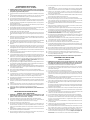 2
2
-
 3
3
-
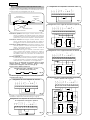 4
4
-
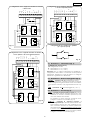 5
5
-
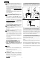 6
6
-
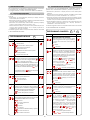 7
7
-
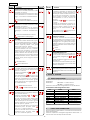 8
8
-
 9
9
-
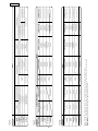 10
10
-
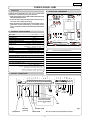 11
11
-
 12
12
-
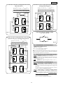 13
13
-
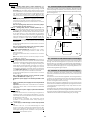 14
14
-
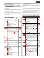 15
15
-
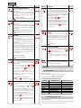 16
16
-
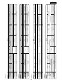 17
17
-
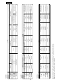 18
18
-
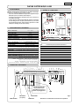 19
19
-
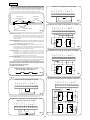 20
20
-
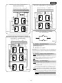 21
21
-
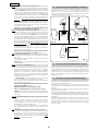 22
22
-
 23
23
-
 24
24
-
 25
25
-
 26
26
-
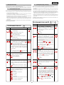 27
27
-
 28
28
-
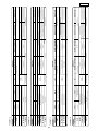 29
29
-
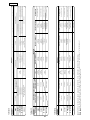 30
30
-
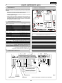 31
31
-
 32
32
-
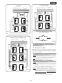 33
33
-
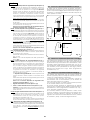 34
34
-
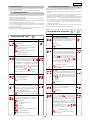 35
35
-
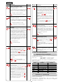 36
36
-
 37
37
-
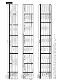 38
38
-
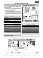 39
39
-
 40
40
-
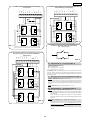 41
41
-
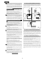 42
42
-
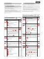 43
43
-
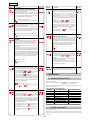 44
44
-
 45
45
-
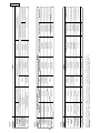 46
46
-
 47
47
-
 48
48


Genius JA383 Use And Installation Intructions
- Tipo
- Use And Installation Intructions
in altre lingue
- English: Genius JA383
- français: Genius JA383
- español: Genius JA383
- Deutsch: Genius JA383
Documenti correlati
-
Genius GEO 04 Istruzioni per l'uso
-
-
-
-
-
-
-
-
-
