Grace m906 Manuale del proprietario
- Categoria
- Apparecchiature musicali supplementari
- Tipo
- Manuale del proprietario

Rev B all contents © Grace Design/ Lunatec LLC
owner’s manual

grace design m906
owner’s manual
2
grace design m906
owner’s manual
3
Table of Contents
Welcome 2
Important Safety Information 3
m906 mainframe frontpanel 4
m906 Key Features 4
m906 mainframe rearpanel 5
m906 remote control unit 7
Unpacking and Installing your m906 System 9
Connecting the m906 10
System Connections 12
Operating the m906 14
Advanced Features: Accessing the Cal Modes 22
Cleaning and Maintenance 27
Cable and Connector Wiring Diagrams 28
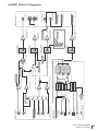
m906 Block Diagram 29
Specications 30
Warranty Information 32
Welcome
Thanks for purchasing the Grace Design m906 high delity 5.1 monitoring system. We build all our
products to be completely reliable and easy to use, so you can concentrate on producing great
sounding audio, not struggling with complicated equipment or difcult to use product manuals.
While the m906 has been designed to be straightforward to use, we do suggest that you spend a
little time familiarizing yourself with the features and operational functions that are contained in this
manual. Doing this now will likely make your experience with the m906 more enjoyable.
In the event that you encounter any technical or operational difculties with this or any Grace Design
product, please feel free to contact us at 303-443-7454. Our ofce hours are from 9 to 5, Monday
through Friday, MST. Or you can email your questions to: [email protected]om
Also, please remember to visit our website- www.gracedesign.com for the latest Grace Design
product information, owner’s manuals and technical documents.
Grace Design has been building audiophile quality products for the recording industry for over a
decade. The technology developed for the m906, and all of our products, has evolved through a
process of extensive listening, eld testing and careful renement.
Your new m906 system represents a combination of absolutely pristine audio performance, robust
mechanical construction and bombproof reliability.
Regardless of what type of work you do, your m906 will faithfully serve as an invisible link between
your source audio and your speaker systems. We sincerely hope our products help you achieve a new
level of excellence in your work! -The Grace Design Team

grace design m906
owner’s manual
2
grace design m906
owner’s manual
3
Important Safety Information
General
•Indoor use only
•Ordinary Protection: This equipment should not be exposed to dripping or splashing.
•Avoid placing objects lled with liquids, such as vases or glasses, on this
equipment.
•Class I Equipment (grounded type)
•Electrical rating: 100-120/220-240V~ 50-60Hz 25W
•Mains supply voltage uctuations are not to exceed ±10% of the nominal supply
voltage.
•Pollution Degree 2
•Installation (Overvoltage) Category II for transient overvoltages.
•Maximum Relative Humidity: <80%
•Operation temperature range: 10 °C to 40 °C
•Storage and transportation temperature range –40 °C to 70 °C
•Maximum altitude: 3000m (9843 ft)
•Equipment suitable for continuous operation
•Weight: 2.6kg (5.8lbs)
Safety Marking Symbols
CAUTION: READ ACCOMPANYING DOCUMENTS
This symbol, located on the equipment and in this manual, refers to important instructions. Read
this manual thoroughly before operating this equipment.
Service Information
The Grace Design m906 contains no user serviceable components. Contact Grace Design for repair
and upgrade information. In the event that your Grace Design m906 needs to be returned to the
factory, contact us for a return authorization number.
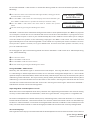
A
B
C

grace design m906
owner’s manual
4
grace design m906
owner’s manual
5
m906 Key Features
•Multiple 5.1 and stereo analog inputs
•24-bit/192kHz digital 5.1 and stereo inputs – AES3, S/PDIF, ADAT and TOSLINK formats
•s-Lock
tm
PLL (Phase Lock Loop) for ultra-low jitter sample clock regeneration
•Precision main and headphone level controls with a 100dB gain range in 0.5dB steps
•All controls built into an elegant, convenient desktop remote control unit
•All I/O and audio are routed in a 2U, 19” rack mount mainframe with an external 1U,
rack linear power supply
•Multiple speaker set selection – two surround/stereo sets and a third stereo set
•High current reference headphone amplier built in – one output on the remote
control unit and an additional output on the system mainframe
•Comprehensive system level calibration (inputs, outputs, inter-channel balance, dim)
•Individual channel solo/mute
•Balanced talkback microphone input with 48V phantom power with an activation
switch on remote and an additional external switch control jack
•Fixed level 5.1 DAC output for digital to analog transfers
•5 year limited warranty on parts and labor
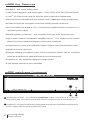
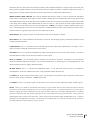
m906 mainframe frontpanel
power
headphone
GRACE DESIGN USA
A
B
HEADPHONE OUTPUT The mainframe headphone output is provided via a ” TRS (Tip,
Ring, Sleeve) jack. This output runs parallel with the headphone jack on the remote unit.
POWER LED The green POWER LED is illuminated when power is received from the external
power supply to the rear panel mounted DC input.
B
A

grace design m906
owner’s manual
4
grace design m906
owner’s manual
5
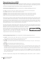
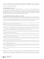
m906 mainframe rearpanel
TB MIC
5.1 CR OUT 2
5.1 CR OUT 1
5.1 INPUT 1
LS RS Sub
DC IN
5.1 DAC OUT
5.1 INPUT 2
REMOTE TB SW
2 CH 2
L R
GRACE DESIGN USA
2 CH 1
L
R
CUE IN
L
R
CUE OUT
L
R
CR OUT 2
L
R
CR OUT 1
L
R
Left RightCenter
DIGITAL INPUTS / SYNC
AES3
S/PDIF
AES3 x 4TOSADAT
THRU
GRACE DESIGN AT103 906 DAC
WORD CLOCK/
SUPERCLOCK
IN
1M
75
load
1
3
PUSH
2
1
3
PUSH
2
1
3
PUSH
2
1
3
PUSH
2
1
3
PUSH
2
1
3
PUSH
2
1
3
PUSH
2
1
3
PUSH
2
O TSRQ
L
M
G H
D
J
E I
A
C
F
B
K
N
P
U
5.1 DAC OUTPUT This female DB-25 connector supplies 5.1 xed level balanced DAC output
signals, wired to the Tascam DA-88 standard pinout.
5.1 CR OUT #2 This female DB-25 connector carries the balanced analog Control Room
Output #2 signals for connection to a 5.1 speaker system, wired to the Tascam DA-88
standard pinout.
5.1 CR OUT #1 This female DB-25 connector carries the balanced analog Control Room
Output #1 signals for connection to a 5.1 speaker system, wired to the Tascam DA-88
standard pinout.
DC IN This 6-pin male XLR DC input accepts the supplied cable from the m906’s external
power supply.
WORD CLOCK/SUPER CLOCK THRU This BNC connector is used to pass an external Word
Clock or Super Clock reference signal through to another digital device down stream of the
m906.
WORD CLOCK/SUPER CLOCK IN This BNC connector allows the m906 to receive an external
Word Clock or Super Clock source to be used as a reference for locking the m906’s internal
clocks.
WORD CLOCK TERMINATION SWITCH This switch is is used to properly terminate a
connection from an external clock reference source to the m906 Word or Super Clock
input.
ADAT INPUT This Lightpipe connector provides an 8-channel input interface from an ADAT
format digital source. 44.1kHz and 48kHz sample rates are supported.
AES3 STEREO INPUT This female XLR connector is used to receive a stereo AES3 format
digital signal.
(contunued)
C
F
G
H
D
E
I
B
A

grace design m906
owner’s manual
6
grace design m906
owner’s manual
7
S/PDIF STEREO INPUT This RCA jack input accepts a S/PDIF format digital stereo signal.
TOSLINK STEREO INPUT This optical connector accepts a TOSLINK format digital stereo
signal.
AES3 MULTI-CHANNEL INPUT This DB25 female connector accepts inputs from four AES3
format digital sources. The rst three AES3 inputs serve as the 5.1 digital input source
(channels 1 through 6) and the remaining pair is available as the second 2 CH AES3 input
(channels 7 and 8). Wired to the Tascam DA-88 standard pinout.
TB MIC INPUT This female XLR connector connects a talkback microphone to the m906 for
control room to studio communications. 48 Volt phantom power is provided.
5.1 UNBALANCED ANALOG INPUTS These six RCA jacks are used to input an unbalanced
(–10dBV) 5.1 source into the m906.
REMOTE CONNECTOR This female DB15 (high density) connector allows connection
between the m906 mainframe and the remote control unit via the supplied remote cable.
TB SW JACK This ” TRS talkback switch jack is for connecting an external switch used to
remotely activate the talkback microphone function.
CR OUT 1 and CR OUT 2 Analog, balanced stereo outputs for stereo control room output
sets #1 and #2. These connections are wired in parallel with the left and right outputs of the
corresponding 5.1 DB-25 control room outputs.
CUE OUT LEFT AND RIGHT An analog balanced stereo output for the CUE input signal. The
talkback microphone signal is summed into this output. This output can also be congured
to serve as a third stereo control room output pair.
CUE IN LEFT AND RIGHT This input is for connecting a stereo cue signal to the m906, which
can be routed to the stereo cue outputs for studio talent monitoring and be monitored
directly in the control room.
2 CH 1 and 2 CH 2 INPUT These are balanced analog stereo XLR inputs.
5.1 BALANCED ANALOG INPUTS This DB25 female connector accepts analog balanced
(+4dBu) signals for use as a 5.1 source input.
U
P
O
T
S
R
Q
J
N
L
M
K

grace design m906
owner’s manual
6
grace design m906
owner’s manual
7
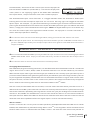
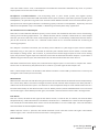
m906 remote control unit
channel
solo/mute
Left
Center Right
LS RS
Sub
input
5.1
AES3
5.1
ADAT
2ch
AES3
2ch
AES3
2ch
S/PDIF
2ch
ADAT/TOS
cue
5.1
BAL
5.1
UNBAL
2ch
BAL1
2ch
BAL2
1
2
talkback
input
GRACE DESIGN USA
main level / editheadphone level
calsel
dimmono mute
mon cue
(spkr 3)
spkr sel
analog
digital
solo/mute
A
B
C
F
G
E
H
D
L
J
I
N
M
P
K
O
R
Q
INPUT ANALOG SWITCHES This row of ve green LED illuminated switches is for selecting
between and monitoring any of the analog sources connected to the m906.
INPUT DIGITAL SWITCHES This row of six green LED illuminated switches is for selecting
between and monitoring any of the digital sources connected to the m906.
CHANNEL SOLO/MUTE SWITCHES These seven bi-colored switches are used to solo or mute
any individual channel being monitored by the m906. The rst six switches engage solo or
mute for the relevant channel, while the solo/mute switch is used to toggle between solo
or mute mode.
HEADPHONE LEVEL DISPLAY This blue, 3 digit headphone level display shows the current
relative headphone output level value based on the position of the headphone level rotary
encoder. The range of this display is 0 to 100dB.
HEADPHONE LEVEL ROTARY ENCODER This stepped rotary encoder controls the headphone
output level in .5dB increments. When monitoring multichannel sources, pushing this
encoder knob alows the headphone source channels to be selected.
MAIN LEVEL/EDIT DISPLAY This blue, 3 digit main level/edit display shows the current
relative main speaker output level values based on the position of the main level rotary
encoder. The range of this display is 0 to 100dB. The display also shows edit values when
the system is in CAL mode. (contunued)
A
C
B
F
D
E

grace design m906
owner’s manual
8
grace design m906
owner’s manual
9
MAIN LEVEL/EDIT ROTARY ENCODER This stepped rotary encoder controls the main speaker
output levels in .5dB increments. This encoder is also used to adjust level offset calibration
values when in CAL mode.
TALKBACK SWITCH This red illuminated momentary action switch engages the talkback
microphone circuit for as long as the switch is depressed. Releasing the switch disengages
talkback.
SPKR SEL SWITCH The speaker select switch is used to toggle between the available speaker
output sets. Each press of the switch lights the LED associated with each speaker set (1 or
2).
MONO SWITCH Pressing this green illuminated switch mono sums the stereo left and right
channels.
MUTE SWITCH The mute switch is used to fully mute all audio output from the m906. The
red switch LED illuminates when active.
DIM SWITCH Pressing this illuminated switch reduces the monitoring level of the currently
selected speaker output set by 20dB (this value can be edited in CAL mode). Pressing the
switch again returns the system to its normal output monitoring levels.
CAL SWITCH Pressing the CAL switch activates calibration mode on the m906. When CAL
mode is active, the red LED CAL switch will ash. CAL mode is exited by pressing the switch
again. Please refer to the ‘Accesing the Cal Modes’ chapter of this m anual for detailed
information about m906 system calibration.
MON > CUE SWITCH The MON > CUE switch is an illuminated switch used for routing the
selected stereo input source to the CUE output. In addition, this switch may be congured
to access a third stereo speaker pair output.
SEL SWITCH The SEL switch is used to select between Word Clock or Super Clock when an
external clock reference source is used.
SYSTEM LCD This backlit LCD shows various m906 status settings, such as the input source
selected, current sample rate, s-Lock
tm
state, clock source, etc…
HEADPHONE AMPLIFIER JACK This ” TRS headphone output jack is provided on the
remote control unit to access the integrated reference headphone amplier.
REMOTE CONNECTOR This female DB15 connector is used to supply the remote unit with
power, headphone signal and serial communication.
H
G
N
L
M
K
O
R
Q
P
J
I

grace design m906
owner’s manual
8
grace design m906
owner’s manual
9
Unpacking and Installing your m906 System
The m906 is shipped in two boxes. Box 1 contains:
•the m906 mainframe unit
•external power supply
•AC power cord
•6-pin XLR DC power cable
•small plastic bag containing four self-adhesive rubber feet
•warranty registration card
•some Grace Design literature for your reading pleasure
Box 2 contains:
•the remote control unit
•25’ remote cable
•remote unit height/angle adjustment legs
•small plastic bag containing four self-adhesive rubber feet
OPEN AND INSPECT THE BOXES
Open both shipping boxes, carefully remove the m906 system components and put them aside.
Before you go any further, check to make sure the above listed components are included with your
shipment. If you believe something is missing, contact your friendly Grace Design dealer and they will
make sure you’re taken care of.
SAVE YOUR BOXES!!
We strongly encourage you to save all of the boxes and shipping materials supplied with your m906.
They are specially designed to properly protect these valuable components, and in the unlikely event
that you need to return them for service, only these OEM shipping materials can ensure their safe
return to our factory.
REGISTER YOUR UNIT
Also, we strongly urge you to register your unit with Grace Design. We provide a limited 5 year warranty
on all of our products, but if you don’t register your system it’s hard for us to help you if and when help
becomes necessary. So please take a few minutes to complete the enclosed warranty registration card
and mail it in, or simply go to the warranty registration form on our web site. Thank you!

grace design m906
owner’s manual
10
grace design m906
owner’s manual
11
Okay, let’s get started in making the necessary connections to get your m906 up and running. First
thing to do is mount the mainframe unit in a rack. If you’re not rack mounting the unit, you should
attach the supplied rubber feet on each corner of the mainframe so you won’t scratch it or the surface
you place it on.
One thing you will want to consider is where to position the external power supply. The supplied cable
to connect the power supply to the mainframe is 8’ (2.8m) long. The power supply can be mounted
in a standard rack tray (not supplied) via the 10/32” mounting thread located towards the rear of the
supply on the bottom panel.
Power Connections
The Disconnect Device for the m906 system is the Mains plug or the Appliance Coupler
on the power supply cord. The Disconnect Device must remain accessible and operable.
The power supply cord supplied with the m906 must be connected to a mains outlet
with a protective earthing connection.
Grounding Options
In certain installations, it may be desirable to separate the m906’s signal ground from the power supply
chassis and earth grounds. Noise inducing ground loops can be broken while retaining the safety
feature of the grounded AC cable. The m906 should not be operated with a ground lift or “cheater”
plug on the AC power cord. Simply set the AUDIO GND toggle switch on the rear panel of the power
supply unit to the desired setting (ISO or EARTH).
Check Line Voltage Settings
The power supply unit has been set from the factory to operate at the voltage required for your part of
the world. However, it’s important to double-check this in order to ensure no damage will come to the
unit if power is applied while the setting is incorrect.
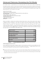
Line Voltage Selector
To change the line voltage, use a small screwdriver to pry open the voltage select door. Carefully
remove the voltage select cam and re-insert it with the desired voltage showing. Use table 1 below for
voltage settings and fuse values.
Table 1 Voltage and Fuse information.
CAM SETTING LINE VOLTAGE FUSE VALUE
100V~ 100V~ 250V~ T 750mA L
120V~ 120V~ 250V~ T 750mA L
220V~ 220V~ 250V~ T 500mA L
220V~ 230V~ 250V~ T 500mA L
240V~ 240V~ 250V~ T 500mA L
Connecting the m906

grace design m906
owner’s manual
10
grace design m906
owner’s manual
11
DC Power Cord
The rst connection to make is from the power supply unit to the main chassis with the supplied 6 pin
XLR DC power cord. Important: the DC power cable and the remote cable should be connected BEFORE
the AC power is turned on. This prevents incorrect power sequencing which can potentially cause damage
to the m906’s audio circuits.
AC Power Cord
Now connect the supplied AC cord to the power supply and then to an AC outlet with the supplied AC
cable. For safety, it is recommended that the cable be connected to a grounded outlet.
Connecting the Remote Control Unit to the Mainframe
The m906 remote control unit connects to the system mainframe via a supplied, high quality 25’ cable.
Each end of the cable terminates in a male DB15 connector. This cable provides RS-422 serial data,
power and headphone signal to the remote.
Make the connection by securing the remote cable to the remote control unit and then attaching the
other end to the mainframe. Both ends of the cable are identical so it doesn’t matter which end you
connect to the remote or mainframe. NOTE: The HD15 connector on each end of the remote cable does
not use a “VGA” computer monitor pinout (see the cable wiring diagram section of this manual). If you need
a cable longer than 25’, do NOT go to your local electronic supply store to purchase an off-the-shelf VGA
extension. It won’t work. Instead, please call us at 303-443-7454 and we’ll help you out.
Attaching the Tilt Adjustment Legs to the Remote Control Unit
The m906 remote control unit can be placed directly on a at surface or can be tilted forward with the
pair of supplied legs. If you intend to place the remote on a at surface, you should rst attach the self-
adhesive rubber feet (supplied) to each corner of the bottom of the chassis. This will prevent the unit
from scratching your surface and from the bottom panel of the remote from being scratched. The legs
for the remote are threaded on one end and screw into the threaded holes at the rear corners of the
bottom panel. The remote tilt angle can be adjusted slightly by screwing the legs in or out.
Power Sequence
Before powering up your m906, make sure your monitor speakers or power amps connected to your
monitors are turned OFF, which will prevent any “popping” in your speaker systems. Once the m906 and
the rest of your audio system are powered up, turn on the power to your speakers. When powering
down, we recommend that you rst power off your speaker system and then power down the m906.
It should also be noted that while the power sequence will not damage headphones connected to the
m906, you should NOT be wearing them when power is applied or turned off.

grace design m906
owner’s manual
12
grace design m906
owner’s manual
13
5.1 DAC OUT The xed level balanced DAC output connector is wired to the Tascam DA-88 standard.
With CAL mode, the output level can be adjusted in 0.5dB steps. The factory default cal setting output
Voltage is +16dBu for 0dBFS.
5.1 CR OUT 1 and 5.1 CR OUT 2 These are the multichannel control room outputs which are wired to
the Tascam standard pinout and carry the balanced Left, Center, Right, Left Surround, Right Surround
and Sub signals. The signal level on these connectors is controlled by the main level/edit encoder on
the remote control.
REMOTE CONNECTOR Connects the m906 main chassis unit to the remote control unit. This DB15
connector carries RS244 serial data, DC power and headphone signals. The m906 ships with a 25’ cable.
While the serial data can travel several hundred feet we do not recommend cables longer than 50’
for headphone use. Be sure to use the supplied 15 pin cable and not an off the shelf computer video
cable. If you need a longer cable contact your Grace Design dealer or call us directly.
TB SW JACK The talkback switch input allows the connection of an external switch, such as a
footswitch, for remotely activating the talkback mic input on the m906. The input is a TRS jack and is
used with a “normally open” switching device. Note that when using this jack the talkback function can
be activated at the remote control unit and the remote switch.
DC IN This 6 pin XLR connector carries the DC power from the power supply unit. +24V, -24V, +8V and
+48V are present. Connect this DC power cord BEFORE turning on the AC power at the power supply
unit.
CR OUT 1 and CR OUT 2 These are the stereo XLR balanced control room outputs. They are wired
in parallel with the Left and Right signals from the corresponding 5.1 CR OUT #1 and #2 DB-25
connectors. Standard balanced XLR cables can be used with these outputs (pin 1 shield, pin 2 positive,
pin 3 negative).
CUE OUT This is the stereo XLR balanced CUE output, which outputs the signal present on the CUE
INPUT connectors. Typically this output would be wired to your studio’s headphone cue system or it
can double as a third speaker output. Standard XLR balanced cables can be used with this output.
2 CH 1 and 2 CH 2 INPUTS These are stereo XLR balanced inputs. Standard XLR balanced cables can
be used with these inputs (pin 1 shield, pin 2 positive, pin 3 negative).
WORD CLOCK/SUPER CLOCK THRU This BNC connector allows you to pass the clock received at the
Word Clock/Superclock input to other digital devices downstream of the m906. The output is buffered
and is designed to drive a 75 Ohm line.
WORD CLOCK/SUPER CLOCK IN The m906 can accept an external Word Clock or Super Clock signal
from an external clock generating unit. This might be a stand-alone clock source or via, for example,
the Word Clock output from your digital audio workstation. It should be noted that referencing the
m906 from an external Word Clock is not necessary for the unit to function properly as the m906 will
also function quite nicely by stripping embedded clock data from a connected digital audio source.
System Connections

grace design m906
owner’s manual
12
grace design m906
owner’s manual
13
However, you may have your entire digital audio system referenced from a single master clock that you
feel particularly good about, hence the ability for the m906 to receive and lock itself to this clock. A
high quality 75 Ohm cable should be used for word clock or Superclock connections.
WORD CLOCK LOAD SWITCH The switch labeled 1M Ohm/75 Ohm is used to terminate the Word
Clock input. If the Word Clock signal in your studio is being daisy-chained from unit to unit, (including
the m906) you’ll want to set the switch to 1M Ohm, which is essentially an unloaded setting. If the m906
is the only device being clock referenced (or the last unit in a daisy-chain of other high impedance
units), you’ll want to select the 75 Ohm load position. NOTE: Selecting the 75 Ohm load position when
there is already another device on the line that has a 75 Ohm load will create a total load of 37 Ohms, which
will attenuate the signal to a point where the m906 will not lock.
ADAT INPUT This input accepts standard ADAT multi-channel optical cables.
AES3 INPUT This input conforms to the AES3 standard. Use of high quality 110 Ohm balanced cable
is highly recommended.
S/PDIF INPUT This is a standard coaxial stereo digital input. The input impedance is 75 Ohms. Use a
quality 75 Ohm cable for connections to this input.
TOS INPUT This is a standard stereo optical input connector for use with consumer devices. Standard
TOSLINK optical cable can be used to connect to this input.
AES3 x 4 INPUT This 8 channel input conforms to the AES3 standard. Channels 1-6 are used for
surround monitoring while channels 7-8 can be monitored as a stereo signal. Use of high quality 110
Ohm balanced cable is highly recommended.
TB MIC INPUT This is a standard microphone input. It can be used with dynamic or condenser
microphones. Use CAL mode to turn the +48V phantom power on and off.
5.1 INPUT 2 These unbalanced input jacks are designed to interface with consumer DVD/SACD
players. They accept a nominal –10dBV input level.
5.1 INPUT 1 This 5.1 channel input is wired to Tascam standard and accepts balanced +4dBu signals.
NOTE: You’ve just made a substantial investment in your m906 and it’s likely that you have a decent
investment in the other components you use in your audio system. As a professional we’re sure this goes
without saying, but now is denitely not the time to spare expense on the audio cabling you’ll use to hook
up your m906. After all, the m906 is going to be the heart of your listening environment, where you’ll be
making all of your critical sonic decisions. Cable and connector quality make a large difference – both for
analog as well as digital connections, so the better the cabling you use with your m906 system, the better
overall performance you’ll achieve in your system.

grace design m906
owner’s manual
14
grace design m906
owner’s manual
15
Okay, you’ve rack mounted your m906, attached the remote control unit, connected the power
supply and have made all of your audio connections. Now the fun begins! The following sections
will take you through the operational details of your m906 monitoring system.
Selecting an Analog Input Source The m906 provides the following analog input sources:
• 5.1 bal balanced 5.1 format input (DB25 connector wired to the Tascam standard pinout)
• 5.1 unbal unbalanced 5.1 format input via RCA connectors.
• 2ch bal 1 balanced stereo input (XLR connectors wired pin 2 hot, pin 3 cold and pin 1 ground)
• 2ch bal 2 balanced stereo input (XLR connectors wired pin 2 hot, pin 3 cold and pin 1 ground)
• cue balanced stereo input (XLR connectors wired pin 2 hot, pin 3 cold and pin 1 ground)
Pressing the cue switch activates the stereo cue input source for monitoring. The cue inputs on the
rear of the m906 will normally be fed by a stereo pair output from your digital audio workstation or
console that has been setup to provide a cue mix to talent in the studio. The cue input switch allows
you to monitor this cue mix in the control room. Also related to the cue function is the MON > CUE
and Talkback features, w hich are discussed later in the manual.
To select the desired analog source input, simply press the switch that corresponds to the source
you’d like to monitor. Each time you press a switch to select a new source to monitor, the new source
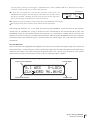
becomes active and the source switch LED illuminates. The name
of the current input will be displayed on line one of the SYSTEM
LCD (screenshot 1). Line two will display DAC status (which is still
supplying signal to the FIXED DAC OUTPUTS). DAC Input source,
sample rate and s-Lock status will be displayed.
Selecting a Digital Input Source The m906 provides the following digital input sources:
• 5.1 AES3 5.1 format input using 3 AES3 signals on a DB-25 connector wired to the Tascam standard for 8
channel digital I/O. Input channels 1-6 are monitored on this input.
• 5.1 ADAT 5.1 format input using ADAT light pipe channels 1-6
• 2ch AES3 two channel AES3 input on an XLR connector wired wired pin 2 hot, pin 3 cold and pin 1
ground
• 2ch AES3 two channel AES3 input on DB-25 channels 7-8
• 2ch S/PDIF two channel input on an RCA coaxial connector.
• 2ch ADAT/TOS two channel input derived from channels 7-8 of the ADAT optical input connector or left
and right channels from the TOSLINK optical input. (Out of the box, this switch selects the ADAT format as
the default choice. To change the current source selection, simply press this switch again. When this occurs,
the newly selected format will be displayed in the system LCD window.) NOTE: The two channel ADAT format
source is derived from channels 7 and 8 from the ADAT input on the rear panel. It cannot be sourced from any
other pair of ADAT channels.
To select a digital input, simply press the corresponding input switch (AES3 1, AES3 2, S/PDIF or
Operating the m906
screenshot 1
analog input selected, DAC status

grace design m906
owner’s manual
14
grace design m906
owner’s manual
15
TOSLINK/ADAT ). The name of the current input will be displayed on
line one of the SYSTEM LCD (screenshot 2). Line two will display DAC
status (which is still supplying signal to the FIXED DAC OUTPUTS).
DAC Input source, sample rate and s-Lock status will be displayed.
The TOSLINK/ADAT input switch functions as a toggle between either the TOSLINK or ADAT input.
Pressing once activates the optical input that was last used. Pressing again will toggle to the other
optical input. For example, say you were monitoring a TOSLINK signal and then switched to AES3 1,
pressing the TOSLINK/ADAT switch would activate the TOSLINK input once again. To monitor the ADAT
source, simply press the TOSLINK/ADAT switch again. NOTE: The digital ADAT input is derived from any
one of the four channel pairs of an eight channel ADAT interface. The input pair is selected in CAL mode. To
choose ADAT input pair do the following:
Press the CAL switch. The switch LED will begin to ash, letting you know that CAL mode is now active.
Press the optical input switch. The LCD display will indicate weather you are in TOSLINK or ADAT mode. If
you are in TOSLINK input mode, press the optical input switch once again to reach ADAT mode. The menu is
stepped as follows:
TOSLINK INPUT OFFSET
è
ADAT INPUT OFFSET
è
ADAT SOURCE PAIR SELECT
è
Once in ADAT INPUT OFFSET MODE, pressing the OPTICAL input switch one more time will bring up the ADAT
SOURCE PAIR SELECT menu. Simply use the main/edit rotary encoder to choose the desired input source
pair.
Press the CAL switch to exit CAL mode and return to normal operation.
Changing the Clock Source
The m906 DAC (Digital to Analog Converter) can be referenced to the embedded clock of a connected
digital source such as AES3, ADAT, S/PDIF or TOSLINK. The DAC can also be clocked by an external
Word Clock or Super Clock signal. The clock type you choose to use is entirely up to you. You may like a
particular external Word Clock generating device that you reference your entire digital audio system to
or you might feel completely comfortable with an embedded clock from a digital audio stream. From
our point of view, it matters little as our s-Lock
tm
PLL (Phase Lock Loop) will automatically be applied
once it detects the incoming clock source. Read more about s-Lock
tm
below.
The SEL switch, located below the LCD window, is used to select the clock source you’d like to use as a
reference for the m906 system. The LCD will show the currently selected source. If you’d like to change
the current selection, repeatedly pressing the SEL switch will cycle you through the available choices
which are: AES, WORD and SUPERCLOCK. The LCD text will ash if there is no valid clock available at
the input selected. When the m906 has locked to the selected clock source the text in the LCD will be
solid. The clock source preference for each digital input is saved in non volitile memory.
About s-Lock
tm
s-Lock
tm
is our new PLL circuitry that has been specically developed for both the m906 and its stereo
brother, the m904. The truly wonderful thing about s-Lock
tm
is that regardless of the condition of the
external clock used as a reference for the m906, s-Lock
tm
will take this clock source and provide an
digital input select/ DAC status
screenshot 2

grace design m906
owner’s manual
16
grace design m906
owner’s manual
17
extremely stable and ultra-low jitter clock to run the DACs. The goal, of course, is pristine audio. We
think you’re going to love s-Lock
tm
. Here’s a bit more detail on how this works.
s-Lock
tm
is a crystal-based PLL used for regenerating the incoming digital clock. The crystals used have
extremely low intrinsic jitter and are capable of locking to sample rates of up to 192kHz. When the
digital input selected for the DAC is active, the s-Lock
tm
circuitry automatically captures the incoming
recovered clock from AES3, S/PDIF, TOSLINK, or ADAT or from an external Word Clock or Super Clock.
Once phase-lock with the incoming signal has been achieved, the DACs, which have been running
off the original clock, are switched to run off the ultra-low jitter s-Lock
tm
system clock. If at any time
s-Lock
tm
is lost or not achieved, the DAC’s are run off the original clock. The s-Lock
tm
system can
effectively lock to input sample rates of 44.1kHz or 48kHz +/- 10Hz, 88.2kHz or 96kHz +/- 20Hz and
176.4kHz or 192kHz +/- 40Hz.
If the incoming digital audio signal or word clock frequency is outside of these tolerances or if an invalid
clock source is selected the s-Lock
tm
circuit will not lock and the s-Lock
tm
indicator on the system LCD
not be visible. Even if the s-Lock
tm
does not achieve lock, the digital audio receiver circuits in the m906
can achieve excellent recovered clock jitter performance.
Selecting Speaker Outputs The m906 provides the following speaker output sets:
• 5.1 CR OUT 1 (balanced via female DB-25 connector)
• 5.1 CR OUT 2 (balanced via female DB-25 connector)
• Stereo CR OUT 1 (balanced via two male XLR connectors wired pin 2 hot, pin 3 cold and pin 1 ground)
• Stereo CR OUT 2 (balanced via two male XLR connectors wired pin 2 hot, pin 3 cold and pin 1 ground)
• Optionally, a third stereo pair via CUE OUT (balanced via two male XLR connectors wired pin 2 hot, pin 3 cold
and pin 1 ground)
The SPKR SEL switch, located directly above the TALKBACK switch, is used to cycle between available
speaker output sets. The conguration of the speaker output set used is based on the current input
selected, i.e. if you have a 5.1 input source selected, this audio will be routed out via one of the two
available 5.1 control room outputs. If you have a stereo input source, this will be routed to the left and
right Control Room output XLRs, as well as the left and right connections on a DB-25 Control Room
output. Similarly, with a 5.1 source, left and right will be present on both the XLRs and the DB-25s.
The currently selected output set number is indicated by illuminating the relevant LED to the left of
the SPKR SEL switch. To toggle through the available output sets, simply press the SPKR SEL switch.
For example, if speaker output number 1 is currently active, pressing the SPKR SEL switch will change
this to speaker output number 2. Pressing the switch again will toggle the selection back to speaker
output number 1.
Using MON > CUE (spkr 3) as a Third Stereo Speaker Output
In most situations, having access to two sets of stereo control room outputs will be adequate. This
will allow, for instance, CR OUT 1 to feed your main stereo monitors and CR OUT 2 to feed a near-eld
pair. However, if you nd yourself in need of a third stereo monitoring conguration, we’ve got you
covered.

grace design m906
owner’s manual
16
grace design m906
owner’s manual
17
To activate the MON > CUE switch as a control for routing audio to a third set of stereo speakers, do the
following:
Press the CAL switch. The switch LED will begin to ash, letting you know
that CAL mode is now active.
Press the MON > CUE switch. The LCD display will indicate whether you
are in MON > CUE mode or in Speaker #3 mode (screenshots 3 & 4).
Press the MON > CUE switch one more time to activate this special
mode.
Exit CAL mode by pressing the ashing CAL switch.
The MON > CUE switch has now been congured to select a third speaker output set. Note: the physical
stereo outputs used for this are the CUE OUT XLRs on the rear of the m906 mainframe. Cycling between the
rst two speaker outputs is done as you would normally do, via the SPKR SEL switch. When you’re ready to
select the third stereo speaker set for monitoring, simply press the MON > CUE switch. The switch LED will
light solid and you’ll now be monitoring audio sent to a third stereo speaker pair via the CUE OUT’s. To return
to the previous speaker selection (1 or 2), press MON>CUE. To return to the other speaker selection (1 or 2),
press the SPKR SEL button.
To disengage this special monitoring mode and return the MON > CUE switch to its default operating
state, do the following:
Press the CAL switch.
Press the MON > CUE switch.
Press the MON > CUE switch once more
Exit CAL mode by pressing the ashing CAL switch.
Using the MON > CUE Feature
Normally, the CUE INPUT signal is routed to the CUE output. Pressing the MON > CUE switch when
it’s controlling its default operational mode, i.e. has not been congured to operate as a third stereo
speaker output as outlined above, routes the currently selected input source (L+R channels) that you’re
monitoring to the CUE OUTs. This is particularly handy when you’d like to send the stereo source you’re
monitoring in the control room out to the talent in the studio. Pressing the switch for the rst time
activates this mode and illuminates the switch LED. Pressing the switch again deactivates the MON >
CUE feature and the switch LED extinguishes.
Adjusting Main and Headphone Levels
Both the main and headphone level rotary controls use stepped digital encoders that control analog
circuitry in the m906. Both are attenuators, rather than gain controls. Using them is straightforward.
To increase headphone or control room (main) monitoring levels, rotate the encoders in a clockwise
fashion. To decrease levels, rotate the encoders in a counter-clockwise motion. Levels can be altered up
or down in .5dB increments and channel tracking between channels is 0.05dB. In CAL mode (discussed
later), the main level encoder is used to change parameters for the function currently being edited.
The Level Displays
The large blue LED displays located to the left of the headphone and main level encoders show relative
speaker 3 mode, global offset
screenshot 4
cue mode, global level
screenshot 3

grace design m906
owner’s manual
18
grace design m906
owner’s manual
19
level values in dB. The range is 0 to 100 with 0 being full-off and 100 equaling unity gain, or full-on
level. In CAL mode (discussed later), the LED display labeled main level/edit is used to display edit
parameters as they’re being changed.
Using the Headphone Outputs
The m906 provides two reference headphone outputs, via ” TRS jacks wired as left channel to Tip,
right channel to Ring and ground to Sleeve. One is located on the front panel of the system mainframe
and the other is on the rear of the remote control unit. Both may be used simultaneously. The m906
headphone amplier is based on our model 901 reference headphone amp except that the m906
version will allow you to listen to digital audio sources up to 192kHz!
Using the Headphone Outputs to Monitor 5.1 Channels
When you have a 5.1 source selected for monitoring, the headphone outputs will normally only allow
you to hear the left and right channels from this 5.1 source. There may be times, however, when you
may want to listen (through headphones) to other channel combinations of the 5.1 source. We’ve
included a nice little feature that allows you to do this. Here’s how this special mode works:
First, select a 5.1 source input; analog or digital. Please note that this special 5.1 headphone mode cannot be
made active if your current source selection is stereo.
Press down on the headphone level rotary encoder switch. You’ll feel a click when you do this, and yes, there’s
a switch under there. Hold it down for about 4 seconds. This action will turn the 5.1 headphone feature on.
Notice that the Left and Right channel solo/mute switch LEDs are now illuminated. This indicates which pair
of channels is currently being fed to the headphone outputs. You’ll also notice that the solo/mute master
mode switch LED is extinguished. This is because this switch is not used in this mode.
The channel switches in this mode, unlike normal solo/mute mode, act in an interlocking fashion. This means
that once you select a new pair of 5.1 channels to monitor through your headphones, the previous channel
selections are automatically turned off.
Channel pairs that are available for monitoring in this mode include left/right, left surround/right surround
and center/sub. Please note that you cannot monitor individual channels or other pair combinations other
than which are listed above. (continued)
To select the Left Surround/Right Surround pair, press either the LS or RS switch. The surround channels
will now be sent to the headphone outputs, the corresponding channel switch LEDs will light solid and the
previous channel pair selection will become inactive.
To select the Center/Sub channel pair, press either the Center or Sub switch. These channels will now be sent
to the headphone outputs, the corresponding channel switch LEDs will light solid and the previous channel
pair selection will become inactive.
To return to the Left/Right channel pair, press either the Left or Right switch. These channels will now be sent
to the headphone outputs, the corresponding channel switch LEDs will light solid and the previous channel
pair selection will become inactive.
To exit the 5.1 headphone mode and return to the m906’s normal operating state, press the headphone
encoder switch.
Note: If you’ve selected a 5.1 source, are currently in the 5.1 headphone mode and inadvertently select a
stereo input source, this mode will automatically become inactive and the m906 will return to it’s normal
operational state. You can, however, select different 5.1 sources while in this mode. CAL mode is not operable

grace design m906
owner’s manual
18
grace design m906
owner’s manual
19
when this mode is active. Also, it should also be noted that this mode does NOT affect any of the 5.1 speaker
output paths nor the xed level DAC output.
Headphone recommendations: Like everything else in your audio system, the higher quality
headphones you use with the m906, the better results you’ll achieve. If you don’t yet own a great set of
headphones, do yourself a big favor and audition some different models that will work well for you in
your particular working environment. Performing quality control via headphones, especially with the
reference headphone amp in the m906, is something we think you’ll really appreciate.
The Fixed Level 5.1 DAC Output
The DACs in the m906 are reference quality circuits which are suitable for the most critical monitoring,
mixing and mastering applications. As a bonus feature, we’ve included a xed level 5.1 DAC output
that lets you access the DACs with a xed output level. This is an extremely useful feature which allows
you to, for instance, send out a 5.1 channel audio stream to a 6 channel recorder for mastering or
archiving purposes.
This output is fed from whatever you currently have selected as your digital input source. Another
beautiful thing is that you can continue to monitor your control room source while a transfer from
this output is being made. For instance, if you leave the current digital input to listen to an analog
input, the previous digital input will continue to be sent to the xed level DAC outputs. If you select a
different digital source input, the xed level DAC will then be fed from that new source.
The lower line of the LCD display will indicate which digital input is active and its sample rate. The s-
Lock status is indicated by the presence of an asterisk (*) to the right of the sample rate.
The 5.1 DAC output level is set to 0dB as the default value on a new m906 system but this can easily be
changed in CAL mode (discussed later).
Mono Mode
Mono mode is used to sum the left and right channels of a stereo source to check for mono compatibility.
This switch only affects the Left and Right channels of the control room outputs but does provide a
mono version of whatever inputs are selected in the headphone outputs. The mono mode switch is
located immediately to the left of the dim switch. When pressed, mono mode becomes active and the
switch LED lights solid. When pressed again, the mode is exited and the switch LED is extinguished.
Dim Mode
The dim switch, located to the right of the mono switch, is used to dim, or reduce, the control room
output levels by a xed dB amount. The default value for this is -20dB but this value can be changed in
CAL mode (discussed below). Dim values can be set between -5 to -35 in 5dB steps. Dim will not affect
the audio feed to the headphone outputs.
When the dim switch is pressed, dim mode becomes active and the switch LED lights solid. When
pressed again, dim is exited and the switch LED is extinguished.
Mute All Mode

grace design m906
owner’s manual
20
grace design m906
owner’s manual
21
The mute switch is located to the immediate right of the dim switch. When this switch is pressed, all
audio output is muted, or cut, from the control room monitors. Note that mute will not affect the audio
feed to the headphone outputs.
When the mute switch is pressed, mute mode becomes active and the switch LED lights solid. When
pressed again, mute is exited and the switch LED is extinguished.
Channel Solo/Mute
The m906 provides the ability to solo or mute any one channel or any combination of channels in either
a stereo or 5.1 monitoring setup. Need to listen to the surround channels plus the center channel only?
No problem. Wish you could mute the sub? You got it. Channel solo/mute mode is an easy way to
accomplish these types of monitoring tasks.
The channel solo/mute function is provided via a row of seven bi-color, illuminated switches located
directly below the input digital switch row on the remote control unit. Operating channel solo/mute
couldn’t be easier…
First, select the mode of operation via the solo/mute switch. This switch is the last switch in the row and by
default it will be lit green, which indicates that solo mode is currently active. If you’d like to change this to
mute mode, simply press this switch and the switch led will light red, which now indicates that you’re in mute
mode.
To select a channel to solo or mute, simply press the relevant channel switch. When you do this, the associated
switch LED will light solid. Again, green shows solo while red indicates mute. These switches are additive, which
simply means that you can add channels by pressing the relevant channel switches without disengaging the
previous selections. For instance, if you’re in solo mode and want to solo the left surround channel, (LS) right
surround (RS) and sub, you simply press each of these channels’ switches. If you set the solo/mute master
mode switch to ‘mute’ at this point, these selected channels will be muted. To clear selected channels, simply
press each of them again, which will also extinguish the switch LEDs.
Using the Talkback Feature
The m906 provides a balanced talkback microphone input on the rear panel of the mainframe unit via
a female XLR connector. This talkback mic input is essentially a single channel from our model 801R
preamp. Not bad, huh?
After you’ve plugged in a talkback mic, you can set the gain for the mic preamp and turn on 48v
phantom power, if needed. By the way, when you rst power-up a new m906, the talkback mic preamp
gain will be set to +30dB and 48v will be set to ‘off’. To change the gain and 48V phantom settings:
Press the CAL switch. The switch LED ashes, which indicates you’re now
in CAL mode.
Press the TALKBACK switch. Once you do this, the main level/edit LED
display will show the current mic amp gain level in dB and the LCD screen
will read ‘set preamp gain’ (screenshot 5).
To increase the mic amp gain, rotate the main level encoder in a clockwise direction. As you do this, you’ll see
talkback mic amp gain setting
screenshot 5
La pagina si sta caricando...
La pagina si sta caricando...
La pagina si sta caricando...
La pagina si sta caricando...
La pagina si sta caricando...
La pagina si sta caricando...
La pagina si sta caricando...
La pagina si sta caricando...
La pagina si sta caricando...
La pagina si sta caricando...
La pagina si sta caricando...
La pagina si sta caricando...
-
 1
1
-
 2
2
-
 3
3
-
 4
4
-
 5
5
-
 6
6
-
 7
7
-
 8
8
-
 9
9
-
 10
10
-
 11
11
-
 12
12
-
 13
13
-
 14
14
-
 15
15
-
 16
16
-
 17
17
-
 18
18
-
 19
19
-
 20
20
-
 21
21
-
 22
22
-
 23
23
-
 24
24
-
 25
25
-
 26
26
-
 27
27
-
 28
28
-
 29
29
-
 30
30
-
 31
31
-
 32
32


Grace m906 Manuale del proprietario
- Categoria
- Apparecchiature musicali supplementari
- Tipo
- Manuale del proprietario
in altre lingue
- English: Grace m906 Owner's manual
Altri documenti
-
M-Audio Octane Guida utente
-
NGS NETSTEREO Scheda dati
-
Crown Macro-Reference Manuale utente
-
Yamaha PM4000 Manuale utente
-
Aria A1260R Instructions Manual
-
-
-
-
-