Risco BWare BUS DT AM G3 Manuale utente
- Categoria
- Rilevatori di movimento
- Tipo
- Manuale utente

x 3
x 1
Model:
RK515DTBG3
BWare BUS DT AM G3
EN50131-2-4, PD6662 :2010,
Grade 3, EC2
IT
EN
FR
PR
ES
Introduction and Features
The BWare BUS DT AM detector is a motion detector designed for
installation as an addressable detector on the RISCO BUS,
incorporating both Anti-Mask and Anti-Cloak™ Technologies (ACT™).
• MW K-Band and PIR technologies
• Anti-Cloak Technology (ACT™)
• Green Line™ for disabling the MW during disarm
• Active IR Anti-Mask
• Cover and wall/corner tampers
• Corridor and Curtain lenses (optional)
• Remote Control & Diagnostics
• 15m (90') coverage
Introduction et caractéristiques
Le détecteur BWare BUS DT est un détecteur de mouvement destiné
à être installé en tant que détecteur adressable sur le BUS RISCO,
incorporant les technologies Anti-Masque et Anti-Cloak™ (ACT™).
• Technologies hyperfréquence Bande K et IR Passif
• Technologie Anti-Cloak™ (ACT™)
• Anti-masque actif à IR
• Green Line™ pour désactiver l’hyperfréquence durant le
désarmement
• Autoprotection à l’ouverture et l’arrachement mur/angle
• Lentilles couloir et rideau (optionnelles)
• Contrôle et diagnostique à distance
• Couverture 15m (90')
Introduzione e caratteristiche
BWare BUS DT AM è un rivelatore di movimento a doppia tecnologia
indirizzato compatibile con il BUS RISCO che include un sistema di
Anti-Mascheramento e la tecnologia Anti-Cloak™ (ACT™).
• Tecnologia a microonde (MW in banda K) e infrarosso
passivo (PIR)
• Tecnologia Anti-Cloak (ACT™)
• Funzione “Green Line” per disabilitare le emissioni della
sezione microonda a sistema disinserito
• Anti-Mask con IR attivo
• Tamper contro l’apertura e la rimozione
• Lenti a Tenda e Corridoio (opzionali)
• Diagnostica e Controllo Remoto
• Modelli da 15m (90')
Introducción y características
El detector BWare BUS DT AM es un detector de movimiento
diseñado para su instalación como detector direccionable en el BUS
de RISCO, que incorpora las tecnologías de Anti-Enmascaramiento y
Anti-Cloak™ (ACT™).
• Doble tecnología MW (Banda K) y PIR
• Tecnología Anti-Cloak (ACT™) para detectar intrusos camuflados
• GreenLine™ para deshabilitar el MW cuando el sistema
esté desarmado
• Anti-Enmascaramiento por IR Activo
• Tamper de tapa y pared
• Lentes de Pasillo y Cortina (opcionales)
• Control y Diagnósticos Remotos
• Cobertura 15m (90')
Introdução e características
O BWare BUS, detector AM de dupla tecnologia, é um detector de
movimento projetado para ser instalado como detector endereçável
ao RISCO Bus, incorporando tecnologia tanto Anti-Mask quanto Anti-
Cloak ™.
• Tecnologia Anti-Camuflagem (ACT ™)
• Tecnologia GreenLine - Desativa MW (Microondas),quando o
sistema é desativado.
• Anti-Máscara por Infra Vermelho Ativo.
• Lentes de longo alcance e Cortina (opcional)
• Controle e diagnóstico remoto
• Modelo 15m (90')
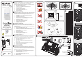
64mm (2.51")
120mm (4.72")
44mm (1.73")
9-16VDC
100gr. (3.5oz.)
mA
12mA at 12VDC (typical)
34mA at 12VDC (max.)
-20° to 55°C ( -4° to 131°F)
Humidity of 85 ±5 percent at a
temperature of 30 ±2°C (86 ±4°F).
BUS
COM
RED
BLK
YEL
+ 12 -
GRN
Z1
LONG
15m (50’)
SHORT
6m (20’)
LONG
SHORT
RISCO BUS
12VDC
MIN
MAX
N/C
N/O
4.7K
N/C N/O EOL
NO
N/C FAULT/ AM Contact
TEOL
N/C Tamper Switch
N/C Alarm Relay
4.7K
6.8K
12K
DEOL
4.7K
6.8K
N/C Tamper
Switch
N/C Alarm Relay
1
2
4
5
3
ID 1 2 3 4 5
01 OFF OFF OFF OFF OFF
02 ON OFF OFF OFF OFF
03 OFF ON OFF OFF OFF
04 ON ON OFF OFF OFF
05 OFF OFF ON OFF OFF
06 ON OFF ON OFF OFF
07 OFF ON ON OFF OFF
08 ON ON ON OFF OFF
09 OFF OFF OFF ON OFF
10 ON OFF OFF ON OFF
11 OFF ON OFF ON OFF
12 ON ON OFF ON OFF
13 OFF OFF ON ON OFF
14 ON OFF ON ON OFF
15 OFF ON ON ON OFF
16 ON ON ON ON OFF
17 OFF OFF OFF OFF ON
18 ON OFF OFF OFF ON
19 OFF ON OFF OFF ON
20 ON ON OFF OFF ON
21 OFF OFF ON OFF ON
22 ON OFF ON OFF ON
23 OFF ON ON OFF ON
24 ON ON ON OFF ON
25 OFF OFF OFF ON ON
26 ON OFF OFF ON ON
27 OFF ON OFF ON ON
28 ON ON OFF ON ON
29 OFF OFF ON ON ON
30 ON OFF ON ON ON
31 OFF ON ON ON ON
32 ON ON ON ON ON
O
N
12
3
4
5
BUS ADDRESS
2.1m-2.7m
(6'11"-8'10")

3RL0025V (Corridor)
Walk Test Test Sensore Prueba de detección Test de Marche Prova de Moviento
EN FRIT PRES
System Programming:
1. Add/delete a BWare BUS detector
• Installer menu [7] Accessories / Install > [1] Add Delete Module > [9] More.. > [5] BUS Zone.
• Select ID (as defined by the Dip switches) and define type as BDTG3.
2. Assign the BWare BUS detector to a Zone
• Installer menu [2] Zones > [1] One by One > Select Zone.
• Under Termination select > [5] BUS Zone.
• Select the BUS zone number to assign to the programmed zone.
3. Program the zone input on the BWare BUS
• Installer menu [2] Zones > [1] One by One > Select Zone.
• Under Termination select from options [07] to [11].
• Press [#]. Select the BUS zone that the input zone belongs to.
4. Configure the BWare BUS detector parameters.
• Installer menu select [2] Zones > [0] Miscellaneous > [3] BUS Zone Parameters. Refer to System Installation Manual.
Programmazione Sistema:
ProSYS: 1. Aggiungi/cancella un rivelatore BUS BWare
• Menù Tecnico [7] Accessori > [1] Agg./Canc.Modulo > [9] Continua.. > [5] Zone BUS
• Selezionare il numero ID (come impostato dai microinterrutori) e definire il tipo come BDTG3
2. Assegnazione del rivelatore BUS BWare ad una Zona
• Menù Tecnico [2] Zone > [1] Una per Una > Selezionare il numero di zona
• Raggiunta l'opzione Terminazione selezionare > [5] Zona BUS
• Selezionare il numero ID della zona BUS da assegnare alla zona che si sta programmando
3. Programmazione dell'ingresso di zona aggiuntivo sul rivelatore BUS BWare
• Menù Tecnico [2] Zone > [1] Una per Una > Selezionare il numero di zona
• Raggiunta l'opzione Terminazione selezionare una delle opzioni da [07] a [11]
• Premere [#]. Selezionare il numero ID della zona BUS che fa riferimento all'ingresso di zona che si sta programmando
4. Configurazione dei parametri del rivelatore BUS Bware
• Nel Menù Tecnico selezionare [2] Zone > [0] Varie > [3] Parametri Zone BUS > Selezionare il numero di zona al
quale è stato assegnato il rivelatore. Fare riferimento al Manuale Tecnico della centrale per i parametri del rivelatore
LightSYS: 1. Aggiungi/cancella un rivelatore BUS Bware
• Menù Tecnico [7] Configurazione > [1] Accessori BUS > [2] Configurazione Manuale > [9] Zone-BUS
• Selezionare l’identificativo ID (come impostato dai microinterruttori) e definire il Tipo come BDTG3
3. Programmare l’ingresso di zona del rivelatore BWare BUS
• Una volta completata l’operazione descritta al punto 1, la centrale automaticamente chiederà se aggiungere alla
zona sucessiva l’ingresso di zona aggiuntivo del rivelatore
4. Programmare i parametri del rivelatore
• Menù Tecnico [2] Zone > [1] Parametri > [2] Per Parametro > [7] Avanzati > [4] Zone BUS > Selezionare il numero di
zona al quale è stato assegnato il rivelatore. Fare riferimento al Manuale Tecnico della centrale per i parametri del
rivelatore
Programación Sistema:
1. Añadir/Borrar un detector BWare BUS
• Menú Instalador > [7] Accesorios > [1] Agregar/Borrar Módulo > [9] Más... > [5] Zonas BUS
• Seleccione el ID (según se haya definido con los microinterruptores DIP) y defina el tipo como BDTG3.
2. Asignar el detector BWare BUS a una Zona
• Menú Instalador > [2] Zonas > [1] Una a Una > Seleccione la Zona
• En el apartado Terminación, seleccione la opción [05] Zona BUS.
• Seleccione el ID del detector BUS que se va a asignar a la zona programada.
3. Programar la entrada de zona adicional del BWare BUS
• Menú Instalador > [2] Zonas > [1] Una a Una > Seleccione la Zona.
• En el apartado Terminación, seleccione una de las opciones de la [07] a la [11].
• Presione [#]. Seleccione el ID del detector BUS al que pertenece la entrada de zona.
4. Configuración de los parámetros del detector BWare BUS.
• Menú Instalador > [2] Zonas > [0] Varios > [3] Parámetros Zona BUS. Consulte el manual de instalación del sistema
para la configuración de los parámetros del detector BUS.
PR
Programmation Système:
1. Ajout/Supp détecteur BWare BUS
• Menu Installateur [7] Accessoires / Installation > [1] Ajout/Supp Module > [9] Plus. > [5] Zone BUS.
• Sélectionner l’ID (défini par les Dip switches) et définir le type en BDTG3.
2. Assigner le détecteur BWare BUS à une Zone
• Menu Installateur [2] Zones > [1] Une par Une > Sélectionner Zone.
• Dans Nature sélectionner > [5] BUS Zone.
• Sélectionner le numéro de la zone BUS à assigner à la zone programmée.
3. Programmer la zone d’entrée du BWare BUS
• Menu Installateur [2] Zones > [1] Une par Une > Sélectionner Zone.
• Dans Nature sélectionner les options [07] à [11].
• Appuyer sur [#].Sélectionner le numéro de la zone BUS à assigner à la zone programmée.
4. Configurer les paramètres du détecteur BWare BUS.
• Menu Installateur sélectionner [2] Zones > [0] Divers > [3] Param Zone BUS. Reportez-vous au manuel d'installation
du système pour les paramètres des détecteurs BUS.
Programação da Sistema:
1. Adicionar/Apagar um detector BWare BUS
• Menu do instalador [7] Acessórios > [1] Adicionar/Apagar módulo > [9] Mais.. > [5] Zonas de BUS.
• Selecionar ID (como definido nos Dipswitches) e definir como o tipo BDTG3.
2. Alocar o BWare BUS à uma zona
• Menu do Instalador [2] Zonas > [1] Uma a Uma > Selecionar Zona.
• No menu de Terminação selecione > [5] Zona de BUS.
• Selecione o número da zona de BUS para alocar a zona programada.
3. Programação da entrada de zona do BWare BUS
• Menu do instalador [2] Zonas > [1] Uma a uma > Selecionar Zona.
• No menu de terminação escolha uma das opções de [07] até [11].
• Apertar [#]. Escolher a zona de BUS que a entrada de zona pertence.
4. Configurar os parâmetros do detector BWare BUS.
• Selecionar o menu do instalador [2] Zonas > [0] Diversos > [3] Parâmetros de Zonas de BUS.
© RISCO Group 12/2013 5IN2110
Poland
Tel: +48-22-500-28-40
support-pl@riscogroup.com
United Kingdom
Tel: +44-161-655-5500
support-uk@riscogroup.com
Spain
Tel: +34-91-490-2133
support-es@riscogroup.com
Belgium (Benelux)
Tel: +32-2522-7622
support-be@riscogroup.com
Brazil
Tel: +55-11-3661-8767
support-br@riscogroup.com
Contacting RISCO Group
RISCO Group is committed to customer service and product support. You can contact us through our
website www.riscogroup.com or as follows:
China (Shanghai)
Tel: +86-21-52-39-0066
support-cn@riscogroup.com
Italy
Tel: +39-02-66590054
support-it@riscogroup.com
France
Tel: +33-164-73-28-50
support-fr@riscogroup.com
USA
Tel: +1-631-719-4400
support-usa@riscogroup.com
Australia
Tel: + 1-800-991-542
support-au@riscogroup.com
China (Shenzhen)
Tel: +86-755-82789285
support-cn@riscogroup.com
Israel
Tel: +972-3963-7777
support@riscogroup.com
= ON
C
D
A B
= 2 Min
2 Min. (Max)
6
7
RISCO Group Limited Warranty
RISCO Ltd., its subsidiaries and affiliates (the "Seller") warrants its products to be free from defects in materials
and workmanship under normal use for 24 months from the date of production.
Because the Seller does not install or connect the product, and because the product may be used in conjunction
with products not manufactured by the Seller, the Seller cannot guarantee the performance of the security
system which uses this product.
The Seller's obligation and liability under this warranty is expressly limited to repairing and replacing, at the
Seller's discretion, within a reasonable time after the date of delivery, any product not meeting these
specifications.
The Seller makes no other warranty, expressed or implied, and makes no warranty of merchantability or of
fitness for any particular purpose.
Under no circumstances should the Seller be liable for any consequential or incidental damages for breach of
this or any other warranty, expressed or implied, or upon any other basis of liability whatsoever.
The Seller's obligation under this warranty shall not include any transportation charges or costs of installation or
any liability for direct, indirect, or consequential damages or delay.
The Seller does not warrant that the product may not be compromised or circumvented; that the product will
prevent any personal injury or property loss by burglary, robbery, fire or otherwise; or that the product will in all
cases provide adequate warning or protection.
The buyer/customer understands that a correctly installed and maintained alarm may only reduce the risk of
burglary, robbery or fire without warning, but is not an insurance or a guarantee that such an event will not
occur or that there will be no personal injury or property loss as a result thereof.
Consequently the Seller shall have no liability for any personal injury, property damage or loss based on a claim
that the product fails to give warning.
However, if the Seller is held liable, whether directly or indirectly, for any loss or damage arising under this
limited warranty or otherwise, regardless of cause or origin, the Seller's maximum liability shall not exceed the
purchase price of the product, which shall be a complete and exclusive remedy for the Seller.
No employee or representative of the Seller is authorized to change this warranty in any way or grant any other
warranty.
Batteries installed in or used with the products are explicitly excluded from this or any other warranty. Seller
gives no warranty whatsoever as to batteries and buyer's only remedy (if any) shall be in accordance with the
warranty provided (if and to the extent provided) by the manufacturers of batteries.
Yellow
LED
LED Display
State
On
Description
PIR Detection
Flashing
Trouble in PIR channel
Green
On MW Detection
Flashing
Trouble in MW channel
Blue
On
Alarm
Flashing
Communication Trouble
Rapid Flashing
Anti-Masking detection
All
LEDs
Flashing
(consecutively)
At power-up, the LEDs will flash consecutively
until the end of the warm-up period (2-3
minutes). At the end of the warm-up period the
BLUE LED will continue to flash until the end of
AM calibration.
EN
Amarillo
LED
Indicación de los LEDs
Estado
Encendido
Descripción
Detección PIR
Parpadeando Problema en el canal PIR
Verde
Encendido
Detección MW
Parpadeando Problema en el canal MW
Azul
Encendido Indicación de ALARMA
Parpadeando Problema de comunicación
Parpadeo Rápido Detección Anti-Enmascaramiento
Todos
los
LEDs
Parpadeando
(consecutiva mente)
Al dar alimentación, los LEDs parpadearán
consecutivamente hasta que finalice el
periodo de calentamiento (2-3 minutos). Al
finalizar el periodo de calentamiento, el LED
AZUL seguirá parpadeando hasta que termine
la calibración del AM.
ES
Giallo
LED
Indicatori LED
Stato
Illuminato
Descrizione
Rilevazione del canale all’infrarosso passivo (PIR)
Lampeggiante Anomalia del canale PIR
Verde
Illuminato
Rilevazione del canale a microonda (MW)
Lampeggiante Anomalia del canale MW
Blu
Illuminato ALLARME
Lampeggiante Problema di comunicazione
Lampeggiante
Rapido
Anomalia / Rilevazione circuito Anti-Mask
Tutti i
LED
Lampeggiante
(consecutivamente)
All’alimentazione tutti i LED lampeggiano in
sequenza fino alla fine del periodo di
preriscaldamento (2-3 minuti). Alla fine del
periodo di preriscaldamento il LED BLU
continuerà a lampeggiare fino alla fine della
fase di inizializzazione del canale Anti-Mask.
IT
Jaune
LED
Affichage LED
Etat
Allumée
Description
Détection IRP
Clignotante
Défaut canal IRP
Verte
Allumée
Détection HF
Clignotante Défaut canal HF
Bleu
Allumée
Alarme
Clignotante
rapide
Détection Anti-Masque
Totalité
LED’s
Clignotante
(consécutivement)
Au démarrage, les voyants LED
clignotent successivement jusqu'à la
fin de la période d'échauffement (2-3
minutes). A la fin de la période
d'échauffement la LED bleue
continuera à clignoter jusqu'à la fin de
l'étalonnage AM.
FR
Amarelo
LED
Visualizacão dos LEDs
Estado
Aceso
Descricao
Detecção de Infravelmenho Passivo
Piscado Problema no canal Infravelmenho Passivo
Verde
Aceso
Detecção no Microondas
Piscado Problema no canal Microondas
Azul
Aceso
ALARME
Piscado
Problema de comunicação
Piscado Rápido
Falha/ Detecção Anti Máscara.
Todos os
LEDs
Piscado
(sucessivamante)
Ao conectar, os LEDs piscarão
consecutivamente até o final do período de
aquecimento (2-3minutos). Ao final do
período de aquecimento, o LED AZUL
continuará piscando até o final da iniciação
do AM.
PR
RL0004V (Wide Angle)
Wide Angle – Side View
Wide Angle – Top View
MW Sensitivity Po rtata Microonda
Alcance del Microondas
Sensibilité MW Alcance de microondas
EN
FR
IT
PR
ES
Corridor – Side View
Corridor – Top View
3RL0024V (Curtain)
Curtain – Top View
Curtain – Side View
Corridor – Side View
FCC modular approval
Contains FCC ID UXS-IPM165F BWare RK515DTG3 FCC Compliance Section:
FCC Part 15 Note:
This equipment has been tested and found to comply with the limits for a Class B digital device, pursuant to Part 15 of the FCC
rules. These limits are designed to provide reasonable protection against harmful interference in a residential installation. This
equipment generates, uses and can radiate radio frequency energy and, if not installed and used in accordance with the
instructions, may cause harmful interference to radio communications. However, there is no guarantee that interference will not
occur in a particular installation. If this equipment does cause harmful interference to radio or television reception, which can be
determined by turning the equipment off and on, the user is encouraged to try to correct the interference by one or more of the
follow ing me a sure s:
• Reorient or relocate the receiving antenna.
• Increase the separation between the equipment and receiver.
• Connect the equipment to an outlet on a circuit different from that to which the
receiver is connected.
• Consult the dealer or an experienced radio/TV technician.
FCC Warning:
The manufacturer is not responsible for any radio or TV interference caused by unauthorized modifications to this equipment.
Such modifications could void the user's authority to operate the equipment.
FR
ES
IT
EN
-
 1
1
-
 2
2


Risco BWare BUS DT AM G3 Manuale utente
- Categoria
- Rilevatori di movimento
- Tipo
- Manuale utente
in altre lingue
- English: Risco BWare BUS DT AM G3 User manual
Documenti correlati
-
Risco Bware BUS DT G2 Guida Rapida
-
-
-
Risco Industrial LuNAR RK200DTG3 Guida d'installazione
-
-
-
-
 RISCO Group WatchOUT Guida d'installazione
-
-
Ris iWISE QUAD AM Grade 3 Manuale utente
