Monacor ESUB-6W/WS Installation Instructions Manual
- Tipo
- Installation Instructions Manual

ELECTRONICS FOR SPECIALISTS ELECTRONICS FOR SPECIALISTS ELECTRONICS FOR SPECIALISTS ELECTRONICS FOR SPECIALISTS
INSTALLATIONSANLEITUNG
INSTALLATION INSTRUCTIONS
NOTICE D’INSTALLATION
ISTRUZIONI PER L’INSTALLAZIONE
ESUB-6W/SW
Bestell-Nr. • Order No. 25.9920
ESUB-6W/ WS
Bestell-Nr. • Order No. 25.9930
ELA-Subwoofer
für die Wandmontage
PA Subwoofer
for Wall Installation

2
+
LEFT
− +
RIGHT
−
SATELLITE OUTPUT
+
LEFT
− +
RIGHT
−
DIRECT INPUT
COM COM
70V/100V
INPUT
100V 70V
60W 30W
30W 15W
15W 7,5W
MODE
INPUT
SELECT
70V/100V
DIRECT
STEREO
MONO
3
4
2
1
5
➀
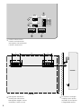
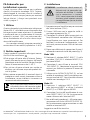
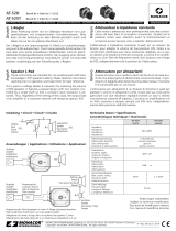
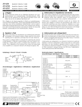
Schalter und Anschlüsse
Switches and connections
Interrupteurs et branchements
Controlli e connessioni
➁
Montage der Wandhalter
Installing the wall brackets
Montage des supports muraux
Installazioni e staffe a muro
➂
Lautsprecher einhängen
Hanging up the speaker
Suspendre le haut-parleur
Fissaggio dello speaker
ESUB-6W/…
ESUB-6W/…
72 214 72
93257

3
ELECTRONICS FOR SPECIALISTS ELECTRONICS FOR SPECIALISTS ELECTRONICS FOR SPECIALISTS ELECTRONICS FOR SPECIALISTS
Deutsch ..........Seite 4
English ...........Page 5
Français ..........Page 6
Italiano...........Pagina 7
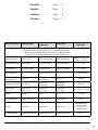
Technische Daten Specifications
Caractéristiques
techniques
Dati tecnici
ESUB-6W/…
Doppelt ventilierter Bandpass-Subwoofer mit Doppelschwingspule
Band-pass subwoofer with dual voice coil and double ventilation
Subwoofer passe-bande à double ventilation avec double bobine
Subwoofer passa banda doppia bobina doppia ventilazione
Nennbelastbarkeit Power rating Puissance nominale Range di potenza
100 V: 60 / 30 / 15 W
4 Ω: 2 × 60 W
Belastbarkeit, gesamt Music power Puissance totale Potenza musicale 2 × 125 W
Frequenzbereich Frequency range Bande passante Range di frequenza 50 – 200 Hz
Kennschalldruck SPL Pression sonore SPL 87 dB (1 W/1 m)
Maximaler
Nennschalldruck
Max. SPL
Pression sonore
nominale max.
Max. SPL
108 dB
Lautsprechergröße Speaker size
Dimensions
haut-parleur
Dimensioni
altparlante
16 cm (6”)
Abmessungen
(B × H × T)
Dimensions
(W × H × D)
Dimensions
(l × h × p)
Dimensioni
(l × h × p)
450 × 350 ×
180 mm
Gewicht Weight Poids Peso 12,25 kg
Gehäusematerial Cabinet material Matériau caisse Materiale box MDF
Anschluss Connection Branchement Connessioni
Schraubklemmen
screw terminals
bornes à vis
terminali a vite
Einsatztemperatur Ambient temperature Température fonc. Range temperatura
0 – 40 °C

4
Deutsch
English
English Page
Français
Français Page
Italiano
Italiano Pagina
Español
Español Página
Nederlands
Nederlands Pagina
Polski
Polski Strona
Deutsch
Deutsch Seite
ELA-Subwoofer
fürdieWandmontage
Diese Anleitung richtet sich an Installateure mit
Fachkenntnissen in der 100-V-Beschallungstech-
nik. Bitte lesen Sie die Anleitung vor der Instal-
lation gründlich durch und heben Sie sie für ein
späteres Nachlesen auf. Auf der Seite 2 finden
Sie alle zugehörigen Zeichnungen.
1 Verwendungsmöglichkeiten
Dieser Subwoofer ist speziell für den Einsatz in
ELA-Beschallungsanlagen konzipiert und dient zur
Bassunterstützung bei neuen und bestehenden
Installationen. Er ist mit einem Übertrager für den
Betrieb in 100-V-Anlagen ausgestattet, kann aber
auch direkt an einen niederohmigen Verstärker-
ausgang angeschlossen werden.
Über die integrierte Frequenzweiche können
Satellitenlautsprecher (Impedanz 4 – 8 Ω) direkt an
den ESUB-6W angeschlossen werden.
2 Wichtige Hinweise
Der Lautsprecher entspricht allen relevanten
Richtlinien der EU und trägt deshalb das -Zei-
chen.
•
Verwenden Sie den Lautsprecher nur im In-
nenbereich. Schützen Sie ihn vor Tropf- und
Spritzwasser sowie vor hoher Luftfeuchtigkeit.
Der zulässige Einsatztemperaturbereich beträgt
0 – 40 °C.
•
Verwenden Sie zum Reinigen nur ein trockenes,
weiches Tuch, niemals Wasser oder Chemika-
lien.
•
Wird der Lautsprecher zweckentfremdet, nicht
sicher montiert, falsch installiert oder überlas-
tet, kann keine Haftung für daraus resultie-
rende Sach- oder Personenschäden und keine
Garantie für den Lautsprecher übernommen
werden.
Soll der Lautsprecher endgültig aus dem
Betrieb genommen werden, übergeben
Sie ihn zur umweltgerechten Entsor-
gung einem örtlichen Recyclingbetrieb.
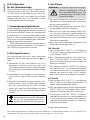
3 Installation
WARNUNG
Im Betrieb liegt berührungsge-
fährliche Spannung bis 100 V an
der Lautsprecherleitung an. Die
Installation darf nur durch Fach-
personal erfolgen.
1) Vor der Installation des Subwoofers den ELA-
Verstärker ausschalten, damit die Lautsprecher-
leitung spannungsfrei ist!
2) Die beiliegenden Wandhalter nach der Abb. 2
an geeigneter Stelle festschrauben.
3) Beim Anschluss der Lautsprecher darauf ach-
ten, dass diese alle gleich gepolt werden und
der Verstärker nicht überlastet wird. Die grü-
nen Klemmenblöcke lassen sich zur leichteren
Handhabung abziehen.
4) Nach dem Anschließen den Subwoofer in die
Wandhalter einhängen (Abb. 3).
100-V-Betrieb
5) Den Schalter INPUT SELECT (1) in die Position
70V/100V stellen und den Schalter MODE (2)
in die Position MONO.
6)
Das Lautsprecherkabel an den Klemmen-
block 70V/100V INPUT (3) anschließen. Die
gewünschte Nennleistung durch Auswahl der
Klemmen festlegen.
7) Am Ausgang SATELLITE OUTPUT (5) kann an
den Klemmen LEFT ein Satellitenlautsprecher
mit einer Impedanz von 4 – 8 Ω angeschlossen
werden. Der Anschluss eines 100-V-Lautspre-
chers hieran ist in keiner Betriebsart möglich.
4-Ω-Betrieb
5) Den Schalter INPUT SELECT (1) in die Position
DIRECT stellen und mit dem Schalter MODE (2)
Stereo- oder Monobetrieb wählen.
6)
Den Verstärkerausgang an den Klemmenblock
DIRECT INPUT (4) anschließen. Beim Mono-
betrieb nur die Klemmen LEFT verwenden.
7)
Am Ausgang SATELLITE OUTPUT (5) können
Satellitenlautsprecher mit einer Impedanz von
4 – 8 Ω angeschlossen werden. Beim Monobe-
trieb den Satellitenlautsprecher an die Klem-
men LEFT anschließen.
Diese Bedienungsanleitung ist urheberrechtlich für MONACOR
®
INTERNATIONAL GmbH & Co. KG geschützt. Eine
Reproduktion für eigene kommerzielle Zwecke – auch auszugsweise – ist untersagt.
Änderungen vorbehalten.

5
English
Italiano
Italiano Pagina
Español
Español Página
Nederlands
Nederlands Pagina
PA Subwoofer for Wall Installation
These instructions are intended for installers with
specific knowledge of sound reproduction using
100 V technology. Please read the instructions
carefully prior to installation and keep them for
later reference. The corresponding drawings can
be found on page 2.
1 Applications
This subwoofer is specially designed for PA sys-
tems. It is used as a bass support in new or exist-
ing installations. The subwoofer is provided with
a transformer for operation in 100 V systems, but
it can also be directly connected to a low-imped-
ance amplifier output.
The integrated crossover network allows
direct connection of satellite speakers (imped-
ance: 4 – 8 Ω) to ESUB-6W.
2 Important Notes
The speaker corresponds to all relevant directives
of the EU and is therefore marked with .
•
The speaker is suitable for indoor use only.
Protect it against dripping water, splash water
and high air humidity. The admissible ambient
temperature range is 0 – 40 °C.
•
For cleaning only use a dry, soft cloth; never
use water or chemicals.
•
No guarantee claims for the speaker and no
liability for any resulting personal damage or
material damage will be accepted if the speaker
is used for other purposes than originally in-
tended, if it is not safely or correctly installed,
or if it is overloaded.
If the speaker is to be put out of oper-
ation definitively, take it to a local recy-
cling plant for a disposal which is not
harmful to the environment.
3 Installation
WARNING During operation, there is a haz-
ard of contact with a dangerous
voltage of up to 100 V at the
speaker cable. Installation must
be made by skilled personnel only.
1) Before installing the subwoofer, switch off the
PA amplifier so that the speaker cable will not
carry any voltage!
2)
Use screws to fasten the wall brackets provided
at a suitable place (fig. 2).
3)
When connecting the speakers, make sure
that all of them have the same polarity and
that the amplifier is not overloaded. To make
handling easier, the green terminal blocks can
be disconnected from their plug-in connec
-
tions.
4)
After connecting, hang the subwoofer onto
the wall brackets (fig. 3).
100 V mode
5)
Set the switch INPUT SELECT (1) to the position
70V/100V and set the switch MODE (2) to the
position MONO.
6)
Connect the speaker cable to the terminal
block 70V/100V INPUT (3). Select the corre-
sponding terminals to define the desired power
rating.
7)
At the output SATELLITE OUTPUT (5), a satellite
speaker with an impedance of 4 – 8 Ω can be
connected to the terminals LEFT. It is not pos-
sible to connect a 100 V speaker to this output
in any operating mode.
4 Ω mode
5)
Set the switch INPUT SELECT (1) to the position
DIRECT and use the switch MODE (2) to select
mono or stereo mode.
6) Connect the amplifier output to the terminal
block DIRECT INPUT (4). For mono mode, only
use the terminals LEFT.
7)
Satellite speakers with an impedance of 4 – 8 Ω
can be connected to the output SATELLITE
OUTPUT (5). For mono mode, connect the
satellite speaker to the terminals LEFT.
Subject to technical modification.
English
English Page
All rights reserved by MONACOR
®
INTERNATIONAL GmbH & Co. KG. No part of this instruction manual may be
reproduced in any form or by any means for any commercial use.

6
Français
Deutsch
Deutsch Seite
English
English Page
Italiano
Italiano Pagina
Español
Español Página
Nederlands
Nederlands Pagina
Polski
Polski Strona
Subwoofer Public Adress pour
montage mural
Cette notice d’utilisation s’adresse aux instal-
lateurs ayant des connaissances techniques en
sonorisation 100 V. Veuillez lire la présente notice
avec attention avant l’installation et conservez-la
pour pouvoir, si besoin, vous y reporter ultérieu-
rement. Vous trouverez sur la page 2 tous les
schémas correspondants.
1 Possibilités d’utilisation
Ce subwoofer est spécialement conçu pour une
utilisation dans des installations de sonorisation
Public Adress et permet d’améliorer la restitu-
tion des graves dans des installations nouvelles
et existantes. Il est doté d’un transformateur pour
fonctionnement dans des installations 100 V mais
il peut également être branché directement à une
sortie amplificateur basse impédance.
Via le filtre de fréquences intégré, il est pos-
sible de relier des satellites (impédance 4 – 8 Ω)
directement au ESUB-6W.
2 Conseils importants d’utilisation
Le haut-parleur répond à toutes les directives né-
cessaires de l’Union européenne et porte donc le
symbole .
•
Le haut-parleur n’est conçu que pour une
utilisation en intérieur. Protégez-le des écla-
boussures, de tout type de projections d’eau et
d’une humidité d’air élevée. La plage de tem-
pérature ambiante admissible est de 0 – 40 °C.
•
Pour le nettoyage, utilisez uniquement un
chiffon sec et doux, en aucun cas de produits
chimiques ou d’eau.
•
Nous déclinons toute responsabilité en cas de
dommages matériels ou corporels résultants si
le haut-parleur est utilisé dans un but autre que
celui pour lequel il a été conçu, s’il n’est pas
monté de manière sûre, s’il n’est pas correcte-
ment installé ou s’il y a surcharge ; en outre,
la garantie deviendrait caduque.
Lorsque le haut-parleur est définitive-
ment retiré du service, vous devez le
déposer dans une usine de recyclage
adaptée pour contribuer à son élimina-
tion non polluante.
3 Installation
AVERTISSEMENT
Pendant le fonctionnement,
une tension de contact dan-
gereuse jusqu’à 100 V est pré-
sente sur le câble haut-parleur.
Seul un personnel qualifié peut
effectuer l’installation.
1)
Avant d’installer le subwoofer, éteignez l’ampli-
ficateur Public Adress pour que le câble haut-
parleur ne soit pas porteur de tension.
2)
Vissez les supports muraux livrés à l’endroit
voulu selon le schéma 2.
3)
Lorsque vous branchez les haut-parleurs, assu-
rez-vous qu’ils aient tous la même polarité et
que l’amplificateur ne soit pas en surcharge. Il
est possible de retirer les borniers à pince verts
pour une meilleure manipulation.
4)
Une fois le subwoofer relié, accrochez le
subwoofer sur les supports muraux (schéma 3).
Mode 100 V
5) Mettez l’interrupteur INPUT SELECT (1) sur la
position 70V/100V et l’interrupteur MODE (2)
sur la position MONO.
6)
Reliez le câble haut-parleur au bornier 70V/
100V INPUT (3). Définissez la puissance no-
minale souhaitée en sélectionnant les bornes.
7) Sur la sortie SATELLITE OUTPUT (5), il est pos-
sible de relier aux bornes LEFT un satellite avec
une impédance de 4 – 8 Ω. Il n’est pas possible
de brancher un haut-parleur 100 V dans n’im-
porte quel mode de fonctionnement.
Mode 4 Ω
5)
Mettez l’interrupteur INPUT SELECT (1) sur la
position DIRECT et avec l’interrupteur MODE (2),
sélectionnez le fonctionnement stéréo ou mono.
6)
Reliez la sortie amplificateur au bornier DIRECT
INPUT (4). En mode mono, utilisez uniquement
les bornes LEFT.
7)
Il est possible de relier à la sortie SATELLITE
OUTPUT (5) des satellites avec une impédance
de 4 – 8 Ω. En mode mono, reliez le satellite
aux bornes LEFT.
Tout droit de modification réservé.
CARTONS ET EMBALLAGE
PAPIER À TRIER
Français
Français Page
Notice d’utilisation protégée par le copyright de MONACOR
®
INTERNATIONAL GmbH & Co. KG. Toute reproduction
même partielle à des fins commerciales est interdite.

7
Italiano
Español
Español Página
Nederlands
Nederlands Pagina
PA Subwoofer per
installazioniaparete
Queste istruzioni sono indicate per installatori
specifici di impianti a tecnologia 100 V. Cortese-
mente leggere le istruzioni prima di installare il
prodotto e tenerle sempre pronte per eventuali
letture ulteriori. I disegni corrispondenti sono
visibili in pagina 2.
1 Utilizzo
Questo subwoofer è particolarmente indicato per
impianti PA. E’ utilizzabile come rinforzo alle note
basse per impianti nuovi ed esistenti. Il subwoofer
è predisposto con un trasformatore di linea per
operare in impianti 100 V, ma può essere con-
nesso direttamente ad un’uscita a bassa impe-
denza dell’amplificatore.
Un crossover network integrato permette la
connessione di box satelliti (impedenza: 4 – 8 Ω).
2 Notizie importanti
Questo speaker è rispondenti alle vigenti norma-
tive EU ed ha marchiatura .
•
Può essere utilizzato solo all’interno. Proteg-
gere il diffusore da spruzzi di acqua, dall’acqua
gocciolante e da alta umidità. Range di tempe-
ratura di lavoro ammessa da 0 – 40 °C.
•
Per pulizia utilizzare salviette non umide ne
abrasive, mai utilizzare acqua e /o prodotti chi-
mici di pulizia.
•
Non saremo responsabili di eventuali danni al
prodotto o a terzi causati da erroneo utilizzo e
installazione, se non istallato in sicurezza o se
sovraccaricato elettricamente.
Per lo smaltimento del prodotto non più
utilizzabile riferirsi alle normative vigenti
per lo smaltimento corretto dei rifiuti.
3 Installazione
ATTENZIONE
L’installazione dovrà essere ef-
fettuata solo da personale spe
-
cializzato ed abilitato. Si ricorda
che le connessioni in impianti
100 V sono interessate da media
tensione quindi operare sempre
con amplificatore spento, durante
l’installazione
1)
Spegnere sempre l’amplificatore per non avere
cavi sotto tensione (100 V).
2)
Fissare il diffusore con le apposite staffe in
posizione appropriata (fig. 2).
3)
Controllare la polarità delle connessioni con
l’amplificatore e controllare che il diffusore e
l’amplificatore non siano sovraccaricati. Per
facilitare l’uso durante il collegamento, i mor-
setti verdi possono essere sfilati dai loro con-
nettori.
4) Dopo aver effettuato le connessioni fissare il
subwoofer traamite le staffe alla parete (fig. 3).
Modo 100 V
5) Predisponi il selettore INPUT SELECT (1) nella
posizione 70V/100V il selettore MODE (2) in
posizione MONO.
6)
Connettere il cavo di linea ai terminali 70V/
100V INPUT (3). Selezionare le apposite con-
nessioni per definire la potenza di lavoro del
subwoofer.
7) Utilizzo uscite SATELLITE OUTPUT (5), un box
satellite di impedenza 4 o 8 Ω potrà essere con-
nesso ai terminali LEFT. Non è possible utilizzare
satellite con tecnologia 100 V.
Modo 4 Ω
5)
Predisponi il selettore INPUT SELECT (1)
nella posizione DIRECT e utilizza il selettore
MODE(2) su STEREO oppure MONO.
6) Connettere l’uscita dell’amplificatore al mor-
setto DIRECT INPUT (4). Per funzionamento
mono utilizzare solo i terminali LEFT.
7)
Box satellite ad impedenza 4 – 8 Ω potranno es-
sere connessi all’uscita SATELLITE OUTPUT(5).
Per funzionamento mono connettere un solo
satellite ai terminali LEFT.
Soggetto a modifiche tecniche.
Italiano
Italiano Pagina
La MONACOR
®
INTERNATIONAL GmbH & Co. KG si riserva ogni diritto di elaborazione in qualsiasi forma delle presenti
istruzioni per l’uso. La riproduzione – anche parziale – per propri scopi commerciali è vietata.

MONACOR INTERNATIONAL GmbH & Co. KG • Zum Falsch 36 • 28307 Bremen • Germany
Copyright
©
by MONACOR INTERNATIONAL. All rights reserved. A-1881.99.01.04.2019
-
 1
1
-
 2
2
-
 3
3
-
 4
4
-
 5
5
-
 6
6
-
 7
7
-
 8
8


Monacor ESUB-6W/WS Installation Instructions Manual
- Tipo
- Installation Instructions Manual
in altre lingue
- English: Monacor ESUB-6W/WS
- français: Monacor ESUB-6W/WS
- Deutsch: Monacor ESUB-6W/WS
Documenti correlati
Altri documenti
-
Monacor AT-52ST Manuale del proprietario
-
 Monacor AT-52H Manuale del proprietario
-
 Monacor AT-62ST Manuale del proprietario
-
Yamaha VS6W Manuale del proprietario
-
LD Systems IPA 412 T Manuale del proprietario
-
Tannoy SAT 3 Guida Rapida
-
Audio international PA-480-01-x Manuale utente
-
Yamaha VXS3SW Manuale del proprietario
-
-
Yamaha VXS10SW Manuale del proprietario

