
installation
video
INSTRUCTIONS
BOOKLET
EN INSTRUCTIONS BOOKLET
FR MODE D'EMPLOI
ES MANUAL DE INSTRUCCIONES
IT LIBRETTO ISTRUZIONI
Down draft 90
Down draft 120
falmec.com
MADE IN VITTORIO VENETO (TV) - ITALY

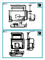
2
42 1/2” - 1081 mm
43 1/4” - 1098 mm
20 1/8” - 510 mm
28 1/8” - 715 mm
29” - 738 mm
40 3/8” - 1026 mm
max 15 3/4” - 400 mm
8 5/8” - 220 mm
3 5/8”
92 mm
3 2/8” - 84 mm
13 3/8” - 341 mm
10 7/8”
275 mm
4”
103 mm
4 1/4”
109 mm
3 1/2”
90 mm
42 1/2” - 1081mm
8 5/8” - 220 mm
3 1/2”
90 mm
12 1/8” - 308 mm
4 1/4”
109 mm
4”
103 mm
34 5/8” - 879 mm
101 lb
46 kg
Down draft 120
81 lb
37 kg
4 1/2”
109 mm
3 1/4” - 84 mm
13 3/8” - 341mm
3 5/8” - 92 mm
31 3/8” - 798 mm
28 5/8” - 726 mm
32 1/2” - 824 mm
29” - 738 mm
0,06”
1,5 mm
13 1/4”
336 mm
10 7/8”
275 mm
4 1/8”
104 mm
28 1/8” - 715 mm
max 15 3/4” - 400 mm
30 3/4” - 781 mm
30 3/4” - 781 mm
8 5/8”
220 mm
3 1/2”
90 mm
3 5/8”
92 mm
9 3/8” - 237 mm
15 3/8” - 390,5 mm
3 1/4”
82 mm
Down draft 90

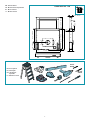
3
Down draft 90 - 120
9 1/2” - 241 mm 18 5/8” - 474 mm
max 15 3/4” - 400 mm
29” - 738 mm
28 1/8” - 715 mm
30 3/4” - 781 mm
3 1/4” - 84 mm
0,06”
1,5 mm
4 1/2”
109 mm
3 5/8” - 92 mm
EN - Remote motor.
FR - Moteur monté séparément.
ES - Motor externo.
IT - Motore remoto.
ø5/16"
8 mm
ø1/4"
6 mm
EN- tool required
FR- outil requis
ES- herramienta
requerida
IT - Attrezzi necessari

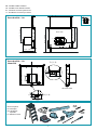
4
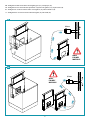
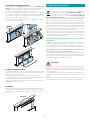
EN - Installation with back motor
FR - Installation avec moteur à l'arrière
ES - Instalación con motor parte trasera
IT - Installazione con motore posteriore
15 5/8” - 396 mm
20 1/8” - 510 mm
20 1/8” - 510 mm
29” - 737 mm
34 5/8” - 879 mm
Rear view
side front hood
2 3/4”
24 mm
1”
B (1 : 4)
1/8”
2,4 mm
2 1/4”
57 mm
1 1/4”
32,6 mm
D (1 : 3)
Motor PIN
Down draft 90 - 120
Down draft 90 - 120
ø5/16"
8 mm
ø1/4"
6 mm
EN- tool required
FR- outil requis
ES- herramienta
requerida
IT - Attrezzi necessari

5
EN - Recess hole dimensions (1),
xing to the supporting surface (2)
FR -
Dimensions du trou pour l'encastrement (1),
xation sur le plan d'appui (2)
ES - Medidas oricio para encajar (1),
jación en el plano de apoyo (2)
IT - Misure foro per incasso (1),
ssaggio al piano d'appoggio (2)
31 7/8” - 810 mm
43 6/8” - 1110 mm
3 7/8” - 98 mm
2 3/8” - 60 mm
28 1/8” - 715 mm
motor pin
29” - 738 mm max
1
2
2 3/4”
70 mm
2 1/4”
57 mm
2
1
EN - Ideal size.
FR - Mesure idéale.
ES - Medida ideal.
IT - Misura ideale.

6
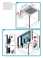
EN - Temporary electrical connection (3);
opening the hood for installation (4)(5).
FR - Branchement électrique provisoire (3);
ouverture de la hotte pour l'installation (4) (5).
ES - Conexión eléctrica provisional (3);
apertura de la campana para la instalación (4)(5).
IT - Collegamento elettrico provvisorio (3);
apertura della cappa per installazione (4)(5).
230V
3 seconds
230V
3
4 5

7
INLET
5
6
OUTLET
6
7
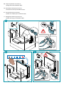
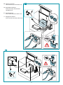
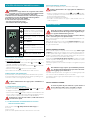
EN - Replace the original “inlet” (5) with the bracket xing the motor
to the hood (6); secure the motor to the hood if the air exhaust
is on the front (7). For other directions see (8) (9).
FR - Remplacer "inlet" original (5), avec l'étrier de xation du moteur
sur la hotte (6) ; xer le moteur à la hotte si la sortie d'air est
frontale (7). Voir (8) (9) pour d'autres directions.
ES - Reemplazar "inlet" original (5), con abrazadera de jación mo-
tor en la campana (6); jar el motor en la campana si la salida
del aire es frontal (7). Véase (8) (9) para otras direcciones.
IT - Sostituire "inlet" originale (5), con staa di ssaggio motore sul-
la cappa (6); ssare il motore alla cappa se l'uscita aria è frontale
(7). Vedere (8) - (9) per altre direzioni.

8
360°
AIR
9
x 8
4
2
1
180°
3
90°
5
x 8
6
OUTLET
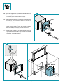
EN - Side movement of the air exhaust
FR - Déplacement latéral de la sortie d'air
ES -
Desplazamiento lateral de la salida del aire
IT - Spostamento laterale dell'uscita aria
8

9
360°
AIR
6
OUTLET
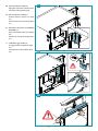
EN - Conguration with back motor
FR - Conguration avec moteur à l'arrière
ES - Conguración con motor parte trasera
IT - Congurazione con motore posteriore
1
11 12
10

10
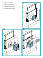
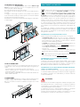
EN - Conguration with remote motor: Rectangular pipes (13); round pipes (14).
FR - Conguration avec moteur monté séparément : Tuyaux rectangulaires (13) ; tuyaux ronds (14).
ES - Conguración con motor externo: Tubos rectangulares (13); tubos redondos (14).
IT - Congurazione con motore remoto: Tubi rettangolari (13); tubi tondi (14).
3 1/2”
90mm
8 5/8” - 220 mm
Motor
Motor
13
14
ONLY
FALMEC
MOTORS!
ONLY
FALMEC
MOTORS!

11
15
EN - Electrical connection:
onboard motor (15); remote motor (16).
FR - Branchement électrique :
moteur à bord (15) ; moteur monté
séparément (16);
ES - Conexión eléctrica:
motor a bordo (15); motor externo (16).
IT - Collegamento elettrico:
motore a bordo (15); motore remoto (16).
16

12
Magnets
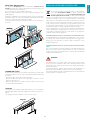
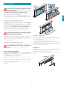
EN - Brackets xing to the TOP (17).
Fixing the control unit to the hood (18).
Hand anti-crushing warning (19).
FR - Étriers de xation au TOP (17).
Fixation unité de contrôle à la hotte
(18).
Avertissement anti-écrasement des mains
(19).
ES - Abrazaderas de jación a la SUPERFICIE
DE APOYO (17).
Fijación unidad de control a la campana
(18).
Advertencia contra aplastamiento manos
(19).
IT - Stae di ssaggio al TOP (17).
Fissaggio unita di controllo alla cappa
(18).
Avvertenza anti schiacciamento mani
(19).
19
18
17

13
ENGLISH
SAFETY INSTRUCTIONS
AND WARNINGS
Installation operations are to be carried
out by skilled and qualied installers in ac-
cordance with the instructions in this book-
let and in compliance with the regulations in
force.
DO NOT use the hood if the power supply cable
or other components are damaged: disconnect
the hood from the electrical power supply and con-
tact the Dealer or an authorised Servicing Dealer for
repairs.
Do not modify the electrical, mechanical or func-
tional structure of the equipment.
Do not personally try to carry out repairs or re-
placements. Interventions carried out by incom-
petent and unauthorised persons can cause seri-
ous damage to the unit or physical and personal
harm, not covered by the Manufacturer's warran-
ty.
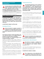
WARNINGS FOR THE INSTALLER
TECHNICAL SAFETY
Before installing the hood, check the in-
tegrity and function of each part. Should
anomalies be noted, do not proceed with
installation and contact the Dealer.
Do NOT install the hood if an aesthetic (or cos-
metic) defect has been detected. Put it back into
its original package and contact the dealer.
No claim can be made for aesthetic (or cosmetic)
defects once it has been installed.
During installation, always use personal protective
equipment (e.g.: Safety shoes) and adopt prudent
and proper conduct.
The installation kit (screws and plugs) supplied with
the hood is only to be used on masonry walls: in case
of installation on walls of a dierent material, assess
other installation options keeping in mind the type of
wall surface and the weight of the hood (indicated on
spec sheets at the beginning of this manual).
Keep in mind that installations with dierent types of
fastening systems from those supplied, or which are
not compliant, can cause electrical and mechanical
seal danger.
Do not install the hood outdoors and do not expose
it to atmospheric elements (rain, wind, etc.).
ELECTRICAL SAFETY
The electrical system to which the hood is
to be connected must be in accordance
with local standards and supplied with
earthed connection in compliance with safety
regulations in the country of use. It must also
comply with local standards regarding radio anti-
static properties.
Before installing the hood, check that the electrical
mains power supply corresponds with what is report-
ed on the identication plate located inside the hood.
The socket used to connect the installed equipment
to the electrical power supply must be within reach:
otherwise, install a mains switch to disconnect the
hood when required.
Any changes to the electrical system must be carried
out by a qualied electrician.
The maximum length of the ue fastening screws
(supplied by the manufacturer) must be 13 mm. Use
of non-compliant screws with these instructions can
lead to danger of an electrical nature.
Do not try to solve the problem yourself in the event
of equipment malfunction, but contact the Dealer or
an authorised Servicing Department for repairs.
When installing the hood, disconnect
the equipment by removing the plug or
switching o the main switch.
FUMES DISCHARGE SAFETY
Do no connect the equipment to discharge
pipes of fumes produced from combustion
(for example boilers, replaces, etc.).
Before installing the hood, ensure that all standards in
force regarding discharge of air out of the room have
been complied with.
USER WARNINGS
These warnings have been drawn up for
your personal safety and those of others.
You are therefore kindly asked to read the
booklet carefully in its entirety before using the
or cleaning the equipment.
The Manufacturer declines all responsibility for
any damage caused directly, or indirectly, to per-
sons, things and pets as a consequence of failing
to comply with the safety warnings indicated in
this booklet.

14
It is imperative that this instructions booklet is
kept together with the equipment for any future
consultation.
If the equipment is sold or transferred to another per-
son, make sure that the booklet is also supplied so
that the new user can be made aware of the hood's
operation and relative warnings.
After the stainless steel hood has been installed, it
will need to be cleaned to remove any residues re-
maining from the protective coating as well as any
grease and oil stains which, if not removed, can cause
irreversible damage to the hood surface. To properly
clean the unit, the manufacturer recommends using
the supplied moist wipes, which are also available
sold separately.
Insist on original spare parts.
INTENDED USE
The equipment is solely intended to be used to
extract fumes generated from cooking food in
non-professional domestic kitchens: any other
use is improper. Improper use can cause damage
to persons, things, pets and exempts the Manu-
facturer from any liability.
The equipment can be used by children over the age
of 8 and by persons with reduced physical, sensory
and mental abilities, or with no experience or knowl-
edge, as long as they do so under supervision or after
having received relative instructions regarding safe
use of the equipment and understanding of the dan-
gers connected to it.
Children are not to play with the equipment. Clean-
ing and maintenance by the user must not be carried
out by children without supervision.
USE AND CLEANING WARNINGS
Before cleaning or carrying out mainte-
nance operations, disconnect the equip-
ment by removing the plug or switching
o the main switch.
Do not use the hood with wet hands or bare feet.
Always check that all electrical parts (lights, extractor
fan) are o when the equipment is not being used.
The maximum overall weight of any objects placed
or hung (if applicable) on the hood must not exceed
3lb 5oz (1.5 Kg).
Always supervise the cooking process during the use
of deep-fryers: Overheated oil can catch re.
Do not leave open, unattended ames under the
hood.
Do not prepare food over an open ame under the
hood.
Never use the hood without the metal anti-grease
lters: in this case, grease and dirt will deposit in the
equipment and compromise its operation.
Accessible parts of the hood can be hot when used at
the same time as the cooking appliances.
Do not carry out any cleaning operations when parts
of the hood are still hot.
There can be a risk of re if cleaning is not carried out
according to the instructions and products indicated
in this booklet.
Disconnect the main switch when the equipment is
not used for long periods of time.
If other appliances that use gas or other fu-
els are being used at the same time (boiler,
stove, replaces, etc.), make sure the room
where the fumes are discharged is well-ventilat-
ed, in compliance with the local regulations.
INSTALLATION
Intended only for qualied personnel
Before installing the hood, carefully read the section 'SA-
FETY INSTRUCTIONS AND WARNINGS'.
TECHNICAL FEATURES
The technical specications are exhibited on the labels located inside
the hood.
POSITIONING
The minimum distance between the highest part of the cooking
equipment and the lowest part of the hood is indicated in the in-
stallation instructions.
Should the instructions for the gas cooker specify a greater distance,
this must be taken into consideration.
Do not install the hood outdoors and do not expose it to outdoor envi-
ronment (rain, wind, etc.).
ELECTRICAL CONNECTION
(Intended only for qualied personnel)
Disconnect the equipment from electrical mains power
supply before carrying out any operations on the hood.
Ensure that the wires inside the hood are not disconnected
or cut:
in the event of damage, contact your nearest Servicing Depart-
ment.
Refer to qualied personnel for electrical connections.
Connection must be carried out in compliance with the provisions
of law in force.
Before connecting the hood to the electrical mains power supply,
check that:
• voltage supply corresponds with what is reported on the data plate
located inside the hood;
• the electrical system is compliant and can withstand the load (see
the technical specications located inside the hood);
• the power supply plug and cable do not come into contact with
temperatures exceeding 158°F (70 °C);
• the power supply system is eectively and properly connected to
earth in compliance with regulations in force;
•
the socket used to connect the hood is within reach.

15
ENGLISH
In case of:
• devices tted with cables without a plug: the type of plug to use is
a ''standardised'' one. The wires must be connected as follows: yel-
low-green for grounding, blue for neutral and brown for the live. The
plug must be connected to an adequate safety socket.
•
xed equipment not provided with a power supply cable and plug,
or any other device that ensures disconnection from the electrical
mains, with an opening gap of the contacts that enables total discon-
nection in overvoltage category III conditions.
Said disconnection devices must be provided in the mains power
supply in compliance with installation regulations.
The cable must not be cut o by the switch.
The Manufacturer declines all responsibility for failure to comply with
the safety regulations.
FUMES DISCHARGE
EXTERNAL EXHAUST HOOD SUCTION
In this version the fumes and vapours are discharged
outside through the exhaust pipe.
To this end, the hood outlet tting must be connected
via a pipe, to an external output.
The outlet pipe must have:
• a diameter not less than that of the hood tting.
• a slight slope downwards (drop) in the horizontal sections to prevent
condensation from owing back into the motor.
• the minimum required number of bends.
• the minimum required length to avoid vibrations and reduce the
suction performance of the hood.
You are required to insulate the pipes if it passes through cold envi-
ronments.
In the presence of motors with 800m
3
/h or higher, a check valve is
present to prevent external air owing back.
ASSEMBLY INSTRUCTIONS
Intended only for qualied personnel
The hood can be installed in various congurations.
The generic assembly steps apply to all installations; for
each case, follow the specic steps provided for the re-
quired installation.
OPERATION
WHEN TO TURN ON THE HOOD?
Switch on the hood at least one minute before starting to cook to direct
fumes and vapours towards the suction surface.
After cooking, leave the hood operating until complete extraction of all
vapours and odours. By means of the Timer function, it is possible to set
auto switch-o function which will allow the hood to turn o automat-
ically after 15 minutes of operation.
WHICH SPEED IS TO BE SELECTED?
1st speed: maintains the circulation of clean air with low electricity
consumption.
2nd speed: normal conditions of use.
3rd speed: presence of strong odours and vapours.
4th speed: rapid disposal of odours and vapours.
WHEN SHOULD THE FILTERS BE WASHED OR REPLACED?
The metal lters must be cleaned every 30 hours of operation.
The active carbon lters must be replaced every 3-4 months, depend-
ing on the use of the hood.
For further details refer to the “MAINTENANCE” section.
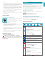
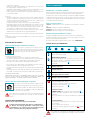
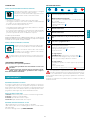
TOUCH PUSHBUTTON PANEL
ON/OFF (Blue led steady on)
Motor on/o and Speed 1
ON/OFF (blue led ashing)
If pressed for more than 3 seconds, it activates the 24h cycle
(1h ON -> 3h
OFF -> 1h ON)
the function deactivates if:
- The motor turns o (key )
- After 24h
Speed 2 activation
Speed 3 activation
Speed 4 activation for a few minutes only
Light on/o
TIMER (Red LED ashing)
Auto switch-o after 15 min.
The function deactivates (red LED o) if:
- The motor turns o (key ).
- The speed is changed.
With hood open:
FILTER ALARM (red LED steady on)
Anti-grease lter maintenance after approximately 30 hours
of operation.
Press the meter for 3 seconds to reset.
With hood closed:
If pressed for over 3 seconds, the hood opens for maintenan-
ce.
No control active.
To close the hood, press ( ) again for 3 seconds.

16
If the pushbutton panel is completely inactive, before con-
tacting the Technical assistance service, disconnect power
temporarily to the appliance (about 5“), possibly by acting on
the main switch, to restore normal operation.
If this measure has no eect, contact the Technical assistance service.
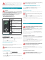
USING THE RADIO CONTROL (OPTIONAL)
WARNINGS!:
Place the hood away from sources of electromagnetic
waves (e.g. microwave ovens), which could interfere with
the radio control and with the hood electronics.
The maximum operating distance is 5 metres, that may vary ac-
cording to the presence of electromagnetic interferences.
Radio control operated at 433.92MHz.
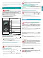
The radio control consists of two parts:
- the receiver built into the hood;
- the transmitter shown here in the gure.
DESCRIPTION OF TRANSMITTING
COMMANDS
UP
Motor switch-on and speed in-
crease from 1 to 4. Speed 4 is only
active for a few minutes.
DOWN
Speed decrease and motor
switch-o.
Light ON-OFF
TIMER ON: The motor automati-
cally switches o after 15 min.
The function is automatically dis-
abled if the motor is switched o
( key)
Command transmission active
ACTIVATION PROCEDURE
Before using the radio control, follow the procedure below on the
hood pushbutton panel:
• Press LIGHT (
) and TIMER ( ) simultaneously until all LEDs start
ashing.
• Release the two keys and press LIGHT (
) again until all LEDs are lit
up.
• Release LIGHT (
): now the receiver is active.
This procedure is also used to deactivate the receiver.
RADIO CONTROL CODE CHANGE
With only one radio control, go directly to point 2.
With several radio controls in the same room, a new code can be creat-
ed by following the procedure below.
Disconnect the power to the hood before starting the pro-
cedure.
1 CREATE A NEW CODE
The procedure is to be carried out on the radio control.
• Press LIGHT and TIMER simultaneously until the display starts
ashing.
• Press DOWN
on the radio control: saving is conrmed by three
brief ashes of the display. The new code cancels and replaces the
previous default code.
Reconnect the hood to the electrical power supply, making
sure that the lights and motor are o.
2 ASSOCIATING THE RADIO CONTROL WITH THE HOOD
USING THE TOUCH PUSHBUTTON PANEL
press LIGHT (
) on the hood pushbutton panel for 2 seconds:
the LED lights up.
press any key on the radio control within 10 seconds.
RESTORING DEFAULT CODE
the procedure is to be carried out if the hood is disposed of, sold or
transferred.
Disconnect the power to the hood before starting the pro-
cedure.
• Press UP
and DOWN simultaneously on the radio control for
more than 5 seconds: reset is conrmed by three brief ashes of the
display.
• Reconnect the hood to the electrical power supply.
• Proceed with associating the hood and the radio control, as described
in
point 2.
MAINTENANCE
Before cleaning or carrying out maintenance operations,
disconnect the equipment by removing the plug or
switching o the main switch.
Do not use detergents containing abrasive, acidic or corrosive
substances or abrasive cloths.
Regular maintenance guarantees proper operation and performance
over time.
Special attention is to be paid to the metal anti-grease lters: fre-
quent cleaning of the lters and their supports ensures that no am-
mable grease is accumulated.
CLEANING OF EXTERNAL SURFACES
You are advised to clean the external surfaces of the hood at least once
every 15 days
to prevent oily substances and grease from sticking to
them. To clean the brushed stainless steel hood, the Manufacturer rec-
ommends using "Magic Steel" wipes.
Alternatively and for all the other types of surfaces, it can be cleaned
using a damp cloth, slightly moistened with mild, liquid detergent or
denatured alcohol.
Complete cleaning by rinsing well and drying with soft cloths.
Do not use too much moisture or water around the push
button control panel and lighting devices in order to pre-
vent humidity from reaching electronic parts.
The glass panels can only be cleaned with specic, non-corrosive or
non-abrasive detergents using a soft cloth.
The Manufacturer declines all responsibility for failure to comply with
these instructions.
CLEANING OF INTERNAL SURFACES
Do not clean electrical parts, or parts related to the motor
inside the hood, with liquids or solvents.
For the internal metal parts, see the previous paragraph.

17
ENGLISH
METAL ANTI-GREASE FILTERS
It is advised to frequently wash the metal lters (at least once a
month) leaving them to soak in boiling water and cleaning solution for
1 hour, taking care not to bend them.
Do not use corrosive, acid or alkaline detergents.
Rinse them well and wait for them to be completely dry before reas-
sembling them.
Washing in a dishwasher is permitted, however, it may cause the lter
material to darken: to reduce the possibility of this problem from hap-
pening, use low-temperature washes (55°C max.).
To extract and insert the metal anti-grease lters see the assembly in-
structions.
1
4
3
MAGNET
2
CARBON-ZEO FILTERS
Under normal conditions, they should be regenerated every 18 months
and replaced after 3 years. To regenerate the lter, follow the following
procedure:
- Remove the lter as described in the instructions.
- Place the 4 lters (3 x type A and 1 x type B) in a domestic oven at
200°C for about 2 hours.
- When the lter has cooled down, ret the 4 lters onto the metal
structure of the KACL.930 lter.
LIGHTING
The range hood is equipped with high eciency, low consumption
LED spotlights with an extremely long life-span under normal use con-
ditions.
Should replacement be required, contact a service centre.
Magnets
DISPOSAL AFTER END OF USEFUL LIFE
The crossed-out trash or refuse bin symbol on the appliance
means that the product is WEEE, i.e. “Waste electrical and
electronic equipment'', accordingly it must not be disposed
of with regular unsorted waste (i.e. with ''mixed household
waste''), but it must be disposed of separately so that it can undergo
specic processing for its re-use, or a specic treatment, to remove and
safely dispose of any substances that may be harmful to the environ-
ment and remove the raw materials that can be recycled. Proper dis-
posal of these products contributes to saving valuable resources and
avoid potential negative eects on personal health and the environ-
ment, which may be caused by inappropriate disposal of waste.
You are kindly asked to contact your local authorities for further infor-
mation regarding the designated waste collection points nearest to
you. Penalties for improper disposal of such waste can be applied in
compliance with national regulations.
INFORMATION ON DISPOSAL IN EUROPEAN UNION COUNTRIES
The EU WEEE Directive was implemented dierently in each country,
accordingly, if you wish to dispose of this appliance we suggest con-
tacting your local authorities or dealer to nd out what the correct
method of disposal is.
INFORMATION ON DISPOSAL IN NONEUROPEAN UNION COUN
TRIES
The crossed-out trash or refuse bin symbol is only valid in the European
Union: if you wish to dispose of this appliance in other countries, we
suggest contacting your local authorities or dealer to nd out what the
correct method of disposal is.
WARNING!
The Manufacturer reserves the right to make changes to the equip-
ment at any time and without prior notice. Printing, translation and
reproduction, even partial, of this manual are bound by the Manufac-
turer's authorisation.
Technical information, graphic representations and specications in
this manual are for information purposes and cannot be divulged.
This manual is written in Italian. The Manufacturer is not responsible for
any transcription or translation errors.

18
CONSIGNES DE SÉCURITÉ
ET MISES EN GARDE
Le travail d'installation doit être eectué
par des installateurs compétents et quali-
és, conformément aux indications du pré-
sent manuel et en respectant les normes en vi-
gueur.
Si le câble d'alimentation ou d’autres composants
sont endommagés, la hotte NE doit PAS être utili-
sée: débrancher la hotte de l'alimentation électrique
et contacter le revendeur ou un Centre d’Assistance
technique agréé pour la réparation.
Ne pas modier la structure électrique, méca-
nique et fonctionnelle de l'appareil.
Ne pas tenter d'eectuer soi-même des répara-
tions ou des remplacements : les interventions
eectuées par des personnes non compétentes
et non qualiées peuvent provoquer des dom-
mages, éventuellement très graves, à des choses
et/ou à des personnes, non couverts par la garan-
tie du Fabricant.
MISES EN GARDE POUR L’INSTALLATEUR
SÉCURITÉ TECHNIQUE
Avant d'installer la hotte, contrôler l'inté-
grité et la fonctionnalité de chaque partie:
en cas de constatation d'anomalies, ne pas
procéder à l'installation et contacter le Reven-
deur.
En cas de constatation d'un défaut esthétique, la
hotte NE doit PAS être installée; la remettre dans
son emballage d’origine et contacter le Reven-
deur.
Après son installation, aucune réclamation ne sera
acceptée pour des défauts esthétiques.
Pendant l'installation, toujours utiliser des équipe-
ments de protection individuelle (ex.: des chaussures
de sécurité) et adopter un comportement prudent et
correct.
Le kit de xation (vis et chevilles) fourni avec la hotte
est utilisable uniquement sur des murs en maçonne-
rie: s'il faut installer la hotte sur des murs de maté-
riau diérent, évaluer d’autres systèmes de xation en
tenant compte de la résistance du mur et du poids de
la hotte (indiqué à la page 2).
Tenir compte du fait que l'installation avec des sys-
tèmes de xation diérents de ceux fournis ou non
conformes peut comporter des risques de nature
électrique et de tenue mécanique.
Ne pas installer la hotte à l’extérieur et ne pas l’expo-
ser à des agents atmosphériques (pluie, vent, etc.).
SÉCURITÉ ÉLECTRIQUE
Le circuit électrique, auquel est reliée la
hotte, doit être aux normes et muni d’un
raccordement à la terre, conformément
aux normes de sécurité du pays d’utilisation ; il
doit en outre être conforme aux normes euro-
péennes sur l'antiparasite radio.
Avant d'installer la hotte, s'assurer que la tension du
secteur correspond à celle reportée sur la plaque qui
se trouve à l'intérieur de la hotte.
La prise utilisée pour le branchement électrique doit
être facilement accessible avec l'appareil installé: si
cela n'était pas possible, prévoir un interrupteur gé-
néral pour déconnecter la hotte en cas de besoin.
Toute modication de l'installation électrique devra
être uniquement eectuée par un électricien qualié.
La longueur maximum de la vis de xation de la
cheminée (fournie par le fabricant) est de 13 mm.
L'utilisation de vis non conformes avec les présentes
instructions peut comporter des risques de nature
électrique.
En cas de dysfonctionnements de l'appareil, ne pas
tenter de résoudre personnellement le problème,
mais contacter le revendeur ou un Centre d'Assis-
tance agréé pour la réparation.
Pendant l'installation de la hotte, débran-
cher l'appareil en retirant la prise ou en
agissant sur l'interrupteur général.
SÉCURITÉ ÉVACUATION DES FUMÉES
Ne pas raccorder l'appareil aux conduits
d'évacuation des fumées produites par la
combustion (par ex. chaudières, chemi-
nées, etc.)
Avant l'installation de la hotte, s'assurer que toutes
les normes en vigueur sur l’évacuation de l'air à l'exté-
rieur de la pièce sont respectées.
MISES EN GARDE POUR L'UTILISATEUR
Ces mises en garde ont été rédigées pour
votre sécurité et pour celle d'autrui, nous
vous prions donc de lire attentivement
toutes les parties de ce manuel avant d'utiliser
l'appareil ou de le nettoyer.
Le fabricant décline toute responsabilité pour
d’éventuels dommages, directs ou indirects, pou-
vant être causés aux personnes, aux choses et
aux animaux domestiques, suite au non-respect
des mises en garde de sécurité indiquées dans ce

19
FRANÇAIS
manuel.
Il est très important que ce manuel d'instructions
soit conservé avec l'appareil pour toute consulta-
tion future.
Si l'appareil devait être vendu ou transféré à une autre
personne, s'assurer que le manuel soit remis avec ce-
lui-ci, de manière à ce que le nouvel utilisateur puisse
connaître le fonctionnement de la hotte et des mises
en garde relatives.
Après l'installation des hottes en acier inox, il est né-
cessaire d'eectuer le nettoyage de celles-ci pour re-
tirer les résidus de colle de la protection et les taches
éventuelles de graisse et d'huile qui, si on ne les en-
lève pas, peuvent être cause de détérioration irréver-
sible de la surface de la hotte. Pour cette opération,
le fabricant conseille d'utiliser les serviettes fournies,
disponibles même à l'achat.
Exiger des pièces de rechange originales.
DESTINATION D'UTILISATION
L'appareil est destiné, seulement et exclusivement,
pour l'aspiration de fumées générées par la cuisson
d'aliments en milieu domestique, non profession
-
nel: toute autre utilisation diérente de celle-ci est
impropre et peut provoquer des dommages à des
personnes, choses et animaux domestiques, et dé
-
gage le Fabricant de toute responsabilité.
L'appareil peut être utilisé par des enfants de plus
de 8 ans et des personnes ayant des capacités phy-
siques, sensorielles ou mentales réduites, ou dépour-
vues d'expérience ou de connaissances nécessaires,
pourvu qu’ils soient sous surveillance ou bien après
qu’ils aient reçu les instructions relatives à une utilisa-
tion sûre de l'appareil et qu’ils aient compris les dan-
gers correspondants.
Les enfants ne doivent pas jouer avec l'appareil. Le
nettoyage et la maintenance destinés à être eectués
par l'utilisateur ne doivent pas être eectués par des
enfants sans surveillance.
MISES EN GARDE POUR L'UTILISATION ET LE
NETTOYAGE
Avant de procéder à toute opération de
nettoyage ou d'entretien, désactiver l'ap-
pareil en enlevant la che ou en agissant
sur l'interrupteur général.
Ne pas utiliser la hotte avec les mains mouillées ou les
pieds nus.
Contrôler toujours que toutes les parties électriques
(lumières, aspirateur) soient éteintes lorsque l'appa-
reil n'est pas utilisé.
Le poids maximum total d'éventuels objets position-
nées ou suspendus (où c'est prévu) sur la hotte ne
doit pas dépasser 1,5 kg.
Contrôler les friteuses pendant l'utilisation: l'huile sur-
chauée pourrait s'enammer.
Ne pas allumer de ammes nues sous la hotte.
Ne pas cuisiner avec une amme nue sous la hotte.
Ne jamais utiliser la hotte sans les ltres métalliques
anti-graisse ; dans ce cas, la graisse et la saleté se
déposeraient dans l'appareil et compromettrait son
fonctionnement.
Des parties accessibles de la hotte peuvent être
chaudes si elles sont utilisées avec des appareils de
cuisson.
Ne pas eectuer d’opérations de nettoyage si des
parties de la hotte sont encore chaudes.
Si le nettoyage n'est pas mené conformément aux
modalités et avec les produits indiqués dans le pré-
sent manuel, un risque d’incendie est possible.
Couper l'interrupteur général si l'appareil n'est pas
utilisé pendant de longues périodes.
En cas d'utilisation simultanée avec
d'autres éléments (chaudières, poêles, che-
minées, etc.) alimentés au gaz ou avec
d'autres combustibles, pourvoir à une ven-
tilation adéquate du local où s'eectue l'aspira-
tion de la fumée, conformément aux normes en
vigueur.
INSTALLATION
partie réservée uniquement à un personnel qualié
Avant d’eectuer l'installation de la hotte, lire attentive-
ment le chap. « CONSIGNES DE SÉCURITÉ ET MISES EN
GARDE».
Utiliser des tables de cuisson ayant une puissance thermi-
que maximale de 12 kW.
CARACTÉRISTIQUES TECHNIQUES
Les données techniques de l'appareil sont reportées sur des étiquettes
placées à l'intérieur de la hotte.
POSITIONNEMENT
La distance minimum entre la partie la plus haute de l'appareil de
cuisson et la partie la plus basse de la hotte de cuisine est indi-
quée dans les instructions de montage.
Si les instructions de la table de cuisson au gaz spécient une distance
supérieure, il faut en tenir compte.
Ne pas installer la hotte à l’extérieur et ne pas l’exposer à des agents
atmosphériques (pluie, vent, etc.).
BRANCHEMENT ÉLECTRIQUE
(partie réservée uniquement à un personnel qualié)
Avant d'eectuer toute opération sur la hotte, débrancher
l'appareil du réseau électrique.
Veiller à ce que les ls électriques à l'intérieur de la hotte ne
soient pas débranchés ou coupés:
dans le cas contraire, contacter le Centre d'Assistance le plus
proche.
Pour le raccordement électrique contacter un personnel qualié.
Le raccordement doit être eectué conformément aux disposi-
tions de lois en vigueur.
Avant de raccorder la hotte au réseau électrique, contrôler que:
• la tension du secteur corresponde à celle reportée sur la plaque des
données qui se trouve à l'intérieur de la hotte;
• le circuit électrique soit aux normes et puisse supporter la charge
de l'appareil (voir la plaque des caractéristiques techniques située à

20
l'intérieur de la hotte);
• la che et le câble d'alimentation ne rentrent pas en contact avec
des températures supérieures à 70 °C;
• l’installation d'alimentation soit munie d'un raccordement à la terre
ecace et correct, conformément aux normes en vigueur;
• la prise utilisée pour le branchement soit facilement accessible, une
fois la hotte installée.
En cas d':
• appareils équipés d'un câble sans che: la che à utiliser doit être
du type «normalisé». Les ls doivent être raccordés de la manière
suivante: le l jaune-vert doit pour la mise à la terre, le l bleu pour
le neutre et le l marron pour la phase.
La che doit être raccordée à une prise de sécurité adéquate.
• appareil xe dépourvu de câble d'alimentation et de che ou d'un
autre dispositif qui assure la déconnexion du réseau, avec une dis-
tance d'ouverture des contacts permettant la déconnexion com-
plète dans les conditions de la catégorie de surtension III.
Ces dispositifs de déconnexion doivent être prévus dans le réseau
d'alimentation conformément aux règles d'installation.
Le câble de terre jaune/vert ne doit pas être interrompu par l'interrup-
teur.
Le Fabricant décline toute responsabilité si les normes de sécurité ne
sont pas respectées.
ÉVACUATION DES FUMÉES
HOTTE À ÉVACUATION EXTÉRIEURE ASPIRANTE
Dans cette version, les fumées et les vapeurs sont en-
voyées vers l'extérieur à travers un tuyau d'évacuation.
À cette n, le raccord de sortie de la hotte doit être rac-
cordé par un tuyau à une sortie extérieure.
Le tuyau de sortie doit avoir:
• un diamètre égal ou supérieur à celui du raccord de la hotte.
• une légère inclinaison vers le bas (chute) dans les tronçons horizon-
taux pour éviter que la condensation ne reue dans le moteur.
• un nombre de coudes réduit au minimum (pas plus de 3).
• une longueur de conduit réduite au minimum pour éviter toute vi-
bration et réduire la capacité aspirante de la hotte.
Il est nécessaire d'isoler la tuyauterie si elle passe par des endroits non
chaués.
Pour empêcher les retours d'air de l'extérieur, un clapet de non retour
est installé en présence des moteurs avec 800 m3/h ou supérieurs.
Déviation pour l'Allemagne :
quand la hotte de la cuisine et des appareils alimentés avec une énergie dif-
férente de l'énergie électrique sont en fonction simultanément, la pression
négative dans la pièce ne doit pas dépasser 4 Pa (4 x 10⁻⁵ bars).
HOTTE À RECIRCULATION INTÉRIEURE FILTRANTE
Dans cette version, l'air passe à travers les ltres au char-
bon actif pour être purié et est recyclé dans la pièce.
Contrôler que les ltres au charbon actif soient montés
sur la hotte, sinon les appliquer comme indiqué dans
les instructions de montage.
Dans cette version, le clapet de non retour ne doit pas être mon-
té: le retirer s'il est présent sur le raccord de sortie de d'air du
moteur.
INSTRUCTIONS DE MONTAGE
partie réservée uniquement à un personnel qualié
La hotte peut être installée selon diverses congurations.
Les phases de montage génériques valent pour toutes
les installations; par contre, là où il est spécié, suivre les
phases correspondant à la conguration désirée.
FONCTIONNEMENT
QUAND FAUTIL ALLUMER LA HOTTE?
Allumer la hotte au moins une minute avant de commencer à cuisiner
pour canaliser les fumées et les vapeurs vers la surface d'aspiration.
Au terme de la cuisson, laisser la hotte en fonction jusqu'à l’aspiration
complète de toutes les vapeurs et odeurs: grâce à la fonction Timer, il
est possible de programmer l'arrêt automatique de la hotte au bout de
15 minutes de fonctionnement.
QUELLE VITESSE CHOISIR ?
I vitesse : maintient l'air pur avec de faibles consommations d'électri-
cité.
II vitesse: conditions normales d'utilisation.
III vitesse: présence de fortes odeurs et vapeurs.
IV vitesse: élimination rapide des odeurs et vapeurs.
QUAND LAVER OU CHANGER LES FILTRES ?
Les ltres métalliques doivent être lavés après 30 heures d'utilisation.
Les ltres au charbon actif (en option) doivent être remplacés tous les
3-4 mois selon l'utilisation de la hotte.
Pour toute information supplémentaire, voir le chap. « ENTRETIEN ».
TABLEAU TACTILE DES COMMANDES
ON/OFF (LED xe)
Marche/arrêt moteur et Vit1.
ON/OFF (LED clignotante)
Appuyer pendant plus de 3 secondes pour activer le cycle
24h (1h ON -> 3h OFF -> 1h ON) La fonction se désactive si:
- On éteint le moteur (touche
).
- Après 24h
Activation Vitesse 2
Activation Vitesse 3
Activation Vitesse 4 seulement pendant quelques mi-
nutes, puis la vitesse 3 s'active.
Allumage / extinction lumière
TIMER (LED rouge clignotante)
Arrêt automatique après 15 min.
La fonction se désactive (LED rouge éteinte) si:
- On éteint le moteur (touche
).
- On fait varier la vitesse.
Avec hotte ouverte :
ALARME FILTRES (LED rouge xe avec moteur OFF )
Entretien des ltres anti-graisse après environ 30 heures
d'utilisation.
Enfoncer pendant 3 secondes pour remettre le compteur à
zéro.
Avec hotte fermée :
S'il est appuyé pendant plus de 3 secondes, la hotte s'ouvre
pour l'entretien.
Aucune commande n'est activée.
Pour refermer la hotte, appuyer à nouveau sur( ) pendant
3 secondes.
Si le boîtier de commande est totalement inactif, avant de
contacter le service d’Assistance technique, couper momenta-
La pagina si sta caricando...
La pagina si sta caricando...
La pagina si sta caricando...
La pagina si sta caricando...
La pagina si sta caricando...
La pagina si sta caricando...
La pagina si sta caricando...
La pagina si sta caricando...
La pagina si sta caricando...
La pagina si sta caricando...
La pagina si sta caricando...
La pagina si sta caricando...
La pagina si sta caricando...
La pagina si sta caricando...
La pagina si sta caricando...
La pagina si sta caricando...
-
 1
1
-
 2
2
-
 3
3
-
 4
4
-
 5
5
-
 6
6
-
 7
7
-
 8
8
-
 9
9
-
 10
10
-
 11
11
-
 12
12
-
 13
13
-
 14
14
-
 15
15
-
 16
16
-
 17
17
-
 18
18
-
 19
19
-
 20
20
-
 21
21
-
 22
22
-
 23
23
-
 24
24
-
 25
25
-
 26
26
-
 27
27
-
 28
28
-
 29
29
-
 30
30
-
 31
31
-
 32
32
-
 33
33
-
 34
34
-
 35
35
-
 36
36


Falmec DOWN DRAFT 120 Manuale del proprietario
- Tipo
- Manuale del proprietario
- Questo manuale è adatto anche per
in altre lingue
Documenti correlati
-
Falmec Gruppo Incasso No-Drop Manuale utente
-
-
-
-
-
-
-
Falmec FDMOV36W5SB Guida utente
-
-