
29
36
71
10 1484
71
+1
0
29
+1
0
Danfoss
80G8086.01
MC
X MCX06DMMILDS MMILDSACCMMR
ACCCNX080G0083
CANbus CANbus
ACCCBI080G0239ACCCBI080G0239
POWER
SUPPLY
24 V AC
POWER SUPPLY
24 V AC
230 V AC
CAN
RJ1
CAN
RJ
CAN
RJ2
CANbus
MCX
LINK
POWER
SUPPLY
24 V AC
230 V AC
YELLOW
GREEN
RED
BLACK
Danfoss
80G8087.01
MYK connection
ww w.danfoss.com/mcx
DKRCC.PI.RJ0.H3.1U
3106000480
Via San Giuseppe 38/G
31015 Conegliano (TV) Italy
Tel: +39 0438 336611
Fax: +39 0438 336699
info.mcx@danfoss.com
www.danfoss.com
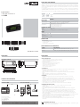
DIMENSIONI
Montaggio a pannello
Dima di foratura
SCHEMA DI COLLEGAMENTO
Connessione MCX Connessione MCX06D
CARATTERISTICHE GENERALI
MMILDS è un dispositivo di interfaccia remota della famiglia MCX. E’ dotato di un display a LED per la visualizzazione
di dati provenienti da un MCX o dalle 2 sonde che è possibile collegare localmente. La connessione con un qualsiasi
strumento della gamma MCX avviene attraverso la rete CAN bus. L’alimentazione può provenire dallo strumento
a cui è collegato.
Le informazioni sull’interfaccia utente risiedono a bordo del MCX e non è quindi necessaria alcuna programmazione
del MMILDS. MMILDS si alimenta tramite lo strumento a cui è direttamente collegato e automaticamente ne mostra
l’interfaccia utente; può però anche visualizzare l’interfaccia di un qualsiasi altro strumento connesso alla stessa rete.
MMILDS
DATI TECNICI
Ingressi analogici
- AI1: 0/20 mA, 4/20 mA, 0/5 V, 0/1 V, configurabili da software
- AI2: NTC, default 10 KΩ a 25 °C, configurabili da software
Alimentazione
- da MCX attraverso connettore telefonico RJ12
- 12 V DC ± 20% alimentatore esterno
- 12 V AC ± 15% alimentatore esterno
- massima potenza assorbita: 1,5 W
INTERFACCIA UTENTE
Display - LED 3-½ digit
Tastiera - 3 tasti
Montaggio - montaggio a pannello (vedi dima di foratura in figura)
VARIE
CANbus •
Seriale Modbus RS485
Buzzer
Orologio RTC
Grado di protezione - IP65
CODICE IDENTIFICATIVO PRODOTTO
CODICE DESCRIZIONE
080G0232 MMILDS, 12V, LED, CAN, REMOTE DISPLAY, PANEL, Single Pack
080G0233 MMILDS, 12V, LED, CAN, REMOTE DISPLAY, PANEL, Industrial Pack (25 pieces)
CONNESSIONI
- Connettore CAN
5 vie tipo JST PH passo 2 mm
- Connettore sonde
morsetto a vite 5 vie passo 3,5 mm
DKRCC.PI.RJ0.H3.1U / 520H5991 - MMILDS foglio istruzioni - P.N. 3106000480 - 15-310600048-D
SMALTIMENTO DEL PRODOTTO
- L’apparecchiatura (o il prodotto) deve essere oggetto di raccolta separata in conformità alle vigenti
normative locali in materia di smaltimento.
AVVERTENZE
ALTRE CARATTERISTICHE
- Condizioni di funzionamento CE: -20T60, 90% UR non condensante
- Condizioni di immagazzinamento: -30T80, 90% UR non condensante
- Da integrare in apparecchiature di classe I e/o II
- Grado di protezione: IP65
- Periodo di sollecitazione elettriche delle parti isolanti: lungo
- Adatto per l’uso in ambiente di polluzione normale
- Categoria di resistenza al calore e al fuoco: A
- Immunità contro le sovratensioni: categoria I
- Classe e struttura del software: A
CONFORMITÀ CE
Questo prodotto è progettato in modo da garantire la conformità con le seguenti direttive dell’Unione Europea:
- Direttiva bassa tensione: 73/23/EEC
- Compatibilità elettromagnetica EMC: 89/336/EEC e con le seguenti norme armonizzate:
- EN61000-6-1, EN61000-6-3 (immunità ed emissione per gli ambienti residenziali, commerciali e dell’industria
leggera)
- EN61000-6-2, EN61000-6-4 (immunità ed emissione per gli ambienti industriali)
- EN60730 (dispositivi elettrici automatici di comando per uso domestico e similare)
AVVERTENZE
- Ogni utilizzo diverso da quanto descritto nel presente manuale è da ritenersi improprio e non è pertanto
autorizzato
- Verificare che le condizioni limite di funzionamento a cui l’apparecchiatura è sottoposta rientrino tra quelle
specificate, in particolare per quanto riguarda la tensione di alimentazione e le condizioni ambientali
- Questa apparecchiatura contiene componenti elettrici sotto tensione e pertanto tutte le operazioni di servizio e
manutenzione su di essa possono essere eseguite solo da personale qualificato
- L’apparecchiatura non può essere utilizzata come dispositivo di sicurezza
- La responsabilità di lesioni o danni causati da uso improprio ricadrà esclusivamente sull’utilizzatore
AVVERTENZE PER L’INSTALLAZIONE
- L’installazione deve essere eseguita secondo le normative e legislazioni vigenti nel paese di utilizzo
dell’apparecchiatura
- Operare sui collegamenti elettrici sempre ad apparecchiatura non alimentata
- Prima di effettuare qualsiasi operazione di manutenzione sulla apparecchiatura, disinserire tutti i collegamenti
elettrici
- Non esporre l’apparecchiatura sotto continui getti d’acqua o ad un umidità maggiore del 90%. In generale evitare
l’esposizione ad atmosfere aggressive ed inquinanti, agli agenti atmosferici, ad ambienti ove sono presenti
esplosivi o miscele di gas infiammabili, alla polvere, a forti vibrazioni, a repentine variazioni di temperatura che
abbinate ad alta umidità possono provocare la formazione di condensa e a fonti di interferenze elettromagnetiche
(ad es. antenne trasmittenti)
- Usare cavo appropriato per le linee di comunicazione. Fare riferimento alla Guida di Installazione “MCX hardware network
specification” per il tipo di cavo da usare e le raccomandazioni da osservare nei collegamenti
- Ridurre il più possibile il percorso dei cavi dei sensori e degli ingressi digitali, allontanandoli dai cavi dei carichi
induttivi e di potenza per evitare possibili disturbi elettromagnetici
- Non avvicinare le dita ai componenti elettronici dell’apparecchiatura per evitare la generazione di scariche
elettrostatiche
Foglio istruzioni
Controllo elettronico
MMILDS
La Danfoss non si assume alcuna responsabilità circa eventuali errori nei cataloghi, pubblicazioni o altri documenti scritti. La Danfoss si riserva il diritto di modificare i suoi prodotti senza previo avviso, anche per i prodotti
già in ordine sempre che tali modifiche si possano fare senza la necessità di cambiamenti nelle specifiche che sono già state concordate.
Tutti i marchi di fabbrica citati sono di proprietà delle rispettive società. Il nome Danfoss e il logo Danfoss sono marchi depositati della Danfoss A/S. Tutti i diritti riservati.
© Danfoss A/S (RAC-DCS-IMCGP / az), 2016.07

29
36
71
10 1484
71
+1
0
29
+1
0
Danfoss
80G8086.01
MC
X MCX06DMMILDS MMILDSACCMMR
ACCCNX080G0083
CANbus CANbus
ACCCBI080G0239ACCCBI080G0239
POWER
SUPPLY
24 V AC
POWER SUPPLY
24 V AC
230 V AC
CAN
RJ1
CAN
RJ
CAN
RJ2
CANbus
MCX
LINK
POWER
SUPPLY
24 V AC
230 V AC
YELLOW
GREEN
RED
BLACK
Danfoss
80G8087.01
MYK connection
ww w.danfoss.com/mcx
DKRCC.PI.RJ0.H3.1U
3106000480
Via San Giuseppe 38/G
31015 Conegliano (TV) Italy
Tel: +39 0438 336611
Fax: +39 0438 336699
info.mcx@danfoss.com
www.danfoss.com
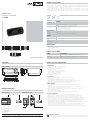
CONNECTION DIAGRAM
MCX connection MCX06D connection
PRODUCT PART NUMBER
CODE DESCRIPTION
080G0232 MMILDS, 12V, LED, CAN, REMOTE DISPLAY, PANEL, Single Pack
080G0233 MMILDS, 12V, LED, CAN, REMOTE DISPLAY, PANEL, Industrial Pack (25 pieces)
DKRCC.PI.RJ0.H3.1U / 520H5991 - MMILDS instruction sheet - P.N. 3106000480 - 15-310600048-D
DISPOSAL INSTRUCTION
- Equipment containing electrical components may not be disposed together with domestic waste. It
must be separately collected with electrical and electronic waste according to local and valid legislation.
GENERAL SPECIFICATIONS
MMILDS is MCX’s family remote interface. It’s fitted with a LED display for displaying data from a MCX or from 2
probes that can be locally connected. The connection with any MCX controller is through the CAN bus network.
The power supply can come from controller which it is connected.
All the information about the user interface is loaded inside the MCX controller; that’s why there is no need of
programming the MMILDS interface. MMILDS is powered from the controller which it is connected to and
automatically shows its user interface; but it can also show the interface of any other device connect to the same
network.
MMILDS
TECHNICAL SPEC.
Analog input
- AI1: 0/20 mA, 4/20 mA, 0/5 V, 0/1 V, selectable via software
- AI2: NTC, default 10 KΩ at 25 °C, selectable via software
Power supply
- from the MCX through the RJ12 telephone connector
- 12 V DC ± 20% external power supply
- 12 V AC ± 15% external transformers
- maximum power consumption: 1.5 W
USER INTERFACE
Display - LED 3-½ digit
Keyboard - 3 key
Mounting - panel mounting (see the drilling template in figure)
OTHERS
CANbus •
Modbus RS485 serial
interface
Buzzer
RTC clock
Degree of protection - IP65
CONNECTIONS
- CAN connector
5 way JST PH type pitch 2 mm
- Probe connector
5 way screw plug-in connector pitch 3.5 mm
DIMENSIONS
Panel mounting
Drilling template
GENERAL FEATURES AND WARNINGS
OTHER FEATURES
- Operating conditions CE: -20T60, 90% RH non-condensing
- Storage conditions: -30T80, 90% RH non-condensing
- To be integrated in Class I and/or II appliances
- Index of protection: IP65
- Period of electric stress across insulating parts: long
- Suitable for using in a normal pollution environment
- Category of resistance to heat and fire: A
- Immunity against voltage surges: category I
- Software class and structure: class A
CE COMPLIANCE
This product is designed to comply with the following EU standards:
- Low voltage guideline: 73/23/EEC
- Electromagnetic compatibility EMC: 89/336/EEC and with the following norms:
- EN61000-6-1, EN61000-6-3 (immunity for residential, commercial and light-industrial environments)
- EN61000-6-2, EN61000-6-4 (immunity and emission standard for industrial environments)
- EN60730 (Automatic electrical controls for household and similar use)
GENERAL WARNINGS
- Every use that is not described in this manual is considered incorrect and is not authorised by the
manufacturer
- Verify that the installation and operating conditions of the device respect the ones specified in the manual,
specially concerning the supply voltage and environmental conditions
- This device contains live electrical components therefore all the service and maintenance operations must b
performed by qualified personnel
- The device can’t be used as a safety device
- Liability for injury or damage caused by the incorrect use of the device lies solely with the user
INSTALLATION WARNINGS
- The installation must be executed according the local standards and legislation of the country
- Always operate on the electrical connections with the device disconnected from the main power supply
- Before carrying out any maintenance operations on the device, disconnect all the electrical connections
- Don’t expose the device to continuous water sprays or to relative humidity greater than 90%. Avoid exposure to
corrosive or pollutant gases, natural elements, environments where explosives or mixes of flammable gases are
present, dust, strong vibrations or shock, large and rapid fluctuations in ambient temperature that in combination
with high humidity can condensate, strong magnetic and/or radio interference (e.g. transmitting antennae)
- Use appropriate data communication cables. Refer to the Installation Guide “MCX hardware network specification” for the
kind of cable to be used and setup recommendations
- Reduce the path of the probe and digital inputs cables as much as possible, and avoid spiral paths enclosing
power devices. Separate from inductive loads and power cables to avoid possible electromagnetic noises
- Avoid touching or nearly touching the electronic components fitted on the board to avoid electrostatic discharges
Instruction sheet
Electronic controller
MMILDS
Danfoss can accept no responsibility for possible errors in catalogues, brochures and other printed material. Danfoss reserves the right to alter its products without notice. This also applies to products already on order
provided that such alterations can be made without subsequential changes being necessary in specifications already agreed.
All trademarks in this material are property of the respective companies. Danfoss and the Danfoss logotype are trademarks of Danfoss A/S. All rights reserved.
© Danfoss A/S (RAC-DCS-IMCGP / az), 2016.07
-
 1
1
-
 2
2


in altre lingue
- English: Danfoss MMILDS Installation guide
Documenti correlati
-
Danfoss CSTFR1 Guida d'installazione
-
-
-
-
-
-
-
Danfoss MCX152V Guida d'installazione
-
-