dBTechnologies PBS-63EU Manuale del proprietario
- Tipo
- Manuale del proprietario

PBS-63EU
420120290Q REV.1.0
ISTRUZIONI DI UTILIZZO PBS-63EU
PBS-63EU INSTRUCTIONS
Accessorio
Accessory
Utilizzo
Usage
PBS-63EU Quadro elettrico mobile per installazioni live e temporanee
Mobile electrical enclosure for live and temporary installations
DESCRIZIONE
DESCRIPTION
Features, specication and appearance of products are subject to change without notice. dBTechnologies
reserves the right to make changes or improvements in design or mafacturing without assuming any obligation
to change or improve products previously manufactured.
Le caratteristiche, le speciche e l’aspetto dei prodotti sono soggetti a possibili cambiamenti senza previa
comunicazione. dBTechnologies si riserva il diritto di apportare cambiamenti o miglioramenti nel design o nelle
lavorazioni senza assumersi l’obbligo di cambiare o migliorare anche i prodotti precedentemente realizzati.
Check the complete user manual on www.dbtechnologies.com for further information about the system and available
accessories.
Scarica il manuale completo da www.dbtechnologies.com per ogni ulteriore informazione sul sistema e sugli accessori
disponibili.
The warnings in this manual must be observed together with the "USER MANUAL - Section 2".
Le avvertenze nel presente manuale devono essere osservate congiuntamente al “MANUALE D’USO – Sezione 2”.
Die Warnungen in diesem Handbuch müssen in Verbindung mit der "BEDIENUNGSANLEITUNG - Abschnitt 2" beobachtet
werden”.
Les avertissements speciés dans ce manuel doivent être respectés ainsi que les "CARACTERISTIQUES TECHNIQUES -Section 2"
Las advertencias del presente manual se deben tener en cuenta conjuntamente con las del “MANUAL DEL USUARIO” - Sección
2”.
QUICK START USER MANUAL
SECTION 1

420120290Q REV.1.0
PBS-63EU
ATTENZIONE: PBS-63EU deve essere utilizzato solo da personale qualicato! Assicurarsi che l’installazione sia
posizionata in modo stabile e sicuro per scongiurare ogni condizione di pericolo per persone, animali e/o cose.
Al ne dell’utilizzo in sicurezza dell’accessorio, l’utilizzatore è tenuto a vericare le regolamentazioni e le leggi
cogenti in materia di sicurezza nel paese di utilizzo. L’installazione dell’accessorio deve essere fatta in accordo a
quanto illustrato nelle istruzioni allegate e solo dopo aver vericato l’integrità dell’oggetto e dei suoi accessori.
WARNING: For installation of PBS-63EU use only specialist personnel! Make sure that the installation is
positioned in a stable and secure way in order to avoid any dangerous conditions for people, animals and/
or objects. It is mandatory to follow the safety law and regulations of the Country in which the equipment is
installed for safety reason. Install the accessory as described in these instructions, after checking its integrity.
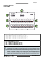
PANNELLO FRONTALE
FRONT PANEL
1. INTERRUTTORE MAGNETOTERMICO 63A
2. DISPLAY DI MONITORAGGIO DEI PARAMETRI ELETTRICI
3. INTERRUTTORI AUTOMATICI MAIN GRUPPO A (LINEE 1-6)
4. INTERRUTTORI AUTOMATICI MAIN GRUPPO B (LINEE 1-6)
5. INTERRUTTORI AUTOMATICI MAIN GRUPPO C (LINEE 1-6)
6. INTERRUTTORI AUTOMATICI MAIN GRUPPO D (LINEE 1-6)
1. 63 A THERMAL CUTOUT SWITCH
2. ELECTRICAL PARAMETERS DISPLAY
3. UNIT A MAIN CIRCUIT BREAKERS (LINES 1-6)
4. UNIT B MAIN CIRCUIT BREAKERS (LINES 1-6)
5. UNIT C MAIN CIRCUIT BREAKERS (LINES 1-6)
6. UNIT D MAIN CIRCUIT BREAKERS (LINES 1-6)

PBS-63EU
420120290Q REV.1.0
ATTENZIONE: Durante il trasporto e lo stoccaggio il range di temperatura ammesso è [-10°- 50°C]. Il quadro
elettrico deve essere sottoposto a manutenzione periodica. Effettuare la manutenzione periodica obbli-
gatoria secondo norma di legge. Osservare tutti i precetti previsti dalla normativa del proprio Paese di
utilizzo.
IMPORTANT: The ambient temperature range for transport and storage is [-10° to 50°C]. The electrical enclosure
must be serviced regularly. Run obligatory scheduled service as required by the law. Observe all applicable local
regulations.
PANNELLO POSTERIORE
REAR PANEL
7. INTERRUTTORE AUTOMATICO PRESE “SERVICE”
8. INTERRUTTORE AUTOMATICO PRESE “LINK”
9. CONNETTORE DI USCITA “SERVICE” (USCITA DI SERVIZIO) 16 A CON SPIA DI PRESENZA RETE
10. PRESE POWERCON TRUE (A - B)
11. SPIE DI PRESENZA RETE (L1, L2, L3)
12. CONNETTORI USCITE LKS (GRUPPI A - B - C - D)
13. CONNETTORE DI USCITA “LINK” (USCITA DI SERVIZIO) 32 A CON SPIA DI PRESENZA RETE
14. CORDONE DI ALIMENTAZIONE CON PRESA PENTAPOLARE DA 63 A
7. “SERVICE” SOCKET CIRCUIT BREAKER
8. “LINK” SOCKET CIRCUIT BREAKER
9. “SERVICE” OUTPUT CONNECTOR (SERVICE OUTPUT) 16 A WITH POWER LED
10. POWERCON TRUE SOCKETS (A - B)
11. POWER LEDS (L1, L2, L3)
12. LKS OUTPUT CONNECTORS (UNITS A - B - C - D)
13. “LINK” OUTPUT CONNECTOR (SERVICE OUTPUT) 32 A WITH POWER LED
14. POWER CORD WITH 5-POLE 63 A SOCKET

420120290Q REV.1.0
PBS-63EU
A.E.B. Industriale Srl Via Brodolini, 8 Località Crespellano 40053 VALSAMOGGIA BOLOGNA (ITALIA)
Tel +39 051 969870 Fax +39 051 969725 www.dbtechnologies.com [email protected]
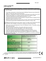
DATI TECNICI
TECH SPECS
PRIMA ACCENSIONE
FIRST TURN ON
POWERBOX PBS-63UE permette di distribuire e monitorare l’alimentazione, tramite cavi
con connettori di tipo SOCAPEX e powerCON (non forniti), a partire da una presa pentapo-
lare da 63A (trifase).
1. Prima della connessione, tutti gli interruttori di PBS-63UE devono essere disarmati. Il
quadro a monte deve essere privo di tensione.
2. Effettuare i collegamenti necessari all’impianto utilizzando le prese [8], [9], [11], [12].
3. Dopo la connessione con il cordone [13], dare tensione al quadro a monte.
4. Le spie [10] segnalano la presenza delle singole fasi L1, L2, L3.
5. Vericare la corretta tensione di alimentazione in ingresso tramite il display di visual-
izzazione [2] prima di armare le uscite.
6. Abilitare le prese necessarie [3], [4], [5], [6], [7]. entro i limiti massimi di distribuzione.
Il multimetro [2] permette di monitorare diversi parametri in tempo reale.
POWERBOX PBS-63UE distributes and monitors power via cables with SOCAPEX and power-
CON connectors (not included), connected to a 5-pole 63 A socket (three-phase).
1. Before you connect the equipment, disarm all PBS-63UE switches. The upline enclosure
must be powered off.
2. Make the required connections using sockets [8], [9], [11] and [12].
3. Hook up the power cord [13], then power on the upline enclosure.
4. The leds [10] show that the individual phases L1, L2, L3 are present.
5. Check the input power voltage on the display [2] before you arm the outputs.
6. Enable the required sockets [3], [4], [5], [6] and [7], making sure to observe the
maximum power draw limits. The multimeter [2] enables you to monitor a variety of
parameters in real time.
3+N+T
Quadro elettrico temporaneo
Temporary electrical enclosure
400V
63 A
50 Hz
3+N+GND
-
 1
1
-
 2
2
-
 3
3
-
 4
4


dBTechnologies PBS-63EU Manuale del proprietario
- Tipo
- Manuale del proprietario
in altre lingue
Altri documenti
-
Parkside PBS 900 A1 Operation and Safety Notes
-
Parkside PBS 900 C3 Translation Of The Original Instructions
-
-
-
Bosch PBS 7 A Manuale del proprietario
-
-
Bosch PBS 75A Manuale del proprietario
-
Bosch PBS75AE Manuale del proprietario
-