
ISTRUZIONI PER L’USO - NORME DI INSTALLAZIONE
INSTRUCTIONS FOR USE - DIRECTIONS FOR INSTALLATION
INSTRUCTIONS - REGLES D’INSTALLATION
INSTRUCCIONES PARA EL USO - NORMAS PARA LA INSTALACION
GEBRAUCHSANLEITUNG - ANWEISUNGEN ZUR INSTALLATION
GEBRUIKSAANWIJZINGEN – INSTALLATIEVOORSCHRIFTEN
GEO 07GEO 07
GEO 07GEO 07
GEO 07
GEO 07GEO 07
GEO 07GEO 07
GEO 07

AVVERTENZE PER L’INSTALLATORE
OBBLIGHI GENERALI PER LA SICUREZZA
1) ATTENZIONE! È importante per la sicurezza delle persone seguire
attentamente tutta l’istruzione. Una errata installazione o un errato
uso del prodotto può portare a gravi danni alle persone.
2) Leggere attentamente le istruzioni prima di iniziare l’installazione del prodot-
to.
3) I materiali dell’imballaggio (plastica, polistirolo, ecc.) non devono essere
lasciati alla portata dei bambini in quanto potenziali fonti di pericolo.
4) Conservare le istruzioni per riferimenti futuri.
5) Questo prodotto è stato progettato e costruito esclusivamente per l’utilizzo
indicato in questa documentazione. Qualsiasi altro utilizzo non espressa-
mente indicato potrebbe pregiudicare l’integrità del prodotto e/o rappre-
sentare fonte di pericolo.
6) GENIUS declina qualsiasi responsabilità derivata dall’uso improprio o diverso da
quello per cui l’automatismo è destinato.
7) Non installare l’apparecchio in atmosfera esplosiva: la presenza di gas o fumi
infiammabili costituisce un grave pericolo per la sicurezza.
8) Gli elementi costruttivi meccanici devono essere in accordo con quanto
stabilito dalle Norme EN 12604 e EN 12605.
Per i Paesi extra-CEE, oltre ai riferimenti normativi nazionali, per ottenere un
livello di sicurezza adeguato, devono essere seguite le Norme sopra ripor-
tate.
9) GENIUS non è responsabile dell’inosservanza della Buona Tecnica nella co-
struzione delle chiusure da motorizzare, nonché delle deformazioni che
dovessero intervenire nell’utilizzo.
10) L’installazione deve essere effettuata nell’osservanza delle Norme EN 12453
e EN 12445. Il livello di sicurezza dell’automazione deve essere C+D.
11) Prima di effettuare qualsiasi intervento sull’impianto, togliere l’alimentazione
elettrica e scollegare le batterie.
12) Prevedere sulla rete di alimentazione dell’automazione un interruttore
onnipolare con distanza d’apertura dei contatti uguale o superiore a 3
mm. È consigliabile l’uso di un magnetotermico da 6A con interruzione
onnipolare.
13) Verificare che a monte dell’impianto vi sia un interruttore differenziale con
soglia da 0,03 A.
14) Verificare che l’impianto di terra sia realizzato a regola d’arte e collegarvi
le parti metalliche della chiusura.
15) L’automazione dispone di una sicurezza intrinseca antischiacciamento
costituita da un controllo di coppia. E' comunque necessario verificarne
la sogli di intervento secondo quanto previsto dalle Norme indicate al punto
10.
16) I dispositivi di sicurezza (norma EN 12978) permettono di proteggere eventuali
aree di pericolo da Rischi meccanici di movimento, come ad Es. schiac-
ciamento, convogliamento, cesoiamento.
17) Per ogni impianto è consigliato l’utilizzo di almeno una segnalazione lumi-
nosa nonché di un cartello di segnalazione fissato adeguatamente sulla
struttura dell’infisso, oltre ai dispositivi citati al punto “16”.
18) GENIUS declina ogni responsabilità ai fini della sicurezza e del buon funzio-
namento dell’automazione, in caso vengano utilizzati componenti del-
l’impianto non di produzione GENIUS.
19) Per la manutenzione utilizzare esclusivamente parti originali GENIUS.
20) Non eseguire alcuna modifica sui componenti facenti parte del sistema
d’automazione.
21) L’installatore deve fornire tutte le informazioni relative al funzionamento
manuale del sistema in caso di emergenza e consegnare all’Utente utiliz-
zatore dell’impianto il libretto d’avvertenze allegato al prodotto.
22) Non permettere ai bambini o persone di sostare nelle vicinanze del prodotto
durante il funzionamento.
23) Tenere fuori dalla portata dei bambini radiocomandi o qualsiasi altro datore
di impulso, per evitare che l’automazione possa essere azionata involon-
tariamente.
24) Il transito tra le ante deve avvenire solo a cancello completamente aperto.
25) L’Utente utilizzatore deve astenersi da qualsiasi tentativo di riparazione o
d’intervento diretto e rivolgersi solo a personale qualificato.
26) Tutto quello che non è previsto espressamente in queste istruzioni non è
permesso
IMPORTANT NOTICE FOR THE INSTALLER
GENERAL SAFETY REGULATIONS
1) ATTENTION! To ensure the safety of people, it is important that you read all
the following instructions. Incorrect installation or incorrect use of the
product could cause serious harm to people.
2) Carefully read the instructions before beginning to install the product.
3) Do not leave packing materials (plastic, polystyrene, etc.) within reach of
children as such materials are potential sources of danger.
4) Store these instructions for future reference.
5) This product was designed and built strictly for the use indicated in this
documentation. Any other use, not expressly indicated here, could com-
promise the good condition/operation of the product and/or be a source
of danger.
6) GENIUS declines all liability caused by improper use or use other than that for
which the automated system was intended.
7) Do not install the equipment in an explosive atmosphere: the presence of
inflammable gas or fumes is a serious danger to safety.
8) The mechanical parts must conform to the provisions of Standards EN 12604
and EN 12605.
For non-EU countries, to obtain an adequate level of safety, the Standards
mentioned above must be observed, in addition to national legal regulations.
9) GENIUS is not responsible for failure to observe Good Technique in the
construction of the closing elements to be motorised, or for any deformation
that may occur during use.
10) The installation must conform to Standards EN 12453 and EN 12445. The safety
level of the automated system must be C+D.
11) Before attempting any job on the system, cut out electrical power and
disconnect the batteries.
12) The mains power supply of the automated system must be fitted with an
all-pole switch with contact opening distance of 3mm or greater. Use of
a 6A thermal breaker with all-pole circuit break is recommended.
13) Make sure that a differential switch with threshold of 0.03 A is fitted upstream
of the system.
14) Make sure that the earthing system is perfectly constructed, and connect
metal parts of the means of the closure to it.
15) The automated system is supplied with an intrinsic anti-crushing safety device
consisting of a torque control. Nevertheless, its tripping threshold must be
checked as specified in the Standards indicated at point 10.
16) The safety devices (EN 12978 standard) protect any danger areas against
mechanical movement Risks, such as crushing, dragging, and shearing.
17) Use of at least one indicator-light is recommended for every system, as well
as a warning sign adequately secured to the frame structure, in addition
to the devices mentioned at point “16”.
18) GENIUS declines all liability as concerns safety and efficient operation of the
automated system, if system components not produced by GENIUS are
used.
19) For maintenance, strictly use original parts by GENIUS.
20) Do not in any way modify the components of the automated system.
21) The installer shall supply all information concerning manual operation of the
system in case of an emergency, and shall hand over to the user the
warnings handbook supplied with the product.
22) Do not allow children or adults to stay near the product while it is operating.
23) Keep remote controls or other pulse generators away from children, to
prevent the automated system from being activated involuntarily.
24) Transit through the leaves is allowed only when the gate is fully open.
25) The user must not attempt any kind of repair or direct action whatever and
contact qualified personnel only.
26) Anything not expressly specified in these instructions is not permitted.
CONSIGNES POUR L'INSTALLATEUR
RÈGLES DE SÉCURITÉ
1) ATTENTION! Il est important, pour la sécurité des personnes, de suivre à la
lettre toutes les instructions. Une installation erronée ou un usage erroné
du produit peut entraîner de graves conséquences pour les personnes.
2) Lire attentivement les instructions avant d'installer le produit.
3) Les matériaux d'emballage (matière plastique, polystyrène, etc.) ne doivent
pas être laissés à la portée des enfants car ils constituent des sources
potentielles de danger.
4) Conserver les instructions pour les références futures.
5) Ce produit a été conçu et construit exclusivement pour l'usage indiqué dans
cette documentation. Toute autre utilisation non expressément indiquée
pourrait compromettre l'intégrité du produit et/ou représenter une source
de danger.
6) GENIUS décline toute responsabilité qui dériverait d'usage impropre ou différent
de celui auquel l'automatisme est destiné.
7) Ne pas installer l'appareil dans une atmosphère explosive: la présence de gaz
ou de fumées inflammables constitue un grave danger pour la sécurité.
8) Les composants mécaniques doivent répondre aux prescriptions des Normes
EN 12604 et EN 12605.
Pour les Pays extra-CEE, l'obtention d'un niveau de sécurité approprié exige
non seulement le respect des normes nationales, mais également le respect
des Normes susmentionnées.
9) GENIUS n'est pas responsable du non-respect de la Bonne Technique dans
la construction des fermetures à motoriser, ni des déformations qui pourraient
intervenir lors de l'utilisation.
10) L'installation doit être effectuée conformément aux Normes EN 12453 et EN
12445. Le niveau de sécurité de l'automatisme doit être C+D.
11) Couper l'alimentation électrique et déconnecter la batterie avant toute
intervention sur l'installation.
12) Prévoir, sur le secteur d'alimentation de l'automatisme, un interrupteur
omnipolaire avec une distance d'ouverture des contacts égale ou
supérieure à 3 mm. On recommande d'utiliser un magnétothermique de
6A avec interruption omnipolaire.
13) Vérifier qu'il y ait, en amont de l'installation, un interrupteur différentiel avec
un seuil de 0,03 A.
14) Vérifier que la mise à terre est réalisée selon les règles de l'art et y connecter
les pièces métalliques de la fermeture.
15) L'automatisme dispose d'une sécurité intrinsèque anti-écrasement, formée
d'un contrôle du couple. Il est toutefois nécessaire d'en vérifier le seuil
d'intervention suivant les prescriptions des Normes indiquées au point 10.
16) Les dispositifs de sécurité (norme EN 12978) permettent de protéger des
zones éventuellement dangereuses contre les Risques mécaniques du
mouvement, comme l'écrasement, l'acheminement, le cisaillement.
17) On recommande que toute installation soit doté au moins d'une signalisation
lumineuse, d'un panneau de signalisation fixé, de manière appropriée, sur
la structure de la fermeture, ainsi que des dispositifs cités au point “16”.
18) GENIUS décline toute responsabilité quant à la sécurité et au bon
fonctionnement de l'automatisme si les composants utilisés dans l'installation
n'appartiennent pas à la production GENIUS.
19) Utiliser exclusivement, pour l'entretien, des pièces GENIUS originales.
20) Ne jamais modifier les composants faisant partie du système d'automatisme.
21) L'installateur doit fournir toutes les informations relatives au fonctionnement
manuel du système en cas d'urgence et remettre à l'Usager qui utilise
l'installation les "Instructions pour l'Usager" fournies avec le produit.
22) Interdire aux enfants ou aux tiers de stationner près du produit durant le
fonctionnement.
23) Eloigner de la portée des enfants les radiocommandes ou tout autre
générateur d'impulsions, pour éviter tout actionnement involontaire de
l'automatisme.
24) Le transit entre les vantaux ne doit avoir lieu que lorsque le portail est
complètement ouvert.
25) L'Usager qui utilise l'installation doit éviter toute tentative de réparation ou
d'intervention directe et s'adresser uniquement à un personnel qualifié.
26) Tout ce qui n'est pas prévu expressément dans ces instructions est interdit.
ADVERTENCIAS PARA EL INSTALADOR
REGLAS GENERALES PARA LA SEGURIDAD
1) ATENCION! Es sumamente importante para la seguridad de las personas
seguir atentamente las presentes instrucciones. Una instalación incorrecta
o un uso impropio del producto puede causar graves daños a las
personas.
2) Lean detenidamente las instrucciones antes de instalar el producto.
3) Los materiales del embalaje (plástico, poliestireno, etc.) no deben dejarse al
alcance de los niños, ya que constituyen fuentes potenciales de peligro.
4) Guarden las instrucciones para futuras consultas.
5) Este producto ha sido proyectado y fabricado exclusivamente para la
utilización indicada en el presente manual. Cualquier uso diverso del

ITALIANO
1
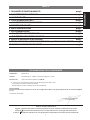
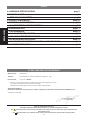
DICHIARAZIONE CE DI CONFORMITÀ
Fabbricante: GENIUS S.p.A.
Indirizzo: Via Padre Elzi, 32 - 24050 - Grassobbio- Bergamo - ITALIA
Dichiara che: L’apparecchiatura elettronica GEO 07
• è conforme ai requisiti essenziali di sicurezza delle seguenti direttive CEE:
73/23/CEE e successiva modifica 93/68/CEE.
89/336/CEE e successiva modifica 92/31/CEE e 93/68/CEE
Nota aggiuntiva:
Questo prodotto è stato sottoposto a test in una configurazione tipica omogenea (tutti prodotti di costruzione GENIUS
S.p.A.)
Grassobbio, 01-06-2006
L’Amministratore Delegato
D. Gianantoni
Note per la lettura dell'istruzione
Leggere completamente questo manuale di installazione prima di iniziare l'installazione del prodotto.
Il simbolo
evidenzia note importanti per la sicurezza delle persone e l'integrità dell'automazione.
Il simbolo richiama l'attenzione su note riguardanti le caratteristiche od il funzionamento del prodotto.
INDICE
1. PARAMETRI DI FUNZIONAMENTO pag.2
2. CARATTERISTICHE HARDWARE pag.2
3. LAY OUT SCHEDA pag.2
5. COLLEGAMENTI ELETTRICI pag.3
5.1. DESCRIZIONE COLLEGAMENTI pag.3
4. COMPONENTI SCHEDA pag.3
6. LED DI SEGNALAZIONE pag.4
7. PROGRAMMAZIONE pag.5
7.1. PROGRAMMAZIONE BASE pag.5
7.2. PROGRAMMAZIONE AVANZATA pag.5
8. VERIFICA DEL SENSO DI ROTAZIONE pag.7
9. REGOLAZIONE DELLA FRIZIONE ELETTRONICA (ANTISCHIACCIAMENTO) pag.7
10. FUNZIONAMENTO DELL’ENCODER pag.7

ITALIANO
2
12345678910
11 12
13
14
15
16
PE
N
L
J3
J5
J4
J2
J1
+
-
F
FCA
OPEN
FCC
FSWOP
ENCODER
FSWCL
F2
F1
TF1
J3
LP1
J4
F2
TF1
DL
J1
F1
J2
P3P1 P2
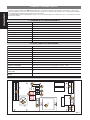
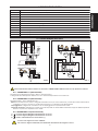
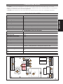
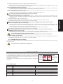
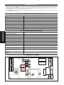
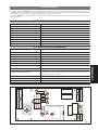
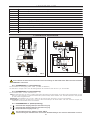
APPARECCHIATURA GEO 07
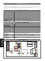
L’apparecchiatura elettrronica GEO 07 è studiata per comandare l’apertura di porte basculanti ad uno o due motori.
Grazie alla gestione di un encoder e dei finecorsa in apertura e chiusura può garantire, se correttamente installata,
un’installazione nel rispetto delle vigenti norme di sicurezza.
La scheda SLAVE, al posto dell'apparecchiatura, ha una schedina elettronica di interfaccia su cui è montata anche la
lampada di cortesia.
1. PARAMETRI DI FUNZIONAMENTO
2. CARATTERISTICHE HARDWARE
3. LAY OUT SCHEDA
acigoL acitamotuaimes/acitamotua
asuapopmeT ).nim2tluafed(.nim4a0adelibammargorp
orovalopmeT ).ces02tluafe
d(.ces95a0adelibammargorp
otnupsollaxamaippoC oN/iS
efasliaF oN/iS
oiggepmalerP ).ces0tluafed(.ces01a0adeli
bammargorp
acinortteleenoizirF illevil05uselibammargorp
asrocenifotnevretniàtiladoM otnemanoiznufideigolo
pit4
aisetrocidenoizazziropmeT ).ces03tluafed(.nim4a0adelibammargorp
ezzerucisotnevretniàtiladoM otnemano
iznufideigolopit3
enoizatnemilA zH05-CAV032
atibrossaxamaznetoP W21
irotomxamociraC W008
irosseccaenoizatnemilA cdV42
irossecca
xamociraC Am003
etneibmaarutarepmeT C°55+C°02-
enoizetorpidilibisuF irossecca/eterotiucric
odiparerottennoC
nip5oidaretneveciR
ereittesroM ilibiartse
areittesromniissergnI
asroceniF/arutrepaniezzeruciSarusuihcniez
zeruciS/redocnE/nepO
W06-CAV032erotaiggepmalarusuihcasroceniFarutrepa
areittesromnieticsU cdV42irossecca
enoizatnemilaCAV032anretseaisetrocidadapmalerotom
aisetrocadapmalxamociraC
ataroprocni
W52
aisetrocidedap
malxamociraC
enretse
W052
Abb. 1

ITALIANO
3
2
1
2
1
2
1
4
3
5
2
1
4
3
5
FSW CL
FSW OP
_
-FSW TX
FCA
FCC
FSW OP
FSW CL
OPEN
_
+
SIG.
ENCODER
1
2
3
4
5
6
7
8
9
10
J3
J1
F1
J2
230 V~
50Hz
COM
OP
CL
M
EXT. LAMP
FLASH LAMP
11 12 13 14 15
16
PE N L
MARRONE
BLU
NERO
230 V~
50Hz
COM
OP
CL
EXT. LAMP
11 12 13 14 15
16
PE N L
COM
OP
CL
6
4
5
FLASH LAMP
J1
F1
J2
M1
M2
230 V~
max.
25W
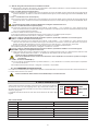
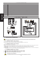
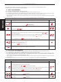
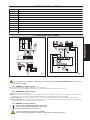
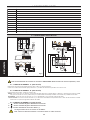
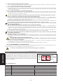
4. COMPONENTI SCHEDA
5.1. DESCRIZIONE COLLEGAMENTI
Per il funzionamento della centrale con encoder è OBBLIGATORIO utilizzare i finecorsa in apertura e chiusura
5.1.1. MORSETTIERA J1 (alta tensione)
Morsettiera per l'alimentazione 230V~ 50Hz (L= Fase N=Neutro).
Collegare la terra dell'impianto elettrico e il cavo di terra dell'operatore nel morsetto "PE".
5.1.2. MORSETTIERA J2 (alta tensione)
Morsettiera 230V~ per il collegamento di:
Motore: ai morsetti OP e CL vanno collegate le fasi del motore (cavi Nero e Marrone), mentre al morsetto COM si deve
collegare il comune (cavo Blu).Il condensatore di spunto va collegato in parallelo alle fasi.
Lampeggiatore: collegare tra i morsetti 15 e 16 un lampeggiatore con potenza max. 60W.
Lampada di cortesia: collegare tra i morsetti 14 e 16 la lampada di cortesia della scheda SLAVE oppure delle lampade di
esterne con potenza complessiva max. 250W.
5.1.3. MORSETTIERA J3 (bassa tensione)
1 = = Comune ingressi/Negativo alimentazione accessori
2 = = Comune ingressi/Negativo alimentazione accessori
3 = = Positivo alimentazione accessori 24Vdc (+)
Il carico max degli accessori è di 300mA .
Per il calcolo degli assorbimenti, fare riferimento alle istruzioni dei singoli accessori.
5. COLLEGAMENTI ELETTRICI
1F )eterotiucric(V052/A502x51FelibisuF
2F )irossecca(V052/Am00502x52FelibisuF
1FT erotamrofsarT
1PL 41EV022W
52aisetrocidadapmaL
LD yalpsiD
1J CAV032enoizatnemilaossergniareittesroM
2J .txeaisetroc.pmaleerotaiggepmal
,erotomaticsuareittesroM
3J irossecca/issergnienoisnetassabareittesroM
4J itneveciredehcsodiparerottennoC
1P "enoizammargorpidetnasluP +"
2P "enoizammargorpidetnasluP -"
3P "enoizammargorpidetnasluP F"
Abb. 2
Abb. 3

ITALIANO
4
FCA
OPEN
FCC
FSWOP
ENCODER
FSWCL
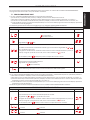
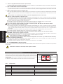
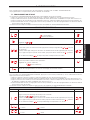
4 = -FSW TX = Negativo alimentazione trasmettitori fotocellule
Il collegamento separato del negativo dei trasmettitori, permette di utilizzare il controllo Failsafe sulle fotocellule,
aumentando il livello di sicurezza dell'impianto.
5 = FCA = Contatto Finecorsa apertura (N.C.)
Il finecorsa di apertura è costituito da un micropulsante che, azionato dalla camma quando la porta raggiunge la
posizione di aperto, arresta il movimento immediatamente oppure, in base alla programmazione effettuata, dopo
3 sec.
6 = FCC = Contatto Finecorsa chiusura (N.C.)
Il finecorsa di chiusura è costituito da un micropulsante che, azionato dalla camma quando la porta raggiunge la
posizione di chiuso, arresta il movimento immediatamente oppure, in base alla programmazione effettuata, dopo
3 sec.
Per il funzionamento della centrale è obbligatorio collegare entrambi i finecorsa.
7 = FSW OP = Contatto Sicurezze in Apertura (N.C.)
Per sicurezze si intendono tutti i dispositivi (fotocellule, coste sensibili, ...) con contatto N.C. che in presenza di un
ostacolo nell’area da loro protetta, intervengono arrestando o invertendo il movimento di apertura della porta (vedi
cap. 7.2- Programmazione avanzata).
Non hanno effetto durante la fase di chiusura.
Le sicurezze in apertura, se impegnate a porta chiusa, inibiscono qualsiasi impulso di Open.
Per installare più dispositivi di sicurezza, collegare i contatti N.C. in serie.
Se non vengono collegati dispositivi di sicurezza in apertura, ponticellare "FSW OP" col Comune ingressi.
8 = FSW CL = Contatto Sicurezze in Chiusura (N.C.)
Per sicurezze si intendono tutti i dispositivi (fotocellule, coste sensibili, ...) con contatto N.C. che in presenza di un
ostacolo nell’area da loro protetta, intervengono invertendo il movimento di chiusura della porta. Non hanno
effetto durante la fase di apertura, escluso in funzione Ad (vedi cap. 5.3.1.- Programmaz. avanzata).
Le sicurezze in chiusura, se impegnate a porta aperta, inibiscono qualsiasi impulso di Open.
Per installare più dispositivi di sicurezza, collegare i contatti N.C. in serie.
Se non vengono collegati dispositivi di sicurezza in chiusura, ponticellare "FSW CL" col Comune ingressi.
9 = ENCODER = Ingresso per il segnale dell’encoder
A questo morsetto deve essere collegato il segnale provveniente dall’encoder. Per l’alimentazione dell’encoder
collegare i restanti due fili ai morsetti “1 - 3” rispettando la polarità indicata sulla scheda.
Senza encoder la centrale non funziona
Nel caso di apllicazioni a due motori l’encodere deve essere applicato solo al motore 1 (quello con l’appa-
recchiatura)
10 = OPEN = Comando di OPEN (N.A.)
Viene così indicato qualsiasi dispositivo (pulsante, detector,..) che, chiudendo un contatto, dà un impulso d’apertura
(o chiusura) alla porta.
Per installare più dispositivi di Open, collegare i contatti N.A. in parallelo.
5.1.4. CONNETTORE J4 (bassa tensione)
Il connettore J4 è utilizzato per il collegamento rapido di schede RICEVENTI. La scheda ricevente deve essere innestata con
i componenti rivolti verso la scheda.
Innesto e disinnesto della scheda vanno effettuati dopo aver tolto tensione.
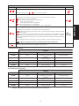
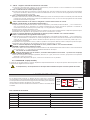
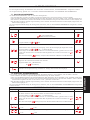
6. LED DI SEGNALAZIONE
Sulla scheda è presente un display a due cifre che, durante il normale fun-
zionamento, indica lo stato degli ingressi. In fig.4 è indicata l'esatta corri-
spondenza tra i segmenti orizzontali (che d'ora in poi chiameremo Led) del
display e gli ingressi.
La tabella sottostante riporta lo stato dei Led in relazione allo stato degli
ingressi.
TAB.1 STATO DEI LED
DEL OSECCA OTNEPS
NEPO ovittaarutrepaodnamoc ovittaniarutrepaodnamoc
REDOCNE otnemanoiznuflietnarudetnaiggepmaldeL
POW
SF etangepmisidarutrepaniezzerucis etangepmiarutrepaniezzerucis
LCWSF etangepmisidarusuihcniezzerucis etan
gepmiarusuihcniezzerucis
ACF orebilarutrepaasrocenif otapuccoarutrepaasrocenif
CCF orebilarusuihcasrocenif
otapuccoarusuihcasrocenif
=oseccadeL /osuihcottatnoc =otnepsdeL otrepaottatnoc
Abb. 4

ITALIANO
5
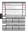
7. PROGRAMMAZIONE
Per programmare il funzionamento dell'automazione è necessario accedere alla modalità "PROGRAMMAZIONE".
La programmazione si divide in due parti: BASE e AVANZATA.
7.1. PROGRAMMAZIONE BASE
L'accesso alla PROGRAMMAZIONE BASE avviene tramite il pulsante F:
• premendolo (e mantenendolo premuto) il display mostra il nome della prima funzione.
• rilasciando il pulsante, il display visualizza il valore della funzione che può essere modificato con i tasti + e -.
• premendo nuovamente F (e mantenendolo premuto) il display mostra il nome della funzione successiva, ecc.
• arrivati all'ultima funzione, la pressione del pulsante F provoca l'uscita dalla programmazione ed il display riprende a
visualizzare lo stato degli ingressi.
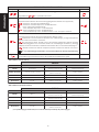
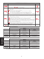
La tabella seguente indica la sequenza delle funzioni accessibili in PROGRAMMAZIONE BASE:
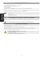
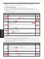
PROGRAMMAZIONE AVANZATA
Display
Funzione
Default
ILLUMINAZIONE DI CORTESIA:
Imposta il tempo di accensione della lampada di cortesia.
Regolabile da
a sec. a passi di un secondo.
In seguito la visualizzazione cambia in minuti e decine di secondi (separati da un punto) e
il tempo si regola a passi di 10 secondi, fino al valore massimo di
minuti.
ES: se il display indica
, il tempo di accensione corrisponde a 2 min. e 50 sec.
COPPIA MASSIMA ALLO SPUNTO:
= Attiva = Esclusa
FAIL SAFE (verifica funzionamento sicurezze):
= Attivo = Escluso
PROGRAMMAZIONE BASE
Display
Funzione
Default
LOGICHE DI FUNZIONAMENTO:
= Automatica
= Semiautomatica
PARTENZA RALLENTATA IN CHIUSURA:
Regolabile da
a sec.
TEMPO DI PAUSA:
Ha effetto solamente se è stata selezionata la logica automatica. Regolabile da
a
sec. a passi di un secondo.
In seguito la visualizzazione cambia in minuti e decine di secondi (separati da un punto) e
il tempo si regola a passi di 10 secondi, fino al valore massimo di
minuti.
ES: se il display indica
, il tempo di pausa corrisponde a 2 min. e 50 sec.
FRIZIONE ELETTRONICA:
Limita la spinta massima dell'operatore.
Regolabile da
(forza minima)
a (forza massima)
Uscita dalla programmazione e ritorno alla visualizzazione dello stato ingressi.
7.2. PROGRAMMAZIONE AVANZATA
Per accedere alla PROGRAMMAZIONE AVANZATA premere il pulsante F e, mantenendolo premuto, premere il pulsante +:
• rilasciando il pulsante + il display mostra il nome della prima funzione.
• rilasciando anche il pulsante F, il display visualizza il valore della funzione che può essere modificato con i tasti + e -.
• premendo il tasto F (e mantenendolo premuto) il display mostra il nome della funzione successiva, rilasciandolo viene
visualizzato il valore che può essere modificato con i tasti + e -.
• arrivati all'ultima funzione, la pressione del pulsante F provoca l'uscita dalla programmazione ed il display riprende a
visualizzare lo stato degli ingressi.
La tabella seguente indica la sequenza delle funzioni accessibili in PROGRAMMAZIONE AVANZATA:

ITALIANO
6
PROGRAMMAZIONE AVANZATA
Display
Funzione
Default
MODALITA' INTERVENTO SICUREZZE:
Imposta il funzionamento del motore all'impegno delle sicurezze:
= FSWOP blocca il movimento di apertura che, al disimpegno, prosegue in apertura.
FSWCL inverte il movimento di chiusura.
= A basculante chiusa, aperta o bloccata e FSWCL impegnata, l'impulso di Open
attiva il lampeggiatore e il movimento inizia solo al disimpegno di FSWCL
(1)
(funzione
ADMAP). Durante il movimento, FSWOP inverte e FSWCL blocca e inverte al disimpegno
(1)
.
= FSWOP inverte il movimento di apertura, FSWCL inverte il movimento di chiusura.
(1)
Con prelampeggio selezionato, il movimento inizia dopo il tempo di prelampeg-
gio.
PRELAMPEGGIO del lampeggiatore:
Regolabile da
a sec. a passi di un secondo.
MODALITA' INTERVENTO FINECORSA:
Imposta il funzionamento del motore al raggiungimento dei finecorsa (opzionali):
=FCA/FCC: Si arresta immediatamente
=FCA/FCC: Si arresta dopo 3 sec. di rallentamento
=FCA: Si arresta immediatamente
FCC: Si arresta dopo 3 sec. a velocità piena
=FCA: Si arresta dopo 3 sec. di rallentamento
FCC:Si arresta dopo 2 sec. di rallentamento + 1 sec. di colpo in chiusura
Uscita dalla programmazione e ritorno alla visualizzazione dello stato ingressi.
TAB.2 LOGICA A (Automatica)
TAB.3 LOGICA E (Semiautomatica)
(1)
Con prelampeggio selezionato, il movimento inizia dopo il tempo di prelampeggio.
ISLUPMI
ATROPOTATS NEPO ARUSUIHCEZZERUCIS ARUTREPAEZZERUCIS
ASUIHC
opmetliopodeduihcireerpa
asuapid
)1(
otteffenussen
)dAenoiznufosulcse(
otteffenussen
)arutrepaecsibini(
ASUAPNIATREPA asuapopmetliatnocir
otteff
enussen
)arusuihcecsibini(
otteffenussen
ARUSUIHCNI otomlietrevniotomlietrevniotteffenussen
ARUTREPANI otteff
enussenotteffenussenenoizammargorPidev
ATACCOLB eduihc
)1(
otteffenussen
)arusuihcecsibini(
otteffenussen
ISLUPMI
ATROPOTATS NEPO ARUSUIHCEZZERUCIS ARUTREPAEZZERUCIS
ASUIHC erpa
)1(
otteffenussen
)dAenoiznufosulcse(
otteffenussen
)arutrepaecsibini(
ASUAPNIATREPA eduihc
)1(
otteffenussen
)dAenoiznufosulcse(
otteffenussen
ARUSUIHCNI otomlietrevniotomlietrevniotteffenussen
ARUTREPAN
I accolbotteffenussenenoizammargorPidev
ATACCOLB eduihc
)1(
otteffenussen
)arusuihcecsibini(
otteffenussen

ITALIANO
7
8. VERIFICA DEL SENSO DI ROTAZIONE
Per controllare l’esatto collegamento delle fasi del motore è necessario eseguire le seguente procedura:
1) Predisporre l’operatore per il funzionamento manuale
2) Portare manualmente la porta a metà apertura.
3) Bloccare l'operatore
4) Alimentare il sistema.
5) Inviare un impulso di apertura (OPEN) e verificare che il motore esegua un'apertura della porta.
Nel caso si verifichi una chiusura, è necessario invertire sulla morsettiera della scheda le fasi del motore elettrico (cavi
marrone e nero).
Nell'applicazione con due operatori, ai morsetti "COM,OP,CL", della scheda e della scheda Slave, assegnare la stessa
colorazione dei cavi e, dovendo invertire le fasi, invertirle per entrambi i motori.
• La scheda esegue un controllo elettronico (che richiede la presenza del motore collegato) prima di ogni
partenza. Se si tenta di far funzionare la scheda senza il carico del motore o con un carico insufficiente, non
viene fornita tensione sull'uscita motore.
• La luce di cortesia si attiva alla partenza del motore e rimane accesa, a partire dal termine del movimento,
per il tempo programmato.
9. REGOLAZIONE DELLA FRIZIONE ELETTRONICA (ANTISCHIACCIAMENTO)
L’apparecchiatura è fornita di un sistema elettronico di regolazione della coppia del motore che, in funzione della rego-
lazione stessa, limita la spinta della porta in presenza di un ostacolo. Alla rimozione dell’ostacolo la porta prosegue il proprio
movimento sino al raggiungimento del finecorsa o della battuta meccanica.
Si raccomanda di tarare la frizione elettronica in conformità alle vigenti norme di sicurezza.
10. FUNZIONAMENTO DELL’ENCODER
Grazie alla gestione dell’encoder la centrale di comando GEO 07 può di garantire, se correttamente installata, un’istallazione
conforme alle vigenti norme di sicurezza.
L’encoder è attivo sia durante la fase d’apertura sia durante la fase di chiusura della porta.
Durante la fase d’apertura l’encoder interviene bloccando il movimento della porta e posizionando la centrale in STOP.
Al primo comando di apertura la porta esegue una manovra di chiusura e riprende il ciclo di lavoro memorizzato.
Durante la fase di chiusura l’encoder interviene invertendo il moto della porta fino alla completa apertura della stessa. Se
si stà lavorando con una logica automatica la porta si richiuderà allo scadere del tempo dipausa.
• L’intervento dell’encoder NON DISABILITA la richiusura automatica.
• L’encoder viene disattivato dall’intervento di uno dei due finecorsa, permettendo alla porta il riconoscimento
della battuta meccanica.
• La sensibilità di rilevamento dell’ostacolo è legata alla regolazione di coppia del motore, più si aumenta la
forza del motore più si abbassa la sensibilità di rilevamento dell’encoder e viceversa.

ENGLISH
8
CE DECLARATION OF CONFORMITY
Manufacturer: GENIUS S.p.A.
Address: Via Padre Elzi, 32 - 24050 - Grassobbio- Bergamo - ITALY
Declares that: control unit GEO 07
• conforms to the essential safety requirements of the following EEC directives:
73/23/EEC and subsequent amendment 93/68/EEC.
89/336/EEC and subsequent amendment 92/31/EEC and 93/68/EEC
Additional information:
This product underwent a test in a typical, uniform configuration (all products manufactured by GENIUS S.p.A.).
Grassobbio, 01-06-2006
The Managing Director
D. Gianantoni
Notes on reading the instruction
Read this installation manual to the full before you begin installing the product.
The symbol indicates notes that are important for the safety of persons and for the good condition of the
automated system
The symbol draws your attention to the notes on the characteristics and operation of the product.
INDEX
2. HARDWARE SPECIFICATIONS pag.9
3. BOARD LAY-OUT pag.9
1. OPERATING PARAMETERS pag.9
4. BOARD COMPONENTS pag.10
5. ELECTRICAL CONNECTIONS pag.10
5.1. DESCRIPTION OF CONNECTIONS pag.10
6. SIGNALLING LEDs pag.11
7. PROGRAMMING pag.12
7.1. BASIC PROGRAMMING pag.12
7.2. ADVANCED PROGRAMMING pag.12
8. ROTATION DIRECTION CHECK pag.14
9. ADJUSTMENT OF ELECTRONIC CLUTCH (ANTI-CRUSHING) pag.14
10. ENCODER OPERATION pag.14

ENGLISH
9
12345678910
11 12
13
14
15
16
PE
N
L
J3
J5
J4
J2
J1
+
-
F
FCA
OPEN
FCC
FSWOP
ENCODER
FSWCL
F2
F1
TF1
J3
LP1
J4
F2
TF1
DL
J1
F1
J2
P3P1 P2
cigoL citamotua-imes/citamotua
emitesuaP ).nim2tluafed(.nim4ot0morfelbammargorp
emitkroW ).ces02tluafed(.c
es95ot0morfelbammargorp
euqrotgnitratsxaM oN/seY
efaSliaF oN/seY
gnihsalf-erP ).ces0tluafed(.ces01ot0morfel
bammargorp
hctulccinortcelE slevel05noelbammargorp
edomnoitnevretnihctiws-timiL sedomgnitarepofosepyt4
gni
mitysetruoC ).ces03tluafed(.nim4ot0morfelbammargorp
edomnoitnevretnisecivedytefaS sedomgnitarepofosepyt3
ylppusrewoP zH05-CAV032
rewopdebrosba.xaM W21
daol.xamsrotoM W008
seirosseccarofylppusrewoP cdV42
daol.xamsei
rosseccA Am003
erutarepmettneibmagnitarepO C°55+C°02-
sesuFevitcetorP tiucricseirossecca/sniam
gulpdipaR rev
ieceroidarnip5
sdraoblanimreT elbavomer
stupnidraoblanimreT
gninepO/secivedytefasgninepO/secivedytefasgni
solC/redocnE/nepO
W06-CAV032pmalgnihsalf/hctiws-timilgnisolC/hctiws-timil
stuptuodraoblanimreT cdV42seir
osseccaylppusrewopCAV032thgilysetruoclanretxerotom
ysetruocdetargetnirofdaol.xaM
thgil
W52
ysetruoclanret
xerofdaol.xaM
sthgil
W052
CONTROL UNIT GEO 07
The GEO 07 control unit was designed to command the opening of up-and-over doors with one or two motors.
Thanks to management by encoder and opening and closing limit-switches, if correctly installed, it can guarantee
installation in conformity with current safety regulations.
The SLAVE board, instead of the unit, has an electronic interface board on which the courtesy light is also fitted.
1. OPERATING PARAMETERS
2. HARDWARE SPECIFICATIONS
3. BOARD LAY-OUT
Fig. 1

ENGLISH
10
2
1
2
1
2
1
4
3
5
2
1
4
3
5
FSW CL
FSW OP
_
-FSW TX
FCA
FCC
FSW OP
FSW CL
OPEN
_
+
SIG.
ENCODER
1
2
3
4
5
6
7
8
9
10
J3
J1
F1
J2
230 V~
50Hz
COM
OP
CL
M
EXT. LAMP
FLASH LAMP
11 12 13 14 15
16
PE N L
MARRONE
BLU
NERO
230 V~
50Hz
COM
OP
CL
EXT. LAMP
11 12 13 14 15
16
PE N L
COM
OP
CL
6
4
5
FLASH LAMP
J1
F1
J2
M1
M2
230 V~
max.
25W
1F )tiucricsniam(V052/A502x51FesuF
2F )seirossecca(V052/Am00502x52FesuF
1FT remrofsnarT
1PL 41EV022W52thgily
setruoC
LD yalpsiD
1J draoblanimrettupniylppusrewopCAV032
2J thgilysetruoc.txednapmalgnihsalf,rotom:draob-l
animrettuptuO
3J draoblanimretseirossecca/stupniegatlovwoL
4J rotcennocdiparsdraobrevieceR
1P "nottub-hsupg
nimmargorP +"
2P "nottub-hsupgnimmargorP -"
3P "nottub-hsupgnimmargorP F"
4. BOARD COMPONENTS
5. ELECTRICAL CONNECTIONS
5.1. DESCRIPTION OF CONNECTIONS
For operation of the control unit with the encoder, the opening and closing limit-switches MUST be used.
5.1.1. TERMINAL BOARD J1 (high voltage)
Terminal board for 230V~ 50Hz (L= Phase N=Neutral) power supply.
Connect earth of electrical system and earth cable of the operator to terminal "PE".
5.1.2. TERMINAL BOARD J2 (high voltage)
230V~ Terminal board for connection of:
Motor: connect the motor phases (Black and Brown cables) to the OP and CL terminals. Connect the common contact
(Blue cable) to terminal COM. Connect the starting capacitor in parallel with respect to the phases.
Flashing lamp: connect the flashing lamp with max. 60W power supply between terminals 15 and 16.
Courtesy light: connect the courtesy light of the SLAVE board between terminals 14 and 16, or connect the external
courtesy lights with overall power of 250W between these terminals.
5.1.3. TERMINAL BOARD J3 (low voltage)
1 = = Inputs common contact /Negative pole for accessories supply
2 = = Inputs common contact /Negative pole for accessories supply
3 = = Positive pole for powering 24 Vdc (+) accessories
Accessories max. load: 300 mA.
To calculate absorption values, refer to the instructions for individual accessories.
Fig. 2
Fig. 3

ENGLISH
11
FCA
OPEN
FCC
FSWOP
ENCODER
FSWCL
DEL NO FFO
NEPO evitcadnammocgninepo evitcanidnammocgninepo
REDOCNE noitarepognirudsehsalfDEL
POWSF degagnesidseciv
edytefasgninepo degagnesecivedytefasgninepo
LCWSF degagnesidsecivedytefasgnisolc degagneecivedytefasgniso
lc
ACF eerfhctiws-timilgninepo degagnehctiws-timilgninepo
CCF eerfhctiws-timilgnisolc degagnehctiws-timilgn
isolc
=NODEL /tcatnocdesolc =FFODEL tcatnocnepo
4 = -FSW TX = Negative pole for power supply to photocell transmitters
Separate connection of the negative pole of the transmitters makes it possible to use the Failsafe control on the
photocells, thus increasing the system's safety level.
5 = FCA = Opening Limit-switch contact (N.C.)
The opening limit-switch consists of a micro-pushbutton which, activated by the cam when the door reaches open
position, stops movement immediately or, according to programming, after 3 sec.
6 = FCC = Closing Limit-switch contact (N.C.)
The closing limit-switch consists of a micro-pushbutton which, activated by the cam when the door reaches closed
position, stops movement immediately or, according to programming, after 3 sec.
For control unit operation, both limit-switches must be connected.
7 = FSW OP = Opening Safety Devices contact (N.C.)
Safety devices are all devices (photocells, sensitive edges,…) with N.C. contact, which, if there is an obstacle in the
area they protect, operate by stopping or reversing the door opening movement (see chap.7.2 - Advanced
programming).
They have no effect during the closing stage.
If the opening safety devices are engaged while the door is closed, they inhibit any Open pulse.
To install several safety devices, connect the N.C. contacts in series.
If no opening safety devices are connected, jumper connect "FSW OP" to the inputs common contact.
8 = FSW CL = Closing Safety Devices contact (N.C.)
Safety devices are all devices (photocells, sensitive edges,…) with N.C. contact, which, if there is an obstacle in the
area they protect, operate to reverse door closing movement. They have no effect during the opening stage, except
in the Ad function (see chap.5.3.1. - Advanced programming).
If the closing safety devices are engaged while the door is open, they inhibit any Open pulse.
To install several safety devices, connect the N.C. contacts in series.
If no closing safety devices are connected, jumper connect "FSW CL" to the inputs common contact.
9 = ENCODER = Input for encoder signal
The signal received from the encoder must be connected to this terminal. To supply power to the encoder, connect
the remaining two wires to terminals “1 - 3” observing the polarity indicated on the board.
The control unit will not operate without an encoder
For two-motor applications, the encoder must be applied only to motor 1 (the one with the unit)
10 = OPEN = OPEN Command (N.O.)
Any device (push-button, detector,…) which, by closing a contact, supplies an opening (or closing) pulse to the door.
To install several Open devices, connect N.O. contacts in parallel.
5.1.4. CONNECTOR J4 (low voltage)
Connector J4 is used for rapid connection of RECEIVING boards. The receiver board must be inserted with the components
facing the board.
Insert and remove the boards after cutting power.
6. SIGNALLING LEDs
A two-digit display is installed on the board. During normal operation, it
indicates the status of the inputs. Fig.4 shows the exact correspondence
between the horizontal segments (we will call them LEDs from now on) of
the display and the inputs.
The table below indicates the status of the LEDs in relation to the status of
the inputs.
TAB.1 STATUS OF LEDS
Fig. 4

ENGLISH
12
BASIC PROGRAMMING
Display
Function
Default
FUNCTION LOGICS:
= Automatic
= Semi-automatic
CLOSING SLOW START:
Settable from to sec.
PAUSE TIME:
This operates only if the automatic logic was selected. Can be adjusted from to sec.
in one second steps.
Next, the viewing changes in minutes and tenths of a second (separated by a dot) and time
is adjusted in 10 second steps, up to the maximum value of minutes.
E.g.: if the display shows , the pause time will be 2 min and 50 sec.
ELECTRONIC CLUTCH:
Limits the operator's maximum thrust.
Settable from (minimum force)
to (maximum force)
To exit programming and return to display of inputs status
ADVANCED PROGRAMMING
Display
Function
Default
COURTESY LIGHT:
For setting lighted time of the courtesy light.
Can be adjusted from to sec. in one second steps.
Next, the viewing changes in minutes and tenths of a second (separated by a dot) and time
is adjusted in 10 second steps, up to the maximum value of minutes.
E.g.: if the display shows , the lighted time will be 2 min and 50 sec.
MAXIMUM STARTING TORQUE:
= Active = Disabled
FAIL SAFE (safety devices operational check):
= Active = Disabled
7. PROGRAMMING
To program the operation of the automated system, you must access the "PROGRAMMING" mode.
Programming is in two parts: BASIC and ADVANCED.
7.1. BASIC PROGRAMMING
To access BASIC PROGRAMMING, use push-button F:
• if you press it (and hold it down), the display shows the name of the first function.
• if you release the push-button, the display shows the value of the function, which can be changed with keys + and -.
• if you press F again (and hold it down), the display shows the name of the next function, etc.
• when you reach the last function, press the F push-button to exit programming, and the display resumes showing the
inputs status.
The following table indicates the sequence of functions accessible in BASIC PROGRAMMING:
7.2. ADVANCED PROGRAMMING
To access ADVANCED PROGRAMMING, press push-button F and, while holding it down, press push-button +:
• if you release the + push-button, the display shows the name of the first function.
• if you also release the F push-button, the display shows the value of the function, which can be changed with keys + and -.
• if you press the F push-button (and hold it down), the display shows the name of the next function; if you release it, the
value is shown and can be changed with keys + and -.
• when you reach the last function, press the F push-button to exit programming, and the display resumes showing the
inputs status.
The following table indicates the sequence of functions accessible in ADVANCED PROGRAMMING:

ENGLISH
13
ADVANCED PROGRAMMING
Display
Function
Default
PRE-FLASHING of flashing lamp:
Can be adjusted from to sec. in one second steps.
LIMIT-SWITCH INTERVENTION MODE:
For setting motor operation when limit-switches (optionals) are reached:
=FCA/FCC: Stops immediately
=FCA/FCC: Stops after 3 sec. deceleration
=FCA: Stops immediately
FCC: Stops after 3 sec. at full speed
=FCA: Stops after 3 sec. deceleration
FCC: Stops after 2 sec. deceleration +1 sec. closing thrust
SAFETY DEVICES INTERVENTION MODE:
For setting motor operation when safety devices are engaged
= FSWOP stops opening movement which, on release, resumes opening. FSWCL reverses
closing movement.
= When up-and-over door is closed, open or locked and FSWCL are engaged, the Open
pulse activates the flashing lamp and movement begins only when FSWCL
(1)
(ADMAP
function) disengages. During the movement, FSWOP reverses, and FSWCL stops and reverses
on release
(1)
.
= FSWOP reverses the opening movement, FSWCL reverses closing movement.
(1)
With pre-flashing selected, movement begins after pre-flashing time.
To exit programming and return to display of inputs status
SESLUP
SUTATSROOD NEPO SECIVEDYTEFASGNISOLC SECIVEDYTEFASGNINEPO
DESOLC
esuapretfasesolcdnasnepo
emit
)1(
tceffeon
)noitcnufdAgnidulcxe(
tceffeon
)gninepostibihni(
ESUAPNINEPO emitesuapstnuoc-er
tceffeon
)gnisolcst
ibihni(
tceffeon
GNISOLC noitomsesrevernoitomsesrevertceffeon
GNINEPO tceffeontceffeongnimmargorPees
DEPPOTS ses
olc
)1(
tceffeon
)gnisolcstibihni(
tceffeon
SESLUP
SUTATSROOD NEPO SECIVEDYTEFASGNISOLC SECIVEDYTEFASGNINEPO
DESOLC snepo
)1(
tceffeon
)noitcnufdAgnidulcxe(
tceffeon
)gninepostibihni(
ESUAPNINEPO sesolc
)1(
tceffeon
)noitcnufdAgnidulcxe(
tceffeon
GNISOLC noitomsesrevernoitomsesrevertceffeon
GNINEPO spotstceffeongnimm
argorPees
DEPPOTS sesolc
)1(
tceffeon
)gnisolcstibihni(
tceffeon
TAB.2 LOGIC A (Automatic)
TAB.3 LOGIC E (Semi-automatic)
(1)
With pre-flashing selected, movement begins after pre-flashing time.

ENGLISH
14
8. ROTATION DIRECTION CHECK
Procedure for checking exact connection of motor phases:
1) Put the operator in manual mode
2) Manually take the door to its operating mid-point.
3) Stop the operator
4) Power up the system.
5) Send an opening pulse (OPEN) and check if the motor executes a door opening operation.
If the door closes, change over the phases of the electric motor on the terminal-board (black and brown cables) of the
board.
For two-operator applications, assign the same wire colours to the "COM,OP,CL" terminals, of the board and the Slave board,
and, if you have to change over the phases, change them over for both motors.
• The board carries out an electronic control (the connected motor must be present) before every start. If you
attempt to make the board operate without motor load or with an insufficient load, no power is supplied
at motor output.
• The courtesy light lights up when the motor starts and remains lighted for the programmed time, starting when
the movement has finished.
9. ADJUSTMENT OF ELECTRONIC CLUTCH (ANTI-CRUSHING)
The unit has a motor torque adjustment electronic system which, according to the setting, limits door thrust in the presence
of an obstacle. When the obstacle is removed, the door resumes moving until it reaches the limit-switch or the mechanical
stop.
We advise you to adjust the electronic clutch in conformity with current safety regulations.
10. ENCODER OPERATION
Thanks to encoder management, the GEO 07 control unit, if correctly installed, guarantees installation in compliance with
current safety regulations.
The encoder is active during both door opening and closing stages.
During the opening stage, the encoder stops door movement and positions the control unit in STOP status. At the first
opening command, the door executes a closing operation and resumes the memory-stored work cycle.
During the closing stage, the encoder reverses door motion until the door is completely open. If operating with an automatic
logic, the door closes when pause time has elapsed.
• Encoder intervention DOES NOT DISABLE automatic re-closing.
• The encoder is disabled by the intervention of one of the two limit-switches, enabling the door to recognise
the mechanical travel stop.
• Obstacle detection sensitivity is linked to the motor torque setting: the more motor power is increased, the
lower the encoder's detection sensitivity and vice-versa.

FRANÇAIS
15
DÉCLARATION CE DE CONFORMITÉ
Fabricant : GENIUS S.p.A.
Adresse : Via Padre Elzi, 32 - 24050 - Grassobbio- Bergamo - ITALIE
Déclare que : L’armoire électronique GEO 07
• est conforme aux exigences essentielles de sécurité des directives CEE suivantes :
73/23/CEE et modification 93/68/CEE successive.
89/336/CEE et modifications 92/31/CEE et 93/68/CEE successives.
Note complémentaire:
Ce produit a été testé dans une configuration typique homogène (tous les produits sont fabriqués par GENIUS S.p.A.)
Grassobbio, le 01-06-2006
L’Administrateur Délégué
D. Gianantoni
Remarques pour la lecture de l’instruction
Lire ce manuel d’installation dans son ensemble avant de commencer l’installation du produit.
Le symbole
souligne des remarques importantes pour la sécurité des personnes et le parfait état de l’automatisme.
Le symbole
attire l'attention sur des remarques concernant les caractéristiques ou le fonctionnement du produit.
CONTENENTS
1. PARAMÈTRES DE FONCTIONNEMENT pag.16
2. CARACTÉRISTIQUES DU MATÉRIEL pag.16
3. SCHÉMA DE LA CARTE pag.16
4. COMPOSANTS DE LA CARTE pag.17
5. CONNEXIONS ÉLECTRIQUES pag.17
5.1. DESCRIPTION DES CONNEXIONS pag.17
6. LEDs DE SIGNALISATION pag.18
7. PROGRAMMATION pag.19
7.1. PROGRAMMATION DE BASE pag.19
7.2. PROGRAMMATION AVANCÉE pag.19
8. CONTRÔLE DU SENS DE ROTATION pag.21
9. RÉGLAGE DE L’EMBRAYAGE ÉLECTRONIQUE (ANTI-ÉCRASEMENT) pag.21
10. FONCTIONNEMENT DE L’ENCODEUR pag.21

FRANÇAIS
16
12345678910
11 12
13
14
15
16
PE
N
L
J3
J5
J4
J2
J1
+
-
F
FCA
OPEN
FCC
FSWOP
ENCODER
FSWCL
F2
F1
TF1
J3
LP1
J4
F2
TF1
DL
J1
F1
J2
P3P1 P2
euqigoL euqitamotua-imes/euqitamotua
esuapedspmeT )tuafédrapnm2(nm4à0edelbammargorp
tnemennoitcnofedspmeT
)tuafédraps02(s95à0edelbammargorp
egarraméduaixamelpuoC noN/iuO
efasliaF noN/iuO
tnemetongilcérP )tuafédrap
s0(s01à0edelbammargorp
euqinortceléegayarbmE xuaevin05ruselbammargorp
esruocedsnifnoitnevretni’détiladoM
tnemennoitcnofedsepyt4
eisiotruocedegarialcénoitasiropmeT )tuafédraps03(nm4à0edelbammargorp
sétirucésnoi
tnevretni’détiladoM tnemennoitcnofedsepyt3
noitatnemilA zH05~ACV032
eébrosbaixamecnassiuP W21
sruetomixamegrahC W008
seriosseccanoitatnemilA ccV42
serio
sseccaixamegrahC Am003
tnemennoitcnofederutarépmeT C°55+C°02-
noitcetorpedselbisuF seriossecca/uaesértiucr
iC
ediparruetcennoC sehcorb5oidarruetpecéR
sreinroB selbivoma
reinrobseértnE
edniF/erutrevuonesétirucéS/eru
temrefnesétirucéS/ruedocnE/nepO
W06-ACV032etnatongilcepmal/erutemrefesruocedniF/erutrevuoesruoc
reinrob
seitroS ccV42seriosseccanoitatnemilaACV032enretxeeisiotruocedepmalruetom
eisiotruocedepmalixamegrahC
eér
oprocni
W52
eisiotruocedsepmalixamegrahC
senretxe
W052
ARMOIRE GEO 07
L’armoire électronique GEO 07 est conçue pour commander l’ouverture de portes basculantes à un ou deux moteurs.
Grâce à la gestion d’un encodeur et des fins de course en ouverture et fermeture, elle garantit, si le montage est correct,
une installation conforme aux règles de sécurité en vigueur.
La carte ESCLAVE, à la place de l’armoire, est équipée d’une platine électronique d’interface sur laquelle est également
montée la lampe de courtoisie.
1. PARAMÈTRES DE FONCTIONNEMENT
2. CARACTÉRISTIQUES DU MATÉRIEL
3. SCHÉMA DE LA CARTE
Fig. 1

FRANÇAIS
17
2
1
2
1
2
1
4
3
5
2
1
4
3
5
FSW CL
FSW OP
_
-FSW TX
FCA
FCC
FSW OP
FSW CL
OPEN
_
+
SIG.
ENCODER
1
2
3
4
5
6
7
8
9
10
J3
J1
F1
J2
230 V~
50Hz
COM
OP
CL
M
EXT. LAMP
FLASH LAMP
11 12 13 14 15
16
PE N L
MARRONE
BLU
NERO
230 V~
50Hz
COM
OP
CL
EXT. LAMP
11 12 13 14 15
16
PE N L
COM
OP
CL
6
4
5
FLASH LAMP
J1
F1
J2
M1
M2
230 V~
max.
25W
1F )uaesértiucric(V052/A502x51FelbisuF
2F )seriossecca(V052/Am00502x52FelbisuF
1FT ruetamrofsnarT
1PL 41EV02
2W52eisiotruocedepmaL
LD ruehciffA
1J ACV032noitatnemilaeértnereinroB
2J .txeeisiotruocedepmalteetnatongilc
epmal,ruetomeitrosreinroB
3J seriossecca/seértnenoisnetessabreinroB
4J sruetpecérsetracediparruetcennoC
1P
"noitammargorpedriossuop-notuoB +"
2P "noitammargorpedriossuop-notuoB -"
3P "noitammargorpedriossuop-notuoB
F"
4. COMPOSANTS DE LA CARTE
5. CONNEXIONS ÉLECTRIQUES
5.1. DESCRIPTION DES CONNEXIONS
Pour permettre à la centrale de fonctionner avec un encodeur, utiliser OBLIGATOIREMENT les fins de course en
ouverture et fermeture.
5.1.1. BORNIER J1 (haute tension)
Bornier pour l'alimentation 230V~ 50Hz (L= Phase N=Neutre).
Connecter la terre de l’installation électrique et le câble de terre de l'opérateur à la borne "PE".
5.1.2. BORNIER J2 (haute tension)
Bornier 230V~ pour la connexion de :
Moteur : connecter aux bornes OP et CL les phases du moteur (câbles Noir et Marron), et à la borne COM le commun
(câble Bleu). Connecter le condensateur de démarrage en parallèle par rapport aux phases.
Lampe clignotante : connecter entre les bornes 15 et 16 une lampe clignotante d’une puissance maxi de 60W.
Lampe de courtoisie : connecter entre les bornes 14 et 16 la lampe de courtoisie de la carte ESCLAVE ou bien des lampes
pour extérieur d’une puissance totale maxi de 250W.
5.1.3. BORNIER J3 (basse tension)
1 = = Commun entrées/Négatif alimentation accessoires
2 =
= Commun entrées/Négatif alimentation accessoires
3 =
= Positif alimentation accessoires 24Vcc (+)
La charge maxi des accessoires est de 300mA .
Pour le calcul des absorptions, consulter les instructions de chaque accessoire.
Fig. 2
Fig. 3

FRANÇAIS
18
FCA
OPEN
FCC
FSWOP
ENCODER
FSWCL
DEL EÉMULLA ETNIETÉ
NEPO evitcaerutrevuo’dednammoc evitcanierutrevuo’dednammoc
RUEDOCNE tnemennoitcnofeltnarudetnatong
ilcDEL
POWSF seégagneséderutrevuonesétirucés seégagneerutrevuonesétirucés
LCWSF seégagneséderutemrefneséti
rucés seégagneerutemrefnesétirucés
ACF erbilerutrevuo’desruocednif épuccoerutrevuo’desruocednif
CCF erbiler
utemrefedesruocednif épuccoerutemrefedesruocednif
=eémullaDEL /émreftcatnoc =etnietéDEL trevuotcatnoc
4 = -FSW TX = Négatif alimentation émetteurs photocellules
La connexion séparée du négatif des émetteurs permet d’utiliser le contrôle Failsafe sur les photocellules, augmentant
ainsi le niveau de sécurité de l’installation.
5 = FCA = Contact Fin de course d’ouverture (N.F.)
Le fin de course d’ouverture est constitué par un micro-poussoir qui, actionné par la came quand la porte atteint la
position ouverte, arrête le mouvement immédiatement ou bien, suivant la programmation effectuée, au bout de
3 s.
6 = FCC = Contact Fin de course de fermeture (N.F.)
Le fin de course de fermeture est constitué par un micro-poussoir qui, actionné par la came quand la porte atteint la
position fermée, arrête le mouvement immédiatement ou bien, suivant la programmation effectuée, au bout de
3 s.
Pour permettre à la centrale de fonctionner, connecter obligatoirement les fins de course.
7 = FSW OP = Contact Sécurités en Ouverture (N.F.)
On entend par sécurités tous les dispositifs (photocellules, bords sensibles, etc.) avec un contact N.F. qui, en présence
d’un obstacle dans la zone qu’ils protègent, interviennent en arrêtant ou en inversant le mouvement d’ouverture
de la porte (voir chap. 7.2- Programmation avancée).
Elles n’ont pas d’effet durant la phase de fermeture.
Les sécurités en ouverture inhibent toute impulsion d’Open si elles sont engagées avec la porte fermée.
Pour installer plusieurs dispositifs de sécurité, connecter les contacts N.F. en série.
Si l’on ne connecte aucun dispositif de sécurité en ouverture, ponter "FSW OP" avec le Commun entrées.
8 = FSW CL = Contact Sécurités en Fermeture (N.F.)
On entend par sécurités tous les dispositifs (photocellules, bords sensibles, etc.) avec un contact N.F. qui, en présence
d’un obstacle dans la zone qu’ils protègent, interviennent en inversant le mouvement de fermeture de la porte.
Elles n’ont pas d’effet durant la phase d’ouverture, à l’exception de la fonction Ad (voir chap. 5.3.1.- Programmation
avancée).
Les sécurités en fermeture inhibent toute impulsion d’Open si elles sont engagées avec la porte ouverte.
Pour installer plusieurs dispositifs de sécurité, connecter les contacts N.F. en série.
Si l’on ne connecte aucun dispositif de sécurité en fermeture, ponter "FSW CL" avec le Commun entrées.
9 = ENCODEUR = Entrée pour le signal de l’encodeur
Connecter à cette borne le signal en provenance de l’encodeur. Pour l’alimentation de l’encodeur, connecter les
deux fils restants aux bornes “1 - 3” en respectant la polarité indiquée sur la carte.
Sans encodeur, la centrale ne fonctionne pas.
En présence de deux moteurs, monter l’encodeur uniquement sur le moteur 1 (le moteur muni de l’armoire).
10 = OPEN = Commande d’OPEN (N.O.)
C’est ainsi qu’on appelle tout dispositif (bouton-poussoir, détecteur, etc.) qui, en fermant un contact, envoie une
impulsion d’ouverture (ou de fermeture) à la porte.
Pour installer plusieurs dispositifs d’Open, connecter les contacts N.O, en parallèle.
5.1.4. CONNECTEUR J4 (basse tension)
Le connecteur J4 sert à la connexion rapide de cartes RÉCEPTRICES. Embrocher la carte réceptrice en tournant les composants
vers la carte.
Embrocher et extraire la carte après avoir coupé le courant.
6. LEDs DE SIGNALISATION
Sur la carte, un afficheur à deux chiffres indique l’état des entrées durant le
fonctionnement normal. La fig.4 illustre la correspondance exacte entre les
segments horizontaux (que nous appellerons dorénavant LEDs) de l’afficheur
et les entrées.
Le tableau ci-après indique l’état des LEDs suivant l’état des entrées.
TABL.1 ETAT DES LEDs
Fig. 4
La pagina si sta caricando...
La pagina si sta caricando...
La pagina si sta caricando...
La pagina si sta caricando...
La pagina si sta caricando...
La pagina si sta caricando...
La pagina si sta caricando...
La pagina si sta caricando...
La pagina si sta caricando...
La pagina si sta caricando...
La pagina si sta caricando...
La pagina si sta caricando...
La pagina si sta caricando...
La pagina si sta caricando...
La pagina si sta caricando...
La pagina si sta caricando...
La pagina si sta caricando...
La pagina si sta caricando...
La pagina si sta caricando...
La pagina si sta caricando...
-
 1
1
-
 2
2
-
 3
3
-
 4
4
-
 5
5
-
 6
6
-
 7
7
-
 8
8
-
 9
9
-
 10
10
-
 11
11
-
 12
12
-
 13
13
-
 14
14
-
 15
15
-
 16
16
-
 17
17
-
 18
18
-
 19
19
-
 20
20
-
 21
21
-
 22
22
-
 23
23
-
 24
24
-
 25
25
-
 26
26
-
 27
27
-
 28
28
-
 29
29
-
 30
30
-
 31
31
-
 32
32
-
 33
33
-
 34
34
-
 35
35
-
 36
36
-
 37
37
-
 38
38
-
 39
39
-
 40
40


in altre lingue
- français: Genius GEO 07 Mode d'emploi
- español: Genius GEO 07 Instrucciones de operación
- Deutsch: Genius GEO 07 Bedienungsanleitung
- Nederlands: Genius GEO 07 Handleiding
Documenti correlati
-
Genius BREEZE IMSA ENCODER Istruzioni per l'uso
-
-
-
-
Genius JA668 Istruzioni per l'uso
-
-
-
-
-