
Hardware Review
A
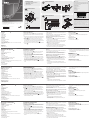
Front View
1. Handle
2. Slide Release
3. LCD Display
4. LCD Controls
5. Keyboard
6. Touchpad
7. CPU LED
*
8. Rack Mounting Brackets
9. Lock LEDs
10. LCD On / Off Button
11. LED Illumination Light
* For CL1000N, lights to indicate that the unit is connected to the KVM
(CPU) port
Rear View
1. Power Socket
2. KVM(CPU) Port
Description de l’appareil
A
Vue avant
1. Poignée
2. Bouton coulissant d'ouverture
3. Écran LCD
4. Commandes LCD
5. Clavier
6. Pavé tactile
7. Voyant du port CPU*
8. Supports de xation pour montage sur bâti
9. Voyants de verrouillage
10. Bouton marche/arrêt de l’écran LCD
11. Eclairage LED
* Pour la console CL1000N, ce voyant s’allume a n d’indiquer que l’unité
est connectée au port KVM (CPU)
Vue arrière
1. Prise d'alimentation
2. Port KVM (CPU)
Hardwareübersicht
A
Vorderseitige Ansicht
1. Griff
2. Ausziehentriegelung
3. LCDDisplay
4. LCDBedienelemente
5. Tastatur
6. Touchpad
7. CPU-LED-Anzeige*
8. Schienen für die Rackmontage
9. Verriegelungs-LEDs
10. Ein-/Ausschalter für LCD-Schirm
11. LED-Beleuchtung
* Leuchtet beim CL1000N auf, wenn das Gerät mit dem KVM- bzw.
CPU-Port verbunden ist.
Rückseitige Ansicht
1. Netzeingangsbuchse
2. KVM-Port (CPU-Port)
Hardware Installation
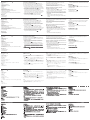
Standard Rack Mounting
B
A standard rack mount kit is provided with your CL1000N. The kit
enables the console to be mounted in rack with a depth of 52–85
cm.
1. While one person positions the CL1000N in the rack and holds it
in place, the second person loosely screws the front brackets to
the rack.
B-1
2. While the rst person still holds the CL1000N in place, the
second person slides the L brackets into the CL1000N's side
mounting brackets from the rear until the bracket anges contact
the rack, then screws the L brackets to the rack.
B-2
3. After the L brackets have been secured, tighten the front bracket
screws.
B-3
Installation du matériel
Montage sur rack standard
B
Un kit de montage sur rack standard est fourni avec le CL1000N.
Ce kit permet de monter le commutateur sur rack, avec une
profondeur de 52 à 85 cm.
B-1
1. Pendant qu'une première personne positionne le commutateur
dans le rack et le maintient en place, une deuxième visse les
supports avant sur le bâti.
B-2
2 Pendant que la première personne maintient toujours en place
le commutateur, la deuxième fait glisser les supports en L dans
les supports de montage latéraux du commutateur, à l'arrière,
jusqu'à ce que les brides des supports entrent en contact avec le
bâti, puis visse les supports en L sur le bâti.
B-3
3. Une fois les supports en L sécurisés, serrez les vis des supports
avant.
Hardware installieren:
StandardRackMontage
B
Mit dem CL1000N wird ein Montagekit für ein StandardRack
mitgeliefert. Mit diesem Kit können Sie den Switch in ein Rack mit
einer Tiefe von 52-85 cm einbauen.
B-1
1. Während die eine Person den Switch in den Rack schiebt und
festhält, setzt die zweite Person die Schrauben lose auf die
Montageschienen.
B-2
2. Während die erste Person den Switch nach wie vor festhält,
schiebt die zweite die L-Schienen von hinten auf die seitlichen
Montagerahmen des Switches, bis der Flansch den Rack berührt.
Schrauben Sie die L-Schienen anschließend am Rack fest.
B-3
3. Nachdem Sie die L-Schienen befestigt haben, ziehen Sie auch
die Schrauben an der Vorderseite fest.
Note:
• It takes two people to mount the unit: one to hold it in place; the
other to screw it in.
• Optional mounting kits – including single person Easy Installation
kits – are available with a separate purchase.
Refer to the installation diagram as you perform the
installation steps:
C
1. Plug the SPHD connector end of the KVM cable provided with
this unit into the CL1000N's KVM port.
2. Plug the keyboard, monitor, and mouse connectors of the KVM
cable provided with this unit into the 5 in 1 console cable that
connected to the section of the KVM switch.
Note:
• Supports PS/2 or USB KVM switches
• Supports computers with PS/2 or USB keyboard and mice
3. Plug the power cord into the CL1000N's power socket and into
an AC power source to power up your KVM installation.
Remarque :
• Deux personnes sont nécessaires pour monter l’unité : une pour
la tenir en place et l'autre pour la visser.
• Des kits de montage en option, y compris des kits faciles à
installer par une seule personne, sont disponibles séparément.
Reportez-vous au schéma d'installation pendant les
différentes étapes de l’installation :
C
1. Branchez le connecteur SPHD à 15 broches du câble KVM
fourni avec cette unité sur le port KVM du CL1000N.
2. Branchez les connecteurs du clavier, du moniteur et de la souris
du câble KVM fourni sur le câble de console 5 en 1 qui est
connecté à la section correspondante du commutateur KVM.
Remarque :
• Prend en charge les commutateurs KVM PS/2 ou USB
• Prend en charge les ordinateurs équipés de claviers et souris
PS/2 ou USB
Hinweis:
• Zur Montage sind zwei Personen erforderlich: eine zum Festhalten
und die andere zum Verschrauben der Einheit.
• Optionale Montagekits – darunter auch solche, die durch eine
Einzelperson installiert werden können – sind optional erhältlich.
Für die Durchführung der folgenden Schritte, siehe das
Installationsdiagramm:
C
1. Verbinden Sie den 15poligen SPHDAnschluss des mitgelieferten
KVMKabels mit dem KVMPort am CL1000N.
2. Verbinden Sie die Tastatur-, Monitor- und Mausanschlüsse des
mitgelieferten KVM-Kabels mit den betreffenden Ports des 5-in-
1-Konsolkabels, das an den entsprechenden Abschnitt des KVM-
Switches angeschlossen ist.
Hinweis:
• Unterstützt PS/2- oder USB-KVM-Switches
• Unterstützt Computer mit PS/2- oder USB-Tastatur und -Maus
Operation
D
Opening the console
D-1
1. Push the catches inward.
2. Slide the module all the way out until it automatically locks in
place.
3. Open the cover
Closing the console
D-2
1. Close the cover
2. Push the module all the way in
3. Branchez le cordon d’alimentation dans la prise d’alimentation de
la CL1000N et dans une source d’alimentation CA pour alimenter
votre installation KVM.
Opération
D
Ouverture de la console
D-1
1. Poussez les loquets vers l’intérieur.
2. Faites coulisser le module à fond vers l’extérieur jusqu’à ce qu’il
se verrouille en place.
3. Ouvrez le couvercle
Fermeture de la console
D-2
1. Fermez le couvercle
2. Poussez le module à fond vers l’intérieur
3. Verbinden Sie das Netzkabel mit der Stromeingangsbuchse
des CL1000N und dem Stromnetz, um Ihre KVM-Installation mit
Strom zu versorgen.
Betrieb
D
Konsole öffnen
D-1
1. Schieben Sie die Riegel zusammen.
2. Ziehen Sie das Modul ganz heraus, bis es eigenständig einrastet.
3. Klappen Sie es auf.
Konsole schließen
D-2
1. Klappen Sie das Modul zu.
2. Schieben Sie das Modul ganz hinein.
B
C D
Package Contents
1 CL1000N with Standard Mounting Kit
1 Custom KVM Cable Set
1 Power Cord
1 User Instructions
Hardware Installation
Hardware Installation Operation
© Copyright 2015 ATEN
®
International Co., Ltd.
ATEN and the ATEN logo are trademarks of ATEN International Co., Ltd. All rights reserved. All
other trademarks are the property of their respective owners.
This product is RoHS compliant.
Part No. PAPE-1223-A11G Printing Date: 01/2015
19" LCD Console
Quick Start Guide
CL1000N
CL1000N 19" LCD Console Quick Start Guide
www.aten.com
Console LCD 19’’ CL1000N – Guide de démarrage rapide
www.aten.com
CL1000N 19-Zoll-LCD-Konsole Kurzanleitung
www.aten.com
CL1000N Consola con pantalla LCD de 19 pulgadas Guía rápida
www.aten.com
Console CL1000N con schermo LCD da 19 pollici – Guida rapida
www.aten.com
D-1
D-2
L Brackets
Side Mountng
Brackets
B-1
B-2
B-3
Front View
Rear View
9
11
10
8
3
4
5
6
7
2
1
2
EXIT I LIGHT
Press the Exit/Light
pushbutton for two seconds
to turn the LED light
ON or Off. (Default: On)
1 2
1
3
2
3
CS1716A
USB
PS/2
Presentación del hardware
A
Vista frontal
1. Asa
2. Desbloqueo retráctil
3. Pantalla LCD
4. Controles LCD
5. Teclado
6. Panel táctil
7. Indicador LED de CPU*
8. Escuadras para montaje en rack
9. Indicadores LED de bloqueo
10. Botón encender/apagar LCD
11. Iluminacion LED
* Se ilumina para indicar que el CL1000N está conectado al puerto
KVM (CPU).
Vista posterior
1. Entrada de alimentación
2. Puerto KVM (CPU)
Instalación del hardware:
Montaje en rack estándar
B
Con el CL1000N viene un kit de montaje en rack estándar. Con
este kit puede montarlo en un rack con una profundidad entre 52 y
85 cm.
B-1
1. Mientras una persona coloca el conmutador en el rack y lo
aguanta en su sitio, una segunda atornilla (sin apretar) la parte
frontal de los raíles en el rack.
B-2
2. Mientras la primera persona sigue aguantando el conmutador,
la segunda desliza los raíles en L sobre el conmutador desde la
parte trasera hasta que la pestaña del soporte haga contacto con
el rack y luego atornilla los raíles en L al rack.
B-3
3.
Cuando tenga los raíles en L atornillados, apriete también los
tornillos frontales de los raíles.
Nota:
• Hacen falta dos personas para instalar la unidad: una que la
coloca en su sitio y la otra que la atornilla.
• Existen kits de montaje opcionales – incluyendo kits de montaje
para una sola persona.
Véase el diagrama de instalación cuando vaya a efectuar
los pasos listados a continuación:
C
1. Enchufe el conector SPHD de 15 patillas del cable KVM incluido
al puerto KVM del CL1000N.
2. Enchufe los conectores para teclado, monitor y mouse del cable
KVM incluido al cable 5 en 1 de consola que está conectado a la
sección correspondiente del conmutador KVM.
Nota:
• Admite conmutadores KVM de tipo PS/2 o USB
• Admite computadoras con con guraciones de teclado y de
mouse PS/2 o USB
3. Enchufe el cable de alimentación a la entrada de alimentación
del CL1000N y a una toma eléctrica para encender su instalación
de KVM.
Funcionamiento
D
Abrir la consola
D-1
1. Empuje los pestillos hacia dentro.
2. Saque el módulo del todo hasta que quede encajado
automáticamente.
3. Abra el panel.
Cerrar la consola
D-2
1. Cierre el panel.
2. Empuje el modulo completamente hacia dentro.
Panoramica sull’hardware
A
Vista anteriore
1. Maniglia
2. Sganciamento della slitta retraibile:
3. Display a cristalli liquidi
4. Comandi LCD
5. Tastiera
6. Touchpad
7. LED della CPU*
8. Staffe per il montaggio in rack
9. LED di blocco
10. Pulsante di accensione/spegnimento dello schermo
11. Illuminazione LED
* Per la CL1000N, si illumina per indicare che l’unità è connessa alla
porta KVM (CPU)
Vista posteriore
1. Presa per l’alimentazione
2. Porta KVM (CPU)
Installazione dell’hardware:
Montaggio in rack standard
B
Un kit standard di montaggio su rack ne fornito insieme all'unità
CL1000N. Il kit consente il montaggio dello switch su rack con una
profondità di 52-85 cm.
B-1
1. Mentre una persona posiziona lo switch nel rack e lo mette in
posizione, la seconda persona ssa provvisoriamente i supporti
frontali al rack.
B-2
2. Mentre la prima persona continua a tenere in posizione lo
switch, la seconda fa scivolare i supporti a L nei supporti laterali
di montaggio dello switch, partendo dal retro, no a quando
non sono a stretto contatto con il rack e poi, utilizzando le viti in
dotazione al kit, avvita i supporti a L al rack.
B-3
3. Una volta ssati i supporti a L, stringere le viti dei supporti
anteriori.
Nota:
• Per montare l’unità sono necessarie due persone: una per tenerla
ferma in posizione, l’altra per avvitarla.
• I kit di montaggio opzionali – compresi i kit d’installazione facile
per una sola persona – sono disponibili in vendita separatamente.
Nell’eseguire i punti successivi fare riferimento al
diagramma d’installazione:
C
1. Inserire l’estremità del connettore SPHD a 15 pin del cavo KVM
fornito con il dispositivo nella porta KVM del CL1000N.
2. Inserire i connettori della tastiera, del monitor e del mouse del
cavo KVM fornito con l’unità nel cavo console 5 in 1 collegato alla
sezione dello switch KVM.
Nota:
• Supporta switch KVM PS/2 o USB
• Supporta computer con tastiere e mouse PS/2 o USB
3. Inserire la spina del cavo dell’alimentazione nella presa
dell’alimentazione della CL1000N e in una presa d’alimentazione
CA per alimentare l’installazione KVM.
Funzionamento
D
Funzionamento della console:
D-1
1. Spingere verso l’interno le chiusure.
2. Far scivolare completamente fuori il modulo no a quando non si
ssa in posizione.
3. Aprire il coperchio
Chiusura della console:
D-2
1. Chiudere il coperchio
2. Far rientrare completamente il modulo
Important Notice
Considering environmental protection, ATEN does not provide a fully
printed user manual for this product. If the information contained in
the Quick Start Guide is not enough for you to confi gure and operate
your product, please visit our website www.aten.com, and
download the full user manual.
Online Registration
http://eservice.aten.com
Technical Phone Support
International:
886-2-86926959
North America:
1-888-999-ATEN Ext: 4988
United Kingdom:
44-8-4481-58923
All information, documentation, firmware, software utilities, and
specifi cations contained in this package are subject to change without
prior notification by the manufacturer. Please visit our website http://
www.aten.com/download/?cid=dds for the most up-to-date versions.
EMC Information
FEDERAL COMMUNICATIONS COMMISSION INTERFERENCE STATEMENT:
This equipment has been tested and found to comply with the limits for a Class A
digital device, pursuant to Part 15 of the FCC Rules. These limits are designed to provide
reasonable protection against harmful interference when the equipment is operated
in a commercial environment. This equipment generates, uses, and can radiate radio
frequency energy and, if not installed and used in accordance with the instruction
manual, may cause harmful interference to radio communications. Operation of this
equipment in a residential area is likely to cause harmful interference in which case the
user will be required to correct the interference at his own expense.
FCC Caution: Any changes or modifi cations not expressly approved by the party
responsible for compliance could void the user's authority to operate this equipment.
CE Warning: This is a class A product. In a domestic environment this product may cause
radio interference in which case the user may be required to take adequate measures.
The following contains information that relates to China:
A
Hardware Review
La pagina si sta caricando...
-
 1
1
-
 2
2


ATEN 19" PS/2 VGA LCD Console Guida Rapida
- Categoria
- Switch KVM
- Tipo
- Guida Rapida
in altre lingue
- English: ATEN 19" PS/2 VGA LCD Console Quick start guide
- français: ATEN 19" PS/2 VGA LCD Console Guide de démarrage rapide
- español: ATEN 19" PS/2 VGA LCD Console Guía de inicio rápido
- Deutsch: ATEN 19" PS/2 VGA LCD Console Schnellstartanleitung
- русский: ATEN 19" PS/2 VGA LCD Console Инструкция по началу работы
- português: ATEN 19" PS/2 VGA LCD Console Guia rápido
- 日本語: ATEN 19" PS/2 VGA LCD Console クイックスタートガイド
Documenti correlati
-
ATEN CL1000 Guida Rapida
-
-
-
-
-
ATEN KL1508AiM Guida Rapida
-
-
ATEN CL3100 Guida Rapida
-
-