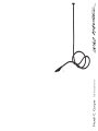
Ingo Maurer Metall C. Cooper Istruzioni per l'uso
- Tipo
- Istruzioni per l'uso

Metall C. Cooper Instructions

Deutsch Seite 4
English Page 7
Français Page 10
Italiano Pagina 13
Zeichnungen Seite 16
Drawings Page 16
Dessins Page 16
Disegni Pagina 16
3
Montageanleitung
Bitte vor der Montage aufmerksam lesen und aufbe-
wahren!
Instructions for assembly
Please read these instructions carefully before going
any further, and keep them in a safe place for future
reference!
Instructions de montage
A lire attentivement avant le montage et à conserver
soigneusement!
Istruzioni di montaggio
Prima del montaggio leggere attentamente le pre-
senti istruzioni e conservarle!
2

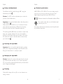
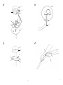
Einrichten
Der Reflektor lässt sich am Haltestab (9) 360° um die
eigene Achse drehen. 3
Achtung: Bitte benutzen Sie den Haltestab NICHT zum
Verstellen des flexiblen Schlauches.
Wichtig: Verstellen Sie die Position des Reflektors immer
am flexiblen Schlauch. 4
Positionieren Sie den Reflektor immer so, dass der Mindest-
abstand von 30 cm zur Leuchte, zum Kabel und zu anderen
brennbaren Teilen eingehalten wird.
Mit Hilfe des beiliegenden Sicherungsseils (10) lassen sich
größere Spannweiten der Lampe verwirklichen. Das eine
Ende des Seils muss kurz hinter dem Lampenkopf am
Schlauch befestigt werden; das andere Ende wird so an
der Leuchte befestigt, dass das Seil unter Zug steht. Das
Sicherungsseil verhindert, dass sich der Reflektor von
allein senkt. 5
Einsetzen des Leuchtmittels
Wichtig: Berühren Sie das Leuchtmittel nicht mit bloßen
Händen (Einbrenngefahr). Setzen Sie das Leuchtmittel in
die Fassung ein und achten Sie auf richtigen Sitz.
Wechsel des Leuchtmittels
Achtung: Schalten Sie die Sicherung des Deckenauslasses
aus und lassen Sie die Lampe vollständig abkühlen.
Berühren Sie das neue Leuchtmittel nicht mit bloßen
Händen (Einbrenngefahr).
Montage und Elektroanschluss sind von einer Elektrofach-
kraft auszuführen.
Achtung: Schalten Sie die Sicherung des Deckenauslasses
vor der Montage aus. Achten Sie unbedingt auf den Verlauf
der Elektroleitung, damit auf keinen Fall das Kabel ange-
bohrt wird.
Beigepackt sind
2 Schrauben und Dübel S6
1 Baldachin und 2 Befestigungsschrauben
1 Leuchtmittel
1 Sicherungsseil
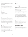
Montagevorbereitung
Benutzen Sie den Baldachin (1) als Schablone zum Markie-
ren der Bohrlöcher. Bohren Sie zwei Dübellöcher Ø 6 mm,
setzen Sie die Dübel S6 ein und schrauben Sie den Bal-
dachin mit beiliegenden Schrauben (2) fest. Lassen Sie die
Zuleitung (3) etwa 5 cm aus der Dose ragen und isolie-
ren Sie die Enden von Leiter, Neutral- und Schutzleiter
jeweils ca. 5 mm ab. 1
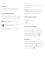
Montage
Schließen Sie Leiter und Neutralleiter des Deckenauslasses
in der Lüsterklemme (4) an. Schließen Sie den Schutzleiter
an der markierten Erdungsklemme (5) an. Schrauben Sie
die Montageplatte (6) mit den beiden vormontierten
Schrauben am Baldachin fest. 1
Die Baldachinabdeckung (7) wird mit Hilfe der Magneten (8)
an der Montageplatte befestigt. 2
5
4
DeutschDeutsch

English
The lamp assembly and all electrical work must be carried
out by a qualified electrician.
Caution: Switch off or remove the fuse for the ceiling
outlet before beginning the assembly. Take care to ascer-
tain the exact position of all electrical wiring, so as to
avoid accidentally drilling into a power cable.
Enclosed:
2 screws and plugs S6
I canopy with 2 pre-assembled screws
1 light bulb
1 retaining cable
Preparations for assembly
Use the canopy (1) as a template to mark the drill holes.
Drill the two 6 mm-diameter holes, insert the S6 plugs
and attach the canopy to the ceiling with the screws (2)
provided. Pull the mains cable (3) about 5 cm out of the
ceiling outlet and strip about 5 mm of the insulation from
the ends of the phase, neutral and earth wires. 1
Assembly
Connect the phase and neutral wires from the ceiling out-
let to the contacts in the lamp terminal (4). Connect the
earth wire to the marked earth clamp (5). Attach the
mounting plate (6) to the canopy with the two pre-
assembled screws. 1
The canopy cover (7) is fastened to the mounting plate
with the magnets (8). 2
6
Pflege
Bitte verwenden Sie zur Reinigung nur ein feuchtes Tuch,
jedoch keine lösungsmittelhaltigen Reinigungsmittel.
Technische Daten
230 V~50 Hz; 125 V~60 Hz. Die für Ihre Leuchte zutreffende
Spannung und Frequenz entnehmen Sie bitte dem Typenschild.
Leuchtmittel: Hochvolt Halogen, max. 60 Watt, Sockel G9.
Mindestabstand zu brennbaren Flächen: 30 cm
Dieses Symbol weist darauf hin, dass zwingend
ein “self-shielded”-Leuchtmittel verwendet wer-
den muss.
Eventuell notwendige Reparaturen dürfen nur von einer
Elektrofachkraft durchgeführt werden.
Deutsch
7

Technical specification
230 V~50 Hz; 125 V~60 Hz. The correct voltage and fre-
quency for your lamp are indicated on the type label.
High-voltage halogen bulb, max. 60 W, G9 base.
Minimum distance from flammable surfaces: 30 cm
This symbol means that only self-shielded light
bulbs may be used.
Any repairs that become necessary must be performed
by a qualified electrician.
English
English
Set-up and adjustment
The reflector can be rotated through 360°, using the
adjustment pin (9). 3
Caution: Do NOT use the adjustment pin to alter the
position of the flexible tube.
Important: Use only the flexible tube to alter the position
of the reflector. 4
Always position the reflector so as to observe the mini-
mum clearance requirement of 30 cm from the lamp
body, the power lead and all flammable materials.
The retaining cable (10) makes it possible to suspend the
lamp over a greater distance. One end of the cable is
attached to the flexible tube near the head of the lamp;
the other end is fixed so that the cable is taut and sup-
ports the head. 5
Inserting the light bulb
Important: Do not touch the light bulb with your bare
hands (risk of fingermark damage). Insert the bulb in the
fitting and ensure that it is securely in place.
Changing the light bulb
Caution: Switch off or remove the mains fuse for the ceil-
ing outlet and allow the lamp to cool down completely.
Do not touch the replacement bulb with your bare hands
(risk of fingermark damage)!
Cleaning
Clean with a damp cloth only. Do not use cleaners con-
taining solvents.
9
8

Orientation
Le réflecteur tourne à 360° sur lui-même à l’aide de la
tige de fixation (9). 3
Attention: N’utilisez PAS la tige de fixation pour régler le
tuyau flexible.
Important: Réglez toujours la position du réflecteur à
l’aide du tuyau flexible. 4
Positionnez toujours le réflecteur de manière à ce qu’une
distance minimale de 30 cm soit respectée par rapport à
l’ampoule, au câble et à d’autres pièces inflammables.
Le câble d’arrêt (10) permet de régler l’ouverture de la
lampe. Une extrémité du câble doit être fixée juste der-
rière la tête de la lampe au niveau du tuyau, l’autre est
fixée à l’ampoule de manière à ce que le câble soit tendu.
Le câble d’arrêt peut empêcher que le réflecteur ne s’a-
baisse seul. 5
Insertion de l’ampoule
Important: Ne touchez pas l’ampoule à mains nues (ris-
que de brûlure). Insérez l’ampoule dans le logement et
veillez à ce qu’elle soit bien fixée.
Remplacement de l’ampoule
Attention: Débranchez le fusible contrôlant l’arrivée de
courant au plafond et laissez complètement refroidir l’am-
poule. Ne touchez pas la nouvelle ampoule à mains nues
(risque de brûlure).
Français
Français
Le montage et le branchement électrique sont à effectuer
par un électricien.
Attention: Débranchez le fusible de sécurité de la boîte
de sortie du courant au niveau du plafond avant de pro-
céder au montage. Apportez une attention particulière au
tracé des conduites d'électricité afin de ne pas percer un
câble.
Fournitures:
2 vis et chevilles S6
1 baldaquin et 2 vis de fixation
1 ampoule
1 câble d’arrêt
Préparation du montage
Utilisez le baldaquin (1) comme patron pour marquer les
trous à percer. Percez deux trous pour les chevilles Ø 6 mm,
insérez les chevilles S6 et fixez le baldaquin à l’aide des vis
fournies (2). Laissez dépasser le câble d’alimentation élec-
trique (3) de 5 cm de la boîte et dénudez les extrémités
du câble conducteur, du conducteur neutre et du conduc-
teur de protection sur 5 mm. 1
Montage
Raccordez le câble conducteur et le conducteur neutre
de la sortie électrique du plafond au serre-fils (4).
Raccordez le conducteur de protection à la borne de
terre marquée (5). Vissez la plaque de montage à l'aide
des deux vis pré-montées au baldaquin. 1
Le cache du baldaquin sera fixé à la plaque de montage à
l'aide d'aimants. 2
10 11

Il montaggio e collegamento alla rete devono essere eseguiti
da un elettricista.
Attenzione: Prima del montaggio staccare la corrente
dell’uscita della corrente a soffitto. Fare assolutamente
attenzione al percorso delle linee di alimentazione per
evitare di danneggiare un cavo durante la foratura.
Nella fornitura sono inclusi:
2 viti e tasselli S6
1 rosone e 2 viti di fissaggio
1 lampadina
1 cavetto di sicurezza
Preparazione del montaggio
Usare il rosone (1) come dima di foratura per contrasse-
gnare i punti da forare. Effettuare i due fori per i tasselli
di Ø 6 mm., inserire i tasselli S6 e fissare il rosone con le
viti (2) incluse. Lasciare spuntare i fili di alimentazione (3)
di circa 5 cm. dalla scatola e spelare le estremità di fase,
neutro e terra rispettivamente di circa 5 mm. 1
Montaggio
Collegare fase e neutro dell’uscita della corrente a soffitto
al morsetto (4). Collegare la terra al morsetto di terra
contrassegnato (5). Con le due viti premontate avvitare
la piastra di montaggio (6) al rosone. 1
La coper tura (7) del rosone viene fissata alla piastra di
montaggio con i magneti (8). 2
Italiano
Entretien
Veuillez uniquement utiliser un chiffon humide pour le
nettoyage et pas de produits contenant des solvants.
Caractéristiques techniques
230 V~50 Hz; 125 V~60 Hz. Vous trouverez la tension et la
fréquence adaptées à votre lampe sur la plaque signalétique.
Ampoule: Halogène haut voltage, max. 60 watts, culot G9.
Distance minimale par rapport aux surfaces
inflammables: 30 cm
Ce symbole indique l’utilisation obligatoire d’une
ampoule «auto-protégée».
Les réparations nécessaires peuvent uniquement être
réalisées par un électricien.
Français
13
12

Cura
Per la pulizia della lampada usare soltanto un panno
umido e mai prodotti contenenti solventi.
Dati tecnici
230 V~50 Hz; 125 V~60 Hz. I dati tecnici relativi alla ten-
sione e alla frequenza di funzionamento della Vostra lampa-
da sono riportati sulla targhetta d’identificazione.
Lampadina: alogena ad alto voltaggio, max. 60 W, attacco G9.
Distanza minima da superfici infiammmabili: 30 cm.
Questo simbolo indica che è consentito esclusiva-
mente l’impiego di lampadine di tipo autoprotetto.
Eventuali riparazioni devono essere eseguite esclusivamente
da un elettricista.
Italiano
Regolazione
Il riflettore può essere ruotato di 360° sul proprio asse
mediante l’astina di regolazione (9). 3
Attenzione: NON usare l’astina di regolazione per rego-
lare la guaina flessibile della lampada.
Importante: Regolare la posizione del riflettore sempre
mediante la guaina flessibile. 4
Posizionare sempre il riflettore in modo da lasciare una
distanza di almeno 30 cm. dalla lampada, dal cavo e da
qualsiasi altro oggetto infiammabile.
Mediante il cavetto di sicurezza (10) incluso è possibile
ottenere estensioni maggiori della lampada. Fissare un’estre-
mità del cavetto alla guaina flessibile direttamente dietro il
riflettore della lampada; successivamente sistemare l’altra
estremità alla lampada in modo che il cavetto sia in tensione.
Il cavo di sicurezza impedisce che il riflettore si abbassi
involontariamente. 5
Inserimento della lampadina
Importante: Non toccare la nuova lampadina a mani
nude (pericolo di impressione a caldo di residui grassi o
polverosi). Inserire la lampadina nel portalampada e assi-
curarsi che sia correttamente inserita.
Sostituzione della lampadina
Attenzione: Staccare la corrente dell’uscita della corrente
a soffitto e attendere che la lampada sia completamente
fredda. Non toccare la nuova lampadina a mani nude (peri-
colo di impressione a caldo di residui grassi o polverosi).
Italiano
15
14

17
16
3
4
2
1
360°
9
1
2
2
3
4
5
6
7
8
7
8
6
1

Ingo Maurer GmbH
Kaiserstrasse 47
80801 München
Germany
T. +49. 89. 381606-0
F. +49. 89. 381606 20
info@ingo-maurer.com
www.ingo-maurer.com
Oktober 2009 Made in Germany
F
Made in Germany
F
Made in Germany
F
Made in Germany
5
18
10
-
 1
1
-
 2
2
-
 3
3
-
 4
4
-
 5
5
-
 6
6
-
 7
7
-
 8
8
-
 9
9
-
 10
10


Ingo Maurer Metall C. Cooper Istruzioni per l'uso
- Tipo
- Istruzioni per l'uso
in altre lingue
Documenti correlati
-
Ingo Maurer Alizz T. Cooper Istruzioni per l'uso
-
-
-
-
-
-
-
-
-