
Operator‘s manual
Translation of the original Operating Manual
Nr.
Rotary Harrow
LION 253 classic
(Type 8760: + . . 00135)
LION 303 classic
(Type 8761: + . . 00192)
LION 303.12 classic
(Type 8762: + . . 00118)
LION 303 WG
(Type 8771: + . . 00635)
LION 303.12 WG
(Type 8772: + . . 00324)
LION 353.14 WG
(Type 8773: + . . 00045)
LION 403 WG
(Type 8774: + . . 00036)
99+8773.EN.80T.1

1500_GB-PAGE 2
Product liability, information obligation
Product liability obliges manufacturers and dealers to issue operating instructions for the machine at the point of sale and to instruct
the customer on the operation, safety and maintenance regulations governing the machine.
A confirmation is required to verify that the machine and operating instructions have been handed over correctly.
For this purpose
- Document A is to be signed and returned to Pöttinger or via the internet to www.poettinger.at
- Document B remains with the specialist dealer handing over the machine.
- The customer receives document C.
For the purposes of product liability law, every farmer is an entrepreneur.
In the terms of product liability law, damage to property is any damage arising due to the machine, but not to the machine, and an
excess (500 euros) exists for this liability.
Corporate damage to property within the terms of the product liability law is excluded from this liability.
Be advised! The operating instructions must also be handed over with any subsequent machine sale or transfer and the transferee
must be instructed in the regulations stated.
Pöttinger - Trust creates Affi nity - since 1871
"Quality pays for itself." Therefore we apply the highest quality standards to our products which are constantly monitored by our
in-house quality management and our management board. Because the safety, perfect function, highest quality and absolute
reliability of our machines in operation are the core competencies for which we stand.
There may be deviations between these instructions and the product as we are constantly developing our products. Therefore no
claims may be derived from the data, illustrations and descriptions. Please contact your Specialist Service Centre for any binding
information about specific features of your machine.
We would ask you to please understand that changes to the scope of supply with regard to form, equipment and technical
specifications are possible at any time.
Any form of reprint, translation or reproduction, including excerpts, requires the written approval of Pöttinger Landtechnik GmbH.
All rights according to copyright laws remain expressly reserved by Pöttinger Landtechnik GmbH.
© Pöttinger Landtechnik GmbH – 31st October 2012
Refer to PÖTPRO for additional information about your machine:
Are you looking for suitable accessories for your machine? No problem! All the information you require is here at your disposal.
Scan the QR code on the machine's type plate or look under www.poettinger.at/poetpro
And if we don't have what your looking for, then your Specialist Service Centre is there for you with help and advice.

Dokument D
GB-0600 Dokum D Anbaugeräte - 3 -
PÖTTINGER Landtechnik GmbH
Industriegelände 1
A-4710 Grieskirchen
Tel. 07248 / 600 -0
Telefax 07248 / 600-2511
❑ Machine checked according to delivery note. All attached parts removed. All safety equipment, drive shaft and operating
devices at hand.
❑ Operation and maintenance of machine and/or implement according to operating instructions explained to the customer.
❑ Tyres checked re. correct pressure.
❑ Wheel nuts checked re. tightness.
❑ Drive shaft cut to correct lenght.
❑ Correct power-take-off speed indicated.
❑ Fitting to tractor carried out: to three-point linkage
❑ Trial run carried out and no defects found.
❑ Functions explained during trial run.
❑ Pivoting in transporting and operating position explained.
❑ Information given re. optional extras.
❑ Absolute need to read the operating manual indicated.
Please check. X
According to the product liability please check the above mentioned items.
INSTRUCTIONS FOR
PRO DUCT DELIVERY
EN
In order to prove that the machine and the operating manual have been properly delivered, a confirmation is necessary.
For this purpose please do the following:
- sign the document A and send it to the company Pöttinger or via the internet to www.poettinger.at
- document B stays with the specialist factory delivering the machine.
- document C stays with the customer.

- 4 -
EN
INTRODUCTION
1700_GB-Introduction
Introduction
Dear Customer
These Operating Instructions are intended to allow you
to familiarise yourself with the implement and provide
you with clear information on safe and correct handling,
care and maintenance. Thus please take the time to read
these Instructions.
These Operating Instructions comprise part of the imple-
ment. They are to be kept at a suitable location and acces-
sible to staff over the entire service life of the implement.
Instructions based on the national provisions regarding
protection against accidents, road traffic and environmental
protection are also to be applied additionally.
Any persons commissioned with the operation, maintenance
or transport of the implement must read and understand
these Instructions, in particular the safety information, prior
to starting work. Any warranty claims lapse on non-obser-
vance of these Instructions.
In case you have questions related to this operation manual
or further questions about this implement, please contact
your dealer.
Care and maintenance performed in good time and scru-
pulously according to the maintenance intervals specified
ensure operational and traffic safety as well as the reliability
of the implement.
Use only the original spare parts and accessories from
Pöttinger or accepted by Pöttinger. For those parts relia-
bility, safety and suitability for Pöttinger machines can be
assured. Warranty claims lapse if non-approved parts are
used. The use of original parts is also recommended after
the warranty period has expired to maintain the performance
of the implement in the long term.
Product liability legislation obliges the manufacturer and
the authorised dealer to issue Instructions when selling
implements and to instruct customers in the use with refer-
ence to the safety, operating and maintenance regulations.
Confirmation in the form of a declaration of transfer is
required to verify that the implement and Instructions have
been transferred correctly. The declaration of transfer was
attached to the implement on delivery.
Every self-employed person and farmer is an entrepreneur
within the meaning of the product liability legislation. In
accordance with the laws of product liability, entrepre-
neurial property damages are excluded from the liability.
All damage to property within the meaning of the product
liability legislation is regarded as damage caused by the
implement but not to the implement.
These Operating Instructions are integral part of the imple-
ment delivery scope. You should therefore hand them over to
the new owner if ownership of the implement is transferred.
Train and instruct the new owner in the regulations stated.
The Pöttinger Service-Team wishes you good luck.

- 5 -
1901_EN-Inhalt_8773
CONTENTS EN
Table of contents
Introduction ................................................................ 4
SYMBOLS USED
CE mark ..................................................................... 6
Safety hints: ............................................................... 6
Position of the warning signs ..................................... 7
TRACTOR REQUIREMENTS
Tractor ........................................................................ 9
Ballast weights ........................................................... 9
Lifting unit (three-point linkage) ................................. 9
Necessary hydraulic connections .............................. 9
Necessary power connections ................................... 9
HITCHING THE IMPLEMENT
Loading information ................................................. 10
Preparing for hitching to the tractor .......................... 10
Safety advice ............................................................11
Hitching the implement .............................................11
Unhitching implement .............................................. 12
TRANSPORT
Safety advice ........................................................... 13
transport position ..................................................... 13
Rotor Speed ............................................................. 15
Working depth .......................................................... 16
Scraper plate of the rollers ....................................... 16
Side boards ...............................................................17
Levelling bars ........................................................... 18
Hydraulic upper link (optional equipment) ............... 19
OPERATION
Operation ................................................................. 20
ROW MARKERS
Row markers (optional equipment) ......................... 21
Install mounted seed drill - Hydrolift ......................... 22
VITASEM 252/302/402 classic................................. 22
Remove mounted seed drill - Hydrolift ..................... 23
Attach mountable seed drill machine - mechanical
upper link ................................................................. 23
VITASEM A / ADD, AEROSEM A /ADD .................. 23
Detach mountable seed drill - mechanical
upper link ................................................................. 25
Attach seed drill - hydraulic upper link ..................... 25
VITASEM A / ADD ................................................... 25
Detach mountable seed drill - hydraulic upper link .. 27
Guide values for the length of the upper link ........... 28
MAINTENANCE AND REPAIR
Advice for general maintenance .............................. 29
Tine change ............................................................. 29
Variant: Rapid tine replacement ............................... 29
PTO shaft guarding .................................................. 29
Cleaning of machine parts ....................................... 30
Cylindrical - angular gears ....................................... 30
Classic - Angular gear ............................................. 30
Bar lubrication .......................................................... 30
Winter storage.......................................................... 30
Disposal of old equipment ....................................... 30
Lubrication chart ...................................................... 31
LION 103 .................................................................. 32
Observe Safety
Points in Supple-
ment A!
TECHNICAL DATA
Technical data .......................................................... 33
Position of type plate................................................ 34
Variations of type plates ........................................... 34
Designated use of the rotary harrow ........................ 34
SUPPLEMENT
SAFETY ADVICE
Lubricants ................................................................ 39
Combination of tractor and mounted implement ...... 44

- 6 -
1801_EN-Sicherheit ANSI
EN
SYMBOLS USED
CE mark
The CE mark, which is affixed by the manufacturer, indicates outwardly that this machine conforms to the engineering
guideline regulations and the other relevant EU guidelines.
EU Declaration of Conformity (see Attachment)
By signing the EU Declaration of Conformity, the manufacturer declares that the machine that
is brought into service complies with all relevant fundamental safety and health requirements.
Safety hints:
These Operating Instructions contain the
following Figures:
DANGER
If you do not follow the instructions in a text section
with this marking, there is a risk of fatal or life-
threatening injury.
• All instructions in such text sections must be
followed!
WARNING
If you do not observe the instructions marked this
way, there is the risk of a severe injury.
• All instructions in such text sections must be
followed!
CAUTION
If you do not observe the instructions marked this
way, there is the risk of an injury.
• All instructions in such text sections must be
followed!
NOTE
If you do not observe the instructions marked this
way, there is the risk of material damage.
• All instructions in such text sections must be
followed!
TIP
The text sections marked in this way provide you with
special recommendations and advise regarding the
economical use of the implement.
ENVIRONMENT
The text sections marked in this way provide practices
and advice on environmental protection.
The features marked as (optional) are only available as
standard with specific implement versions or are only
offered for specific versions as optional equipment or are
only offered in certain countries.
Figures may deviate from your implement in detail and are
to be taken as illustrations of operating principle.
Designations such as right and left always apply as the
direction of travel unless the text or illustrations clearly
show otherwise.

- 7 -
1800_AZB_EN_8773
WARNING SIGNS EN
Position of the warning signs
061-17-06
1 Danger - flying objects; keep safe distance from the machine as long
as the engine is running.
bsb 447 410
2 Danger - stay clear of rotating machine parts
3 Never reach into the crushing danger area as long as parts may move.
4 Not step onto the machine when PTO is connected and engine is running.

- 8 -
1800_AZB_EN_8773
WARNING SIGNS EN
5 Before starting up the machine, read the operation instructions.
6 Note on product liability

- 9 -
1800-GB_Tractor requirements_8773
TRACTOR REQUIREMENTS
EN
Tractor
To operate this machine the following tractor requirements
are necessary:
Tractor power:
LION 253 classic
LION 303 classic
LION 303.12 classic
< 140 PS/103 kW
LION 303WG
LION 303.12 WG
< 180 PS/132 kW
LION 353.14WG
LION 403WG
< 200 PS/147 kW
Hitching: Lower linkage Cat. II or Cat. II
Connections: See table
"Necessary hydraulics and
power connections"
Ballast weights
DANGER
Life hazard or material hazard - due to wrong tractor
ballast distribution.
• The front axle of the tractor must always be
loaded with at least 20 % of the unladen
weight of the tractor to guarantee the steer-
ing and braking capacities of the trailer.
20%
Kg
Lifting unit (three-point linkage)
371-08-16
371-08-16
- The tractor’s lifting unit (three-point linkage) must be
designed for the load that occurs. (See technical data)
- The lifting struts are to be set at the same length (4)
using the appropriate adjusting device
(See the tractor manufacturer’s operating manual)
- If the lifting struts at the lower linkages can be locked
in different positions, then the rear position is to be
selected. This relieves the pressure on the tractor’s
hydraulic system.
- The limiting chains and stabilisers of the lower linkage
(5) are to be adjusted so that lateral movement of the
hitched implements is not possible. (Safety measure
for transportation)
Necessary hydraulic connections
Consumer Single-action
hydraulic connection
Dual action hydraulic
connection
Identification (on
the implement)
Standard
Row marker (variation) X
Hydrolift (variation) X
>X
Necessary power connections
Consumer Pin Volt Power connection
Standard
Lighting 7-pin 12 V DC According to DIN-ISO 1724

- 10 -
1800-EN_Anbau_8773
EN
HITCHING THE IMPLEMENT
Loading information
DANGER
Risk of death when machine drops!
• Do not stand beneath the lifted machine or
the area surrounding it.
• Please also refer this information to other
persons in the danger area of the lifted ma-
chine or the space surrounding it.
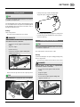
The following load attachment points are provided on the
rotary harrow for loading with a crane:
2
2
1
- Bracket of 3-point attachment (1)
- Left and right outside on the frame of the trailing roller
(2)
(Rotary harrows overall weight see section entitled
"Technical Data")
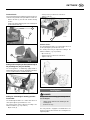
Preparing for hitching to the tractor
Adjust the lower link brackets of your rotary harrow to the
mounting bracket category of your tractor.
Category II:
Interchange the lower link brackets of your mounting bracket
so that the rocker is inside. Insert the pin with the small
end (KAT II) into the rocker.
Category III:
Interchange the lower link brackets of your mounting
bracket so that the rocker is outside. Insert the pin with
the big end (KAT III) into the rocker.

- 11 -
1800-EN_Anbau_8773
HITCHING THE IMPLEMENT EN
Safety advice
NOTE
Property damage - in the event of a collision between
cardan shaft and machine.
• Check the length of the cardan shaft before
fi rst use.
• Adjust the length of the cardan shaft if
necessary. For details see chapter “Cardan
shaft” in the attachment of this Operating
Instructions.
TIP
The general safety information in the Attachment to the
Operating Instructions is to be observed!
Hitching the implement
Requirement:
Check the suitability of your tractor according to the section
located in the attachment entitled “Important Additional
Information for Your Safety” before attaching the rotary
harrow to the tractor.
WARNING
Risk of serious injury - by squeezing or body parts
being trapped between tractor and machine!
• Please relegate every person from the
danger area of the coupling points on the
machine before driving up the tractor to the
machine.
Hitching:
- Prepare the tractor lifting mechanism according to the
Chapter "Tractor requirements"
WARNING
Risk of serious injury - by squeezing or body parts
being trapped between tractor and machine!
• Secure the tractor against rolling
• Stop the engine.
• Remove the key
before making the danger area between tractor and
machine accessible again.
345
- Connect and secure lower linkage to the pendular
compensators (3). The pendular compensators (3) can
be moved horizontally via the hole pattern (5) and are
to be adapted to the tractor.
- Connect upper link and secure. (4)
- Connect cardan shaft.
The overload security of the cardan shaft is to be coupled
with the connection of the accessory equipment
- Connect the 7-pin plug of the lighting to the tractor.
- Connect the hydraulic hoses depending on equipment.
WARNING
Risk of serious injury - by squeezing or body parts
being trapped between tractor and machine!
• Please relegate every person from the
danger area of the coupling points on the
machine before operating the hydraulic lift of
the tractor.

- 12 -
1800-EN_Anbau_8773
HITCHING THE IMPLEMENT EN
Unhitching implement
TAKE NOTE
Property damage - due to the machine sinking on
unsuitable grounds.
• Only park the machine on fl at, fi rm ground!
Requirement:
Only park the rotary harrow on firm, level ground! Ensure
there is enough clear space to make it easy to re-attach
the rotary harrow to the tractor.
Unhitching:
- Disconnect the 7-pin plug of the lighting at the tractor.
- Disconnect hydraulic hoses depending on equipment.
- Disconnect cardan shaft
- Relieve and disconnect upper linkage.
- Disconnect lower linkage and carefully drive the tractor
forwards.
- Secure implement with the anti-theft device
1. Install anti-theft device on the mounting
2. Secure the anti-theft device with a padlock.
Lower linkage mounting

- 13 -
1800-GB_Transport_8773
TRANSPORT
EN
Safety advice
DANGER
Life hazard - due to falling off from the implement
during the drive.
• Do not give permission to anyone to ride on
the rotary harrow or to climb on the running
rotatary harrow.
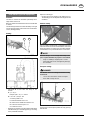
transport position
TIP
Observe the country-specific regulations! (especially for
the transport width of LION 353.14 WG and of the LION
403 WG when hitched!)
See Attachment C - statutory information on hitched
implements drawn by towing vehicles in road traffic.
Requirement:
The transport width of the rotary harrow LION 303 can
be reduced to less than 3 m. The transport height varies
depending on equipment.
Adjusting to transport height:
Version WG:
- Unlock, fold up and secure the side sheets (1).
- Check the functioning of the lighting or, for
- LION 353.14 and LION 403: e.g. load on the trailer
1
Version classic:
- Unlock, fold up the side sheets (1) and secure for (2).
- Check the functioning of the lighting
2
1
Row markers (optional) only for version WG
- Swivel up the row markers and secure (2).
(For details see Chapter "Row markers")
2
TIP
For the version with hydraulic upper link, the sowing
machine can be inclined to the front. Thus the gravity
centre of the tractor-trailer combination is moved in the
direction of the tractor.

- 14 -
1800-GB_Transport_8773
TRANSPORT
EN
Variant: Hitched or attached seed drill
- The hitched or attached seed drill may increase the
transport dimension of the overall working unit.
- The transport information for the hitched or attached
seed drill must also be observed.
(see Operating Instructions "Seed drill")
- for the attached seed drill with hydrolift and lifting limiter
the lifting limiter is to be locked in transport position.
Close ball cock (3)
- Reopen the ball cock (3) in working position to allow
the function of the lifting limiter
3

- 15 -
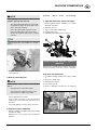
1800-GB_Settings_8773
SETTINGS
EN
Rotor Speed
Requirement:
The speed of the rotors may be pre-selected depending on
the tractor power and ambient conditions. This is carried
out either by way of the pre-selected PTO drive shaft speed
of the tractor or by the position of the gearwheels in the
rotary harrow’s transmission.
PTO shaft speed:
The recommended speed of the tractor’s PTO drive shaft
is 1,000 rpm. The lowest torque occurs at this speed and
this protects the drive components.
The speed of the tractor’s PTO drive shaft may be reduced
to 750 rpm or 540 rpm on soft ground or with a low working
depth.
Reposition the gears in the transmission of the
rotary harrow (only version WG):
- Lift the rotary harrow and incline it with the upper link
as much as possible to minimise oil leakage.
DANGER
Risk of death - in the event of unpredictable
movements of tractor or machine
• Secure the tractor against unintentional
rolling.
• Stop the engine.
• Remove the key.
• Secure the machine against falling with
support elements (1).
1
NOTE
Material hazard - due to leaking oil
• Before opening the transmission cover put
a tub underneath the transmission to collect
any possibly leaking oil.
TAKE NOTE
Material hazard - due to staining of the gear
• When the transmission is open, pay atten-
tion to cleanliness and to not let any dirt
inside the transmission.
- Unscrew the transmission cover (2).
2
- Insert the gears according to the table above.
- Screw the transmission cover (2) and check that it is
tight.
- Check the transmission oil level and if necessary refill.
(For details see chapter "Maintenance")
Table: Rotations of the spin top during the
articulated shaft rotations: (only version classic)
Transmission classic:
U/min articulated
shaft
U/min spin top at
transmission rotation:
540 185
750 257
1,000 342

- 16 -
1800-GB_Settings_8773
SETTINGS
EN
Working depth
TIP
It is recommended that the adjustment devices are cleaned
to facilitate the adjustments.
The working depth of the rotary is determined by the pivot
arc of the attached roller. The pivot arc is limited upwards
by the marking position of the bolts in the frame’s hole on
the right and left-hand sides.
Setting:
-Raise rotary harrow
The roller lowers and the bolts are relieved.
DANGER
Risk of death - in the event of unpredictable
movements of tractor or machine
• Secure the tractor against unintentional
rolling.
• Stop the engine.
• Remove the key.
• Secure the machine against falling with
support elements (1).
1
- Release the bolts (2) and lock in the required position.
TIP
The working depth closely depends on the soil conditions.
2
Lowest position (A)= smallest working depth
Top position (B) = greatest working depth
173-12-02
A
B
The working depth changes by approx. 2.5cm per hole
- Lock the bolts (2) left and right at the same position!
- Secure the bolts (2).
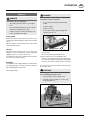
Scraper plate of the rollers
TIP
It is recommended that the adjustment devices are cleaned
to facilitate the adjustments.
The scraper plates clean the rollers of dirt.
Setting:
(for all rollers with wiper except for cutting packing rollers)
-Raise rotary harrow
The roller is free and the roller freewheel can be tested.
DANGER
Risk of death - in the event of unpredictable
movements of tractor or machine
• Secure the tractor against unintentional
rolling.
• Stop the engine.
• Remove the key.
• Secure the machine against falling with
support elements (1).
1

- 17 -
1800-GB_Settings_8773
SETTINGS
EN
- Loosen bolts (2) on both sides
- The wear of the scraper plates can be re-adjusted with
the bolt (3).
- Re-tighten bolts (2) !
23
TIP
Only re-adjust the scraper plates to the extent that the
freewheel of the roller is not hindered by the scraper
plate. If necessary, the scraper plates can be adjusted
individually, by loosening the bolt (4) and moving the
scraper plate in the slot.
4
Setting:
for the cutting packing rotor
1. Loosen bolts (6) (7)
2. Using a lever (e.g.: screw driver) in bush (5) turn the
bar at the pivot point (7).
3. Re-tighten bolts (6) (7).
5
7
6
TIP
Only re-adjust the scraper plates to the extent that the
freewheel of the roller is not hindered by the scraper
plate. If necessary, the scraper plates can be adjusted
individually, by loosening the bolt (4) and moving the
scraper plate in the slot.
4
Side boards
DANGER
Life hazard - due to side shields not being folded
down properly
• First, fold down the side shields and only
then switch on the motor of the drive.
• Please always repair faulty side shields.
The side shields screen access to the outer processing tines
in the working position and support preparation of the seed
bed in that the soil processed cannot escape to the side.
Changing from working into transport position:
Version WG:
The side shields may be pivoted into the transport position to
reduce the rotary harrow’s transport width to less than 3 m.
- Remove the bolts (1) from the side shield
- Lift the side shield completely and secure it in transport
position with the bolts (1)
1

- 18 -
1800-GB_Settings_8773
SETTINGS
EN
Version Classic:
The side shields may be pivoted into the transport position to
reduce the rotary harrow’s transport width to less than 3 m.
- Remove the bolts (1) from the side shield in working
position
- Lift the side shield completely and secure it in transport
position with the bolts (2)
2
1
2
Setting of the transport position with the help of
the parallelogram: (only version WG)
The shield guidance is additionally equipped with a
parallelogram if the rotary harrow is fitted with a row marker
or if it is combined with a seed drill attachment.
Setting the shield height in working position:
Version WG:
The shield height should be set so that it slides about 1-2
cm deep through the ground when it is used.
The shield position may be adjusted according to the
ambient conditions (e.g. crop residues).
- Open screws (2)
- Set the position you wish in the slotted hole
- Tighten screws (2)
2
Version classic:
The shield height should be set so that it slides about 1-2
cm deep through the ground when it is used.
The shield position may be adjusted according to the
ambient conditions (e.g. crop residues).
- Open screws (2)
- Set the position you wish in the slotted hole
- Tighten screws (2)
2
Levelling bars
DANGER
Danger to life due to moving gyros during work on
the levelling bar
• Switch off the motor before working on the
levelling bars.
• Remove the key.
The rotary harrow is equipped as standard with a rear
bar and on request with a front bar. The levelling bars are
height adjustable.

- 19 -
1800-GB_Settings_8773
SETTINGS
EN
Setting trimming bar:
- Take the cam lever (auxiliary means for easier
adjustment) from the parking position (1)
1
- Insert the can lever (2) in the first free hole on the
levelling bar arm and swivel until the bolt (3) is free of
load and can be taken out.
3 2
- Continue lever swivelling until the levelling bar can be
taken out through the next hole with the bolt (3).
- Repeat the procedure until the levelling bar has reached
the chosen position.
- Take out the cam lever and place it in parking position
(1)
Setting front bar:
- Like with the trimming bar, follow the holes on the
levelling bar arm (4)
4
Hydraulic upper link (optional
equipment)
Operation:
- by means of the double-acting hydraulic system of the
tractor set the inclination angle of the sowing machine.
- On headlands you can lift the sowing machine separately
so as to permit field harrowing without sowing.
- In road transport position the gravity centre of the trailer
can be moved in the direction of the tractor by further
inclining the sowing machine in driving direction.
Setting the inclination of the drill
The drill should be standing horizontally or slightly to the
back. To do that, adjust the length of the upper link via the
spindle on the hydraulic cylinder.
Setting:
1. Unhitch harrow from drill (see unhitching of the drill)
2. Remove linchpin (1)
3. Remove bolt (2)
1
2
4. Fold up the upper link
5. Fold away the upper link arm so that the counternut
(3) and the square shaft are easily accessible.
6. Open the counternut (3)
7. Set the spindle length by rotating the rear end (4).
Distance A (between the rear lifting cylinder and the
counternut) must be between 40 mm and 65 mm.
A
3
4
The bigger distance A the more the drill inclines to
the back, in driving direction.
The smaller the distance A the more the drill inclines
to the front, in driving direction.

- 20 -
1800-EN_Einsatz_8773
OPERATION
EN
Operation
DANGER
Life hazard - due to moving parts
• Check the protective devices for complete-
ness.
• First, fold down all protective devices prop-
erly before switching on the drive
• Instruct everyone to leave the danger area
before switching on the drive.
Starting work:
On the field, lower the rotary harrow to just above the soil
and only then bring the PTO drive shaft up to the intended
speed.
Approach with the tractor and lower the rotary harrow
completely whilst doing so.
Turning:
Only raise the rotary harrow as far as necessary for the
turning procedure. If the PTO drive shaft is only angled
slightly in the process, it may continue to run.
The PTO drive shaft must be switched off if the machine
runs noisily in the raised condition.
Blockages:
The PTO drive shaft is equipped with an overload clutch to
intercept any blockages on stony ground or other obstacles
without damaging the rotary harrow.
Removing blockages:
DANGER
Risk of death - in the event of unpredictable
movements of tractor or machine
• Secure the tractor against unintentional
rolling.
• Stop the engine.
• Remove the key.
• Secure the machine against falling with
support elements (1).
1
- stop the tractor
- raise the rotary harrow and simultaneously
lower the rotational speed of the PTO drive shaft.
If the rotors are free from blockages, the cam-type cut-
out clutch of the PTO drive shaft engages again audibly
due to the reduced speed, and work can be continued.
The rotors must be freed of the blockage or obstacle if they
do not start to rotate.
CAUTION
Mild injury risk - due to thrown off parts which are
not covered by the protective cover.
• Refer people out of the danger area.
• Stop drive of the machine as soon as any-
body approaches it.
La pagina sta caricando ...
La pagina sta caricando ...
La pagina sta caricando ...
La pagina sta caricando ...
La pagina sta caricando ...
La pagina sta caricando ...
La pagina sta caricando ...
La pagina sta caricando ...
La pagina sta caricando ...
La pagina sta caricando ...
La pagina sta caricando ...
La pagina sta caricando ...
La pagina sta caricando ...
La pagina sta caricando ...
La pagina sta caricando ...
La pagina sta caricando ...
La pagina sta caricando ...
La pagina sta caricando ...
La pagina sta caricando ...
La pagina sta caricando ...
La pagina sta caricando ...
La pagina sta caricando ...
La pagina sta caricando ...
La pagina sta caricando ...
La pagina sta caricando ...
La pagina sta caricando ...
La pagina sta caricando ...
La pagina sta caricando ...
-
 1
1
-
 2
2
-
 3
3
-
 4
4
-
 5
5
-
 6
6
-
 7
7
-
 8
8
-
 9
9
-
 10
10
-
 11
11
-
 12
12
-
 13
13
-
 14
14
-
 15
15
-
 16
16
-
 17
17
-
 18
18
-
 19
19
-
 20
20
-
 21
21
-
 22
22
-
 23
23
-
 24
24
-
 25
25
-
 26
26
-
 27
27
-
 28
28
-
 29
29
-
 30
30
-
 31
31
-
 32
32
-
 33
33
-
 34
34
-
 35
35
-
 36
36
-
 37
37
-
 38
38
-
 39
39
-
 40
40
-
 41
41
-
 42
42
-
 43
43
-
 44
44
-
 45
45
-
 46
46
-
 47
47
-
 48
48


Pottinger LION 253 CLASSIC Istruzioni per l'uso
- Tipo
- Istruzioni per l'uso
- Questo manuale è adatto anche per
in altre lingue
Documenti correlati
-
Pottinger TOP 692 A Istruzioni per l'uso
-
-
-
-
-
-
-
-
-