
Manuale installatore - Installer guide
Manuel installateur - Technisches Handbuch
Instrucciones instalador - Manual do instalador
Art. 6621 (6621/F), 662C (662C/F), 6721 (6721/F), 6721/FD**
Videocitofono incasso Due Fili / Videocitofono tavolo Due Fili / Videocitofono parete Due Fili
Due Fili flush-mount monitor / Due Fili desktop monitor / Wall monitor Due Fili
Portier-v encastr. Due Fili / Portier-v de table Due Fili / Portier-v saillie Due Fili
UP-Videohaustelefon DueFili / Videohaustelefon Tischgerät DueFili / AP-Monitor Due Fili
Videoportero de empotrar Due Fili / Videoportero sobremesa Due Fili / Videoportero sup. Due Fili
Video porteiro de embeber Due Fili / Video porteiro montagem saliente Due Fili / Video porteiro de mesa Due Fili
6600
*

2
6600
G) Pulsante : per apertura serratura e termina anche l’eventuale con-
versazione in corso.
H) Pulsante
: per l’autoaccensione del videocitofono senza essere
stato chiamato.
I)
Pulsante parla/ascolta bicanale: dopo la chiamata e/o l’accensione
del monitor
premere una volta per attivare la conversazione. Ripremendolo
una seconda volta la conversazione viene terminata. Durante la conversa-
zione il LED rosso rimane acceso.
L) Segnalazione porta aperta: l’accensione della segnalazione
(LED verde) indica che almeno una porta è aperta.
Spenta quando tutte le porte sono chiuse (la funzione è opzionale in
relazione al tipo di installazione).
M)
Segnalazione chiamata esclusa: l’accensione della segnala-
zione (LED rosso) indica che la chiamata è esclusa (vedi punto E).
Il LED rosso rimane acceso anche per tutta la durata della conversa-
zione, cioè fino a che la fonica è attiva.
N.B. I videocitofoni Art. 6621, 6721 dispongono sul retro del pulsante di
RESET per le fasi di programmazione, mentre nel videocitofono Art. 662C
il pulsante di RESET è nel fondo della base da tavolo e tutti dispongono di
connettori A-B-C per la stabilizzazione del segnale video e di una regola-
zione del colore.
DESCRIZIONE
Gli Art. 6621 (6621/F), 662C (662C/F), 6721 (6721/F) sono videocitofoni
vivavoce della serie 6600 con schermo a colori, utilizzabili per impianti
videocitofonici Due Fili Plus.
Le versioni Art. .../F, hanno le stesse caratteristiche e non presentano dif-
ferenze nell’installazione e programmazione.
Lo schermo di tutti i videocitofoni sopraelencati è inclinabile verticalmente.
Essi sono forniti di serie di 8 pulsanti, uno per l’apertura della serratura, uno
per l’autoaccensione del videocitofono nell’impianto anche quando non è
stato chiamato, uno per la conversazione, uno per servizio luce scale, due
per le regolazioni del volume interno della fonica e del volume suoneria e
due per selezione del tipo suoneria. Le segnalazioni luminose di: chiamata
esclusa, chiamate inevase senza risposta, servizi non disponibili e porta/
cancello aperto, sono segnalate tramite i due LED (rosso e verde) presenti
nel videocitofono.
- L’installazione del videocitofono da incasso parete (Art. 6621) richiede
la scatola da incasso Art. 6149 o le staffe Art. R660 nel caso di installa-
zione su pareti tipo cartongesso.
- L’installazione del videocitofono da esterno parete (Art. 6721) richiede la
staffa per fissaggio a parete fornita di serie.
L’Art. 6721/FD è predisposto per l’utilizzo con gli apparecchi acustici delle
persone audiolese. Per attivarlo, selezionare la posizione “T” dell’appare-
cchio acustico.
A
B
E
H
I
D
E
D
F
G
C
L
M
Fig. 1
Fig. 2
Montaggio da
incasso parete
59mm
10mm
141mm
139
mm
136
mm
141mm 125mm
125
mm
40mm
141mm
139
mm
Part. 1
Morsettiera di collegamento e connettori
+12, CH) Collegamento suoneria supplementare.
1, 2) Linea BUS.
E+, E- ) Alimentazione supplementare per videocitofono con alimenta-
tore Art. 6923.
FP, M) Collegamento per pulsante di chiamata fuoriporta.
INSTALLAZIONE Art. 6621
- Installare il videocitofono lontano da fonti lu mi no se e di calore.
- Incassare la scatola Art. 6149 al muro ad un’altezza di circa 1,40 m dal
pavimento.
- Togliere il traversino in plastica dalla scatola (vedi Part. 1 di Fig. 2)
- Eseguire i collegamenti della morsettiera (vedi schemi di collegamento)
- Fissare il videocitofono alla scatola tramite le 4 viti in dotazione (Fig. 2).
- Inserire le mascherine laterali, facendo attenzione che quella con la fes-
sura per il microfono, va inserita a destra (fig. 2).
Caratteristiche tecniche videocitofono
- Videocitofono in ABS.
- Morsettiera estraibile.
- Monitor 3,5” a schermo piatto.
- Circuito elettronico su schede intercambiabili.
- Segnale video standard PAL.
- Temperatura di funzionamento da 0° a +40° C.
- Suoneria elettronica.
- Ingresso per chiamata fuori porta con suoneria distinta dalla chiamata da
targa.
- Uscita per suoneria supplementare Art. 860A.
- Alimentazione data dal bus.
- Ingresso per alimentazione supplementare (Art. 6923) nel caso che l’im-
pianto sia configurato per permettere l’accensione di più di due monitor
contemporaneamente.
Controlli e regolazioni
A) Schermo 3.5” inclinabile manualmente.
B) Microfono.
C) Altoparlante.
D)
Coppia di pulsanti.
1) Quando il monitor è acceso i pulsanti permettono la regolazione della
luminosità.
2) Quando il monitor è spento i pulsanti permettono la selezione della melodia
per la sola chiamata da posto esterno. Per programmare la melodia: mante-
nere premuto per almeno 2 secondi uno dei 2 pulsanti, ripremere ripetutamente
i pulsanti per selezionare la melodia interessata.
E) Coppia di pulsanti.
1) In conversazione con il pulsante “I” premuto, premere i pulsanti “E” per
aumentare o diminuire il volume della fonica interna.
2) A riposo regolano il volume della suoneria: mantenere premuto per al-
meno 2 secondi uno dei 2 pulsanti “E”, premere ripetutamente i pulsanti per
aumentare o diminuire oppure escludere il volume della suoneria. I pulsanti
“E” regolano il volume suoneria anche durante l’immissione del suono di
chiamata interna o esterna. Terminata l’emissione del suono, regolano il
contrasto mentre lo schermo è acceso.
F) Pulsante :
per servizio ausiliario, 1° relè del 1° attuatore art. 69RH.
IT

3
6600
3
2
1
INSTALLAZIONE Art. 6621 CON LE STAFFE Art. R660
- Installare il videocitofono lontano da fonti luminose e di calore.
- Praticare un foro nella parete in cartongesso di 120x120mm ad una al-
tezza di circa 1,40m dal pavimento al bordo inferiore.
- Fissare le staffe al videocitofono come indicato in figura, tenendo i cursori
allineati ai fianchi del videocitofono (Part. 1, Fig. 2A).
- Eseguire i collegamenti della morsettiera (vedi schemi di collegamento)
- Inserire il videocitofono all’interno della parete in cartongesso.
Avvitando i cursori devono muoversi in modo perpendicolare rispetto al
videocitofono (vedi Part. 1 Fig. 2A).
- Inserire le mascherine laterali, facendo attenzione che quella con la fes-
sura per il microfono vada inserita a destra.
Fig. 2A
1
2
3
4
Fig. 2B
Montaggio da
esterno parete
59mm
10mm
141mm
139
mm
136
mm
141mm 125mm
125
mm
40mm
141mm
139
mm
INSTALLAZIONE Art. 6721
- Installare il videocitofono lontano da fonti luminose e di calore.
- Fissare la piastra di aggancio del videocitofono ad una altezza di 1,40m
dal pavimento al bordo inferiore.
- Eseguire i collegamenti della morsettiera (vedi schemi di collegamento)
- Inserire il videocitofono seguendo il senso delle frecce 1 e 2.
- Per togliere il videocitofono dalla piastra di aggancio, agire con un cac-
ciavite sulla linguetta di sicurezza (posta sopra e dietro al videocitofono)
ed estrarlo seguendo il senso delle frecce 3 e 4.
Fig. 2C
Montaggio
da tavolo
59mm
10mm
141mm
139
mm
136
mm
141mm 125mm
125
mm
40mm
141mm
139
mm
INSTALLAZIONE Art. 662C
- Fissare la borchia alla parete
- Eseguire i collegamenti della morsettiera (vedi schemi di collega-
mento).
- Inserire la presa nella borchia
IT

4
6600
Terminazione Bus per stabilizzazione del
segnale video
All’interno del citofono è presente un “con-
nettore di terminazione BUS” (A-B-C) per la
stabilizzazione del segnale video.
A seconda della configurazione di collega-
mento (citofoni/videocitofoni collegati in serie
o derivati ad un distributore) settare in ponti-
cello sul connettore ABC come descritto nella
nota “Terminazione bus” riportata in seguito,
nella sezione schemi di collegamento.
Fig. 3
B
A
A
A
Art. 6621
Art. 6721
Art. 662C
PROGRAMMAZIONE
Le programmazioni del videocitofono sono di tre tipi:
- Assegnazione codice identificativo o codice di chiamata (indispensabile)
- Assegnazione codice identificativo secondario (per videocitofoni asso-
ciati ad un citofono/videocitofono di “capogruppo”).
- Programmazione pulsanti per servizi ausiliari e chiamate intercomuni-
canti (dove necessario)
Le programmazioni devono essere effettuate con l’impianto acceso, senza
comunicazioni attive e solamente dopo aver collegato i citofoni/videocito-
foni all’impianto e programmato le targhe.
Programmazione codice identificativo
Il codice identificativo va programmato per mezzo di una targa (principale
-”MASTER”), presente nell’impianto già configurata. Il videocitofono viene
fornito senza codice identificativo associato. Per verificare ciò premere il
pulsante “G” e il videocitofono emetterà un triplo “Bip”.
Attenzione: durante la programmazione del codice di identificazione
del videocitofono si hanno a disposizione 30 secondi dal momento in
cui si entra in programmazione nel videocitofono al momento in cui si
preme il pulsante di chiamata sulla targa o si invia il codice.
Fase di programmazione
1) Premere e tenere premuto “I”
2) Successivamente premere e tenere premuto anche “H” insieme ad “I”
3) Attendere 3 secondi circa fintanto che il LED rosso “M” inizia a lampeg-
giare.
4) A questo punto il microprocessore si è fisicamente resettato.
5) Rilasciare entrambi i pulsanti “I” e “H”. A questo punto si hanno 5 se-
condi circa per eseguire una qualsiasi delle programmazioni descritte.
6) Premere e mantenere premuto il pulsante “G”
7) Dopo circa 2 secondi il videocitofono emette un suono acuto, si auto-
accende e si mette in conversazione con la targa.
8) Nelle targhe a pulsanti premere il pulsante di chiamata corrispondente
al videocitofono. Nelle targhe alfanumeriche comporre il codice di chia-
mata e premere il pulsante “
”.
9) Se nell’impianto esiste già un citofono/videocitofono con lo stesso co-
dice identificativo associato, la targa emette un segnale sonoro basso
ed è necessario ripetere l’operazione dall’inizio.
10) In caso contrario il codice viene associato al videocitofono e la comu-
nicazione viene terminata.
Programmazione codice identificativo secondario
La programmazione del codice identificativo secondario è richiesta sola-
mente quando si vuole far suonare contemporaneamente più di un cito-
fono/videocitofono con lo stesso pulsante o codice di chiamata. I citofoni/
videocitofoni che devono suonare contemporaneamente vengono associati
con lo stesso pulsante ad uno stesso gruppo. Il citofono/videocitofono di
“capogruppo” viene programmato per primo attraverso la precedente pro-
cedura “programmazione codice identificativo”. I citofoni/videocitofoni ag-
giuntivi vengono programmati con il codice identificativo secondario (vedi
tabella riportata nella sezione schemi di collegamento allegati alle targhe
elettroniche DUE FILI ELVOX).
Il numero di citofoni/videocitofoni che si possono associare ad uno stesso
gruppo, senza l’ausilio del programmatore Art. 950C o SaveProg, sono tre
e un capogruppo.
Fase di programmazione:
1) Premere e tenere premuto il tasto “I”
2) Successivamente premere e tenere premuto anche “H” insieme ad “I”.
3) Attendere 3 secondi circa fintanto che il LED rosso “M” inizia a lampeg-
giare.
4) A questo punto il microprocessore si è fisicamente resettato.
5) Rilasciare i pulsanti “I” e “H“.
6)
Premere contemporaneamente e mantenere premuti i pulsanti “G” e “H”.
7) Dopo 2 secondi il citofono emette un tono acuto e viene messo in co-
municazione con la targa
8) Rilasciare i punti “G” e “H”
9) Nelle targhe a pulsanti premere il pulsante di chiamata corrispondente
al citofono/videocitofono di capogruppo. Nelle targhe alfanumeriche
comporre lo stesso codice di chiamata del citofono/videocitofono di
capogruppo e premere il pulsante “
”.
10) Se nell’impianto esiste già un citofono/videocitofono con lo stesso co-
dice identificativo associato, la targa emette un segnale sonoro basso
ed è necessario ripetere l’operazione dall’inizio.
11) Associato l’identificativo secondario al videocitofono, la comuni-
cazione viene terminata.
Per conoscere il numero assegnato fare riferimento alla tabella riportata
nella sezione schemi di collegamento.
IT

5
6600
FUNZIONAMENTO
Le chiamate da targa esterna, intercomunicanti e fuoriporta sono differen-
ziate tra loro da toni diversi.
Chiamata da targa.
Le chiamate da targa non seguono la pressione del pulsante di chiamata
ma vengono generate internamente dal videocitofono. Il periodo di chia-
mata o ciclo di chiamata è 1 secondo di suono e 2 secondi di pausa ripetuto
per 2 volte (valore di default impostato nella targa). La durata delle suonerie
di tipo “Din-Don” e “Din-Don-Dan” non segue il tempo imposto dal ciclo di
chiamata ma segue il tempo naturale della suoneria.
Per rispondere, premere e rilasciare il pulsante “I”. Se il pulsante “I” è già
premuto durante la chiamata rilasciarlo e ripremerlo. Il tempo di risposta
alla chiamata (30 s) e il tempo di conversazione (2 minuti di default) sono
impostati nei parametri della targa. Scaduto il tempo di conversazione, si
può continuare, se viene eseguita di nuovo la chiamata entro 10 s dalla
stessa targa.
Durante la conversazione si può interrompere momentaneamente la fonica
(5 s massimo), premendo il pulsante “I”.
Per riprendere la conversazione ripremere il pulsante “I” entro 5 s, altri-
menti la comuncazione decade.
Per terminare la conversazione premere il pulsante “I”. Durante il tempo
nel quale la fonica è attiva, rimane acceso il LED rosso “M” rimane acceso.
Chiamata intercomunicante.
Premere il pulsante intercomunicante, se programmato, relativo al citofono/
videocitofono da chiamare. Dall’altoparlante del videocitofono chiamante si
udrà un tono di chiamata (se la chiamata è possibile) o tono di occupato
(se la chiamata non è possibile). Nel citofono/videocitofono chiamato la
suoneria inizierà a suonare ciclicamente con un ritmo di 1 s di suono e
4 s di pausa. La durata massima della chiamata sarà di 30 s (6 cicli). Se
si desidera interrompere la chiamata, premere il pulsante “I” prima che il
chiamato risponda. Per rispondere alla chiamata, dal videocitofono chia-
mato sollevare il microtelefono o premere il pulsante “I”. Alla risposta il
videocitofono sarà messo direttamente in comunicazione con il chiamato.
La durata massima della conversazione è di 5 minuti. Scaduto il tempo di
conversazione si può continuare la conversazione, se viene eseguita di
nuovo la chiamata entro 10 s. Un’eventuale chiamata da targa ha priorità
su quella intercomunicante.
Chiamate rifiutate.
L’esclusione della suoneria è indicata dall’accensione permanente del LED
rosso “M”. Se vengono eseguite delle chiamate da targa verso il videocito-
fono quando è in condizione di chiamata esclusa, queste vengono rifiutate.
Il rifiuto delle chiamate determina un breve spegnimento del LED rosso
“M” tante volte quante sono le chiamate escluse (fino ad un massimo di
4 chiamate). La segnalazione viene ripetuta ogni 10 s circa. La cancella-
zione delle chiamate rifiutate avviene con: la riabilitazione della suoneria,
con il RESET del videocitofono o l’assenza di alimentazione nell’impianto.
Nelle targa il rifiuto è segnalato con il tono dissuasione (una serie di “Bip”
di 100ms con pausa di 100ms per 5 s totali). Nella targa con display viene
anche visualizzato il messaggio “Non disturbare”.
La programmazione dei Pulsanti “G” e “I” può essere modificata in due
diverse configurazioni (modalità di comunicazione “MANI LIBERE” (hands
free) oppure con pulsante parla/ascolta PREMUTO), tramite il programma-
tore Art. 950C connesso ad una targa a pulsanti e/o una targa alfanumerica
con versione software maggiore o uguale alla V4.
Vedere le istruzioni del programmatore Art. 950C e delle targhe o unità
elettroniche.
Tasto Serratura
Il tasto serratura di ogni apparecchio funziona nel modo seguente.
- Apparecchio con microtelefono a riposo serratura verso l’ultima
targa con la quale ha parlato o dalla quale è stato chiamato.
- Apparecchio con microtelefono sollevato ma non impegnato in conver-
sazione chiamata a centralino se il flag Centralino è SI. Altrimenti
si riconduce al primo caso.
- Apparecchio con microtelefono sollevato e impegnato in conversazione
interna come il primo caso
- Apparecchio con microtelefono sollevato e impegnato in conversazione
esterna o chiamato da targa serratura verso la targa con la quale
sta parlando o dalla quale è chiamato.
In pratica si va ad azionare una serratura sempre tranne quando si alza il
microtelefono e si preme subito il pulsante serratura. Portare anche questo
al caso standard si può se nell’impianto non c’è il centralino di portineria e
se si pone il flag Centralino a NO.
N.B.: nella famiglia 6600 la manovra equivalente è premere per un attimo
il pulsante vivavoce e poi serratura. Anche in questo caso viene chiamato
il centralino.
Programmazione pulsanti
Il videocitofono viene fornito con tre pulsanti per le funzioni di serratura,
autoaccensione e per il servizio ausiliario “luce scale”, il quale attiva il 1° relè
del 1° attuatore (art. 69RH), se collegato all’impianto e di altri sei pulsanti
per chiamate intercomunicanti o servizi ausiliari. Per cambiare il tipo di fun-
zionamento dei pulsanti è necessario utilizzare il programmatore art. 950C,
ad eccezione per l’assegnazione delle funzioni chiamate intercomunicanti
ed autoaccensione verso una targa specifica.
Programmazione pulsanti per chiamate intercomunicanti (Se della
serie 8870, Giotto, Petrarca, sganciare il microtelefono del citofono/
videocitofono da chiamare. Se della serie 6600 tenere premuto il pul-
sante “I”).
Fase di programmazione:
1) Premere e tenere premuto “I”.
2) Successivamente premere e tenere premuto anche “H” insieme ad “I”.
3) Attendere 3 secondi circa fintanto che il LED rosso “M” inizia a lampeg-
giare.
4) A questo punto il microprocessore si è fisicamente resettato.
5) Rilasciare i pulsanti “I” e “H“.
6) Premere e tenere premuto il pulsante da programmare “F”.
7) Dopo 2 secondi il citofono emette un tono acuto mentre l’altro citofono/
videocitofono emette una scala tritonale ascendente
8) Rilasciare il pulsante relativo alla chiamata intercomunicante “F”
9) Premere nel citofono/videocitofono chiamato (quello con il suono trito-
nale), uno dei pulsanti programmati come serratura, F1, F2 o ausiliario.
10) Un tono acuto conferma la fine della procedura. Ripetere la stessa
procedura anche per gli altri citofoni/videocitofoni ed eventuali pulsanti
di chiamata intercomunicante.
Programmazione pulsante autoaccensione verso targa specifica.
Fase di programmazione:
1) Premere e mantenere premuto “I”
2) Successivamente premere e tenere premuto anche “H” insieme ad “I”.
3) Attendere 3 secondi circa fintanto che il LED rosso “M” inizia a lampeg-
giare.
4) A questo punto il microprocessore si è fisicamente resettato.
5) Rilasciare i pulsanti “I” e “H“.
6) Premere e tenere premuto il pulsante da programmare “F”.
7) Dopo 2 secondi il videocitofono emette un tono acuto.
8) Rilasciare il pulsante “F” relativo all’autoaccensione.
9) Nelle targhe a pulsanti premere il pulsante di chiamata corrispondente
al videocitofono. Nelle targhe alfanumeriche comporre il codice di chia-
mata e premere il pulsante “
”.
10) Un tono acuto conferma la fine della procedura.
Riprogrammazione valore di default dei pulsanti.
Fase di programmazione:
1) Premere e mantenere premuto “I”
2) Successivamente premere e tenere premuto anche “H” insieme ad “I”.
3) Attendere 3 secondi circa fintanto che il LED rosso “M” inizia a lampeg-
giare.
4) A questo punto il microprocessore si è fisicamente resettato.
5) Rilasciare i pulsanti “I” e “H“.
6) Premere e tenere premuto il pulsante da riportare a default
7) Dopo 2 secondi il videocitofono emette un tono acuto.
8) Rilasciare e ripremere il pulsante da riportare a default
Cancellazione totale delle programmazioni.
Questa procedura è consigliata quando si vuole cambiare l’ID di un vi-
deocitofono precedentemente programmato e non si vuole mantenere
la programmazione di funzionamento dell’apparecchio.
Fase di programmazione:
1) Premere e mantenere premuto “I”
2) Successivamente premere e tenere premuto anche “H” insieme ad “I”.
3) Attendere 3 secondi circa fintanto che il LED rosso “M” inizia a lampeggiare.
4) A questo punto il microprocessore si è fisicamente resettato.
5) Rilasciare i pulsanti “I” e “H“.
6) Premere e tenere premuto il pulsante “H”
7) Dopo 2 secondi il videocitofono emette, per 2 secondi, un tono lungo.
8) Rilasciare il pulsante “H”
9) Durante il tono lungo premere il pulsante “G”. Se la procedura di cancel-
lazione è andata a buon fine, premendo il pulsante “G” il videocitofono
emetterà un triplo “Bip”.
IT

6
6600
DESCRIPTION
Types 6621 (6621/F), 662C (662C/F), 6721 (6721/F) are open voice moni-
tors series 6600 with LCD colour screen to be used in Due Fili Plus audio/
video entrance panel systems.
Type .../F versions have the same features and are programmed and in-
stalled in the same way.
The screen of all abovementioned monitors can be vertically sloped.
They are equipped as standard with 8 push-buttons for the following fun-
ctions: door lock release, self-start of video interphone in the system even
when it has not been called, conversation, stair light, internal voice line
volume control, ringtone volume control, brightness control and ringtone
type setting. Two LEDs (red and green) on the video interphone serve to
indicate the following states: call signal mute, unanswered calls, services
not available and gate/door open.
- Flush-mounting of the video interphone (type 6621) requires the use of
flush-mounted back box type 6149 or the brackets type R660 (for pla-
sterboard).
- The surface wall-mounted installation for the video-interphone (type
6721) requires the brackets for the wall-mounting supplied as standard.
Type 6721/FD is designed for use with hearing aids used by hearing impai-
red people. To activate it, select the “T” position on the hearing aid.
Video interphone technical specifications
- Flush-mounted video interphone in ABS.
- Removable terminal block.
- Flat 3,5” TFT LCD screen.
- Electronic circuit on interchangeable cards.
- PAL standard video signal.
- Operating temperature from 0° to +40° C.
- Electronic ringtone.
- Input for landing calls with different ringtone from entrance panel calls.
- Output for additional ringtone type 860A.
- Supply voltage provided by bus.
- Input for additional power supply (type 6923) if the system is configured
to enable simultaneous activation of more than two monitors.
Controls and adjustments
A) Manually tilting TFT 3,5” LCD screen.
B) Microphone.
C) Loudspeaker.
D)
Pair of push-buttons.
1) When the monitor is ON, the push-buttons can be used to adjust the
brightness.
2) When the monitor is OFF, the push-buttons can be used to select
the tune for calls from a speech unit only. To programme the tune:
hold down 1 of the 2 push-buttons for at least 1 second, then press the
push-buttons repeatedly to select the desired tune.
E)
Pair of push-buttons.
1) During conversation, with push-button “i” pressed, press push-buttons
“E” to increase or decrease the volume of the internal voice line.
2) To adjust ringtone volume: hold down 1 of the 2 push-buttons “E” for
at least 1 second, then press the push-buttons repeatedly to increase
or reduce ringtone volume, or mute the ringtone.
The “E” push-buttons adjust the chime volume also during the ring tone
for the internal or external call. Once the sound emission is terminated,
they adjust the contrast while the screen is turned on.
F)
Push-button for auxiliary service, 1st relay of 1st actuator type
692R
G) Push-button
: to open the lock and terminate any conversation in
progress.
H) Push-button
: for self-start of the monitor without the latter being
called.
I)
Two-channel conversation push-button: after the call and/or swi-
tch-on of the monitor press the pushbutton once to activate the audio.
Pressing it once again the conversation terminates.
The red LED remains lit for the whole conversation dwell.
L)
Door open LED: the red led is lit when at least one door/gate is
open, it turns off when all doors are close (the function is optional
according to the type of installation)
M)
’Ringtone mute’ LED: if the red LED lights up, this indicates that
the call is disabled (see point “E”).
The red LED also remains lit for the entire duration of the conversation,
i.e. while the audio is active.
N.B. On the back of the video interphones type 6621, 6721 is a RESET
push-button for use during programming, while on video interphone 662C
the RESET push-button is on the bottom of the table-top conversion kit and
all are equipped with the A-B-C connectors for stabilising the video signal
and a colour setting.
Connection and connector terminal board
+12, CH) Additional ringtone connection.
1, 2) BUS line.
E+, E-) Additional supply voltage for video interphone with power
supply type 6923.
FP, M) Connection for landing call push-button.
INSTALLATION 6621
- Install the video interphone away from sources of light and heat.
- Flush-mount back box type 6149 in the wall at a height of approximately
1.4 m above the ground.
- Remove the plastic cross-piece from the back box (see Part.1, Fig. 2)
- Carry out the terminal block connections (see wiring diagram).
-
Fix the video interphone to the back box with the 4 screws supplied (fig. 2).
- Fit the side panels, taking care that the panel with the slot for the mi-
crophone is fitted on the right (fig. 2).
Flush-
mounted
version
Fig. 2
59mm
10mm
141mm
139
mm
136
mm
141mm 125mm
125
mm
40mm
141mm
139
mm
Part. 1
A
B
E
H
I
D
E
D
F
G
C
L
M
Fig. 1
EN

7
6600
3
2
1
Table version
Surface wall-mounting
version
INSTALLATION OF TYPE 6621 WITH BRACKETS TYPE R660
- Make a 120x120mm (nearly) hole in the plasterboard wall at 1,40 from
the floor to the lower border.
- Fix the bracket to the monitor as indicated in figure, keeping the cursors
well aligned to the monitor sides (part. 1, Fig. 2A)
- Carry out the terminal block connections (see wiring diagram)
- Insert the monitor inside the wall in plasterboard.
- Tighten the screws so as the cursors can get closer to the plasterboard
wall.
- By screwing, the cursors should get aligned orthogonally to the monitor
(see part. 1, Fig. 2A)
- Insert the side grids, paying attention that the one with the slot for the
microphone must be inserted on the right.
Fig. 2A
INSTALLATION OF TYPE 6721
- Install the video interphone away from sources of light and heat.
- Fix the monitor fixing plate at 1,40m. from the ground level to the lower
border.
- Connect the terminal block.
- Insert the monitor according to the 1 and 2 arrow direction
- To remove the monitor from the plate hook, operate with a screw driver
on the security lock (placed on the upper side and behind the monitor),
and remove it according to the 3 and 4 arrow direction.
Fig. 2B
Fig. 2C
INSTALLATION OF TYPE 662C
- Fix the monitor support to the wall.
- Connect the terminal block (see wiring diagrams).
- Hook the stud to the support.
1
2
3
4
59mm
10mm
141mm
139
mm
136
mm
141mm 125mm
125
mm
40mm
141mm
139
mm
59mm
10mm
141mm
139
mm
136
mm
141mm 125mm
125
mm
40mm
141mm
139
mm
EN

8
6600
Fig. 3
B
A
A
A
Bus termination for video signal stabilisa-
tion
The interphone is provided with a “BUS termi-
nation connector” (A-B-C) for video signal sta-
bilisation.
Depending on the connection configuration
(interphones/monitors connected in series or
derived from a distributor), set a jumper on the
connector ABC as described in the note “Bus
termination” in the wiring diagrams section
below.
Art. 6621
Art. 6701
Art. 662C
PROGRAMMING
There are three monitor programming modes: assignment of an identifica-
tion code or call code (indispensable), assignment of a secondary identifica-
tion code (for video interphones associated with a master video interphone),
programming of push-buttons for auxiliary services and intercommunicating
calls (when necessary).
Programming must be performed with the system switched on, without
active communication and only after connecting the interphones/video in-
terphones to the system and programming the panels.
Programming the identification code
The identification code is to be programmed by means of an entrance panel
(main- “Master”), present on the installation and already configurated. The
video-interphone is supplied without associated identification code. To
check this, press the “G” push-button and the video-interphone will emit a
triple “Beep”.
Attention: during the interphone/video interphone identification code
programming you have 30 seconds from the moment you enter the
programming in the interphone/video interphone and the moment you
press the call push-button on the panel or you send the code.
Programming phase:
1) Press and hold down “I”.
2) Press and hold down also “H” together with “I”.
3) Wait for nearly 3 seconds until the red led “M” flashes.
4) Now the microprocessor is physically reset.
5) Release both push-buttons “I” and “H”. You have now 5 seconds to
carry out any of the described programmings.
6) Press and hold down the “G” lock push-button.
7)
After nearly 2 seconds the video-interphone emits a high-pitched tone, it
self-starts and gets in communication with the entrance panel.
8) On the entrance panels with push-buttons press the call push-button
corresponding to the video-interphone, on the alphanumeric entrance
panel, on the contrary, enter the call code and press “
”.
9)
If on the installation there is already an interphone / video-interphone with
the same associated identification code, the panel emits a low-pitched tone
and you must repeat the operation from the beginning.
10) If not, the code is associated to the video-interphone and the commu-
nication is terminated.
Programming the secondary identification code
The programming of the secondary identification code is required only when
you want more than a video- interphone to ring at the same time with the
same push-button or call code. The video-interphones which must ring si-
multaneously are associated with the same push-button to the same group.
The “master” interphone / video-interphone is programmed in first place by
means of the previous procedure: “programming the identification code”.
The additional interphones / video-interphones are programmed with the
secondary identification code (see table shown in the wiring diagram section
enclosed with the electronic TWO WIRE ELVOX entrance panels).
A maximum of three audio door entry units plus one group master can be
associated with the same group, without the need for programmer Type
950C or SaveProg.
Programming phase:
1) Press and hold down “I”.
2) Press and hold down also “H” together with “I”.
3) Wait for nearly 3 seconds until the red led “M” flashes.
4) Now the microprocessor is physically reset.
5) Release both push-buttons “I” and “H”
6) Press and hold down the “G” door lock and the “H” self-start push-but-
tons simultaneously.
7) After 2 seconds the video-interphone emits a high-pitched tone and
gets in communication with the entrance panel.
8) Release the door lock “G” and the self-start “G” push-buttons.
9) On the push-buttons entrance panels press the call push-button corre-
sponding to the main (already programmed) interphone / video-inter-
phone, on the alphanumeric entrance panel, on the contrary, enter the
same call code of the “Master” interphone / video-interphone and press
“
”.
10) If on the installation there is already an interphone / video-interphone with
the same associated identification code, the panel emits a low-pitched tone
and you must repeat the operation from the beginning.
11) Once the secondary identification code is associated to the video-inter-
phone, the communication is terminated.
To know the number assigned see table shown in the wiring diagram
section.
EN

9
6600
OPERATION
Calls from an entrance panel, intercommunicating calls and landing calls
are differentiated by means of different tones.
Landing calls
Calls from entrance panels do not follow the pressing of the call push-but-
ton but are generated internally by the video interphone. The call time dwell
or cycle consists of a ringtone of 1 second and a pause of 2 seconds,
repeated twice (default setting of entrance panel). The duration of “Ding-
Dong” and “Ding-Dong-Dang” ringtones does not correspond to the time
dictated by the call cycle but to the natural duration of the ringtone. To
answer, press and release push-button “I”. If push-button “I” has already
been pressed during the call, release it and press it again The call answer
time (30 s) and the conversation time (2 minutes by default) are set in
the entrance panel parameters. Once the conversation time has elapsed,
conversation can be continued if the call is made again within 10 s, from
the same entrance panel.
During conversation, the audio can be interrupted momentarily (maximum
5 s) by pressing the “I” push-button.To resume conversation, press the
conversation push-button again within 5 s, otherwise communication is
lost. Press push-button “I” to terminate the conversation. The red LED “M”
remains lit while the audio is active.
Intercommunicating call.
Press the intercommunicating push-button, if programmed, for the inter-
phone/video interphone to be called. The loudspeaker of the calling video
interphone will emit a ringing tone (if the call is possible) or an engaged
tone (if the call is not possible). On the called interphone/video interphone
the ringtone starts sequentially at intervals of 1 s ringing and 4 s pause.
The maximum duration of the call is 30 s (6 cycles). If you wish to inter-
rupt the call, press the conversation push-button “I” before an answer is
received from the called device. To answer a call, lift the handset on the
called interphone/video interphone, or press the conversation push-button.
When answered, the video interphone enters direct communication with
the called device. Maximum duration of conversation is 5 minutes. When
the conversation time has elapsed, the user can continue without replacing
the handset if a new call is made within 10 s. Calls from the entrance panel
have priority over intercommunicating calls.
Denied calls.
The chime exclusion is indicated by the permanent lighting of the red LED
“M”. If calls are made from the entrance panel to the video interphone when
the call mute is enabled, they are denied. A denied call causes the red LED
“M” to briefly switch off according to the number of times calls are denied
(maximum 4 denied calls). The signal is repeated every 10 s (approx.).
Deletion of denied calls is by re-enabling the ringtone, resetting the video
interphone or a system power failure. On the entrance panel, a denied call
is indicated by means of a dissuasion tone (a series of “Beeps” at 100ms
intervals with a pause of 100ms for a total of 5 s). The message “Do not
disturb” also appears on entrance panels with display. The programming
of push-buttons “G” and “I” can be changed through two different configu-
rations (“HANDS FREE” or with the speak/listen push-button PRESSED),
using the programmer type 950C connected to a push-button entrance
panel and/or an alphanumeric entrance panel with software version V4 or
bigger. See instructions for programmer type 950C and entrance panels
or electronic units.
Lock Button
The lock button of each device works in the following manner.
- Device with handset at rest lock to the last entrance panel with
which it has spoken or from which it has been called.
- Device with handset raised but not engaged in a conversation call
to switchboard if the Switchboard flag is YES. Otherwise it goes back
to the first case.
- Device with handset raised and engaged in an internal conversation
as in the first case.
- Device with handset raised and engaged in an external conversation or
called from entrance panel lock to the entrance panel being
spoken with or from which it has been called.
In practice a lock is always activated except when the handset is raised
and you immediately press the lock button. This can also be taken to the
standard case if the system has no porter switchboard and the Switchboard
flag is set on NO.
NOTE: In series 6600 the equivalent operation is to press for an instant the
“open voice” push-button and then the lock release. Also in this case the
switchboard is called.
Programming the push-buttons
The video-interphone is supplied with 3 push-buttons for the following
functions: lock release, self-start and “stair light” auxiliary service, which
activates the 1st relay of the 1st actuator (type 69HR), if connected to the
installation and with other 6 push-buttons for intercommunicating calls or
auxiliary services.
To change the operation type of push-buttons it is necessary to use pro-
grammer type 950C or SaveProg, with the exception of the assignation of
the functions for the intercommunicating calls and self-start to a specific
entrance panel.
Programming the push-buttons for the intercommunicating calls
(With series 8870, Giotto, Petrarca raise the handset of the interphone
/ video-interphone to call. On the 6600 series keep pressed the talk /
listen push-button “I”).
Programming phase:
1) Press and hold down “I”.
2) Press and hold down also “H” together with “I”.
3) Wait for nearly 3 seconds until the red led “M” flashes.
4) Now the microprocessor is physically reset.
5) Release both push-buttons “I” and “H”
6) Press and hold down the “F” push-button to be programmed.
7) After 2 seconds the video-interphone emits a high-pitched tone, while
the other interphone / video-interphone emits a three-tone ascending
scale.
8) Release the “F” push-button related to the intercommunicating call.
9) On the called interphone / video-interphone (the one with the three-
tone scale) press one of the push-buttons programmed as door lock or
F1 or F2 or the auxiliary one.
10) A high-pitched tone confirms the end of the procedure.
Repeat the procedure also for the other interphones / video-interpho-
nes ad possible intercommunicating call push-buttons.
Programming the self-start push-button to a specific entrance panel.
Programming phase:
1) Press and hold down “I”.
2) Press and hold down also “H” together with “I”.
3) Wait for nearly 3 seconds until the red led “M” flashes.
4) Now the microprocessor is physically reset.
5) Release both push-buttons “I” and “H”
6) Press and hold down the “F” push-button to be programmed.
7) After nearly 2 seconds the video-interphone emits a high-pitched tone.
8) Release the push-button “F” related to the self-start.
9) On the entrance panels with push-buttons press the call push-button
corresponding to the video -interphone; on the alphanumeric entrance
panel, on the contrary, enter the call code and press “
”.
10) A high-pitched tone will confirm the end of the procedure.
Restoring the default values of push-buttons
Programming phase:
1) Press and hold down “I”.
2) Press and hold down also “H” together with “I”.
3) Wait for nearly 3 seconds until the red led “M” flashes.
4) Now the microprocessor is physically reset.
5) Release both push-buttons “I” and “H”
6) Press and hold down the push-button to be restored to its default set-
ting.
7) After 2 seconds the video-interphone emits a high-pitched tone.
8) Release the push-buttons and press again the push-button to restore
to its default setting.
Deleting all settings
This procedure is recommended when you want to change the ID of
a previously programmed video-interphone without retaining its pro-
gramming parameters.
Programming phase:
1) Press and hold down “I”.
2) Then press and hold down also “H” together with “I”.
3) Wait for nearly 3 seconds until the red led “M” flashes.
4) Now the microprocessor is physically reset.
5) Release both push-buttons “H” and “I”
6) Press and hold down the self-start push-button “H”.
7) After 2 seconds the video-interphone emits a continuous tone for two
seconds.
8) Release the self-start push-button “H”.
9) During the long tone press the lock push-button “G”.
If the deletion procedure was successful, press the lock push-button
“G” and the video-interphone will emit a triple “BEEP”.
EN

10
6600
DESCRIPTION
Les Art. 6621 (6621/F), 662C (662C/F), 6721 (6721/F) sont des moniteurs vive
voix de la série 6600 avec écran LCD 4’’ en couleurs et peuvent être utilisées
dans des installations de portiers audio/vidéo à
Due Fili Plus
. Les versions
Art. .../F ont les mêmes caractéristiques et ne présentent pas de différences
lors de l’installation et de la programmation.
L’écran de tous les moniteurs susdits est inclinable verticalement.
Ils sont fournis de série de 8 boutons-poussoirs, un pour l’ouverture de
la gâche, un pour l’auto-allumage du portier-vidéo sur l’installation même
quand il n’a pas été appelé, un pour la conversation, un pour le service
éclairage escaliers, deux pour le réglage du volume interne du son et du
volume de la sonnerie et deux pour le réglage de la luminosité et du type
de sonnerie. Les signalisations lumineuses d’appel exclu, d’appel sans
réponse, de services non disponibles et de porte/portail ouvert sont as-
surées par deux LED (rouge et verte) incorporées dans le portier-vidéo.
L’installation du portier-vidéo encastré (Art. 6621) nécessite l’utilisation
des boîtiers d’encastrement art. 6149, ou les étriers Art. R660 (pour placo
plâtre). L’installation du portier-vidéo en saillie (Art. 6721) nécessite l’utili-
sation de l’étrier (fourni de série) pour la fixation à la paroi.
L’Art. 6721/FD est prédisposé pour l’emploi avec les appareils acoustiques
des personnes malentendantes. Pour l’activer, sélectionner la position “T”
de l’appareil acoustique.
Caractéristiques techniques du portier-vidéo
- Portier-vidéo en ABS.
- Bornier extractible.
-
Moniteur TFT LCD 3,5” à écran plat.
- Circuit électronique sur cartes interchangeables.
- Signal vidéo standard PAL.
- Gamme de température de fonctionnement de 0° à +40°C.
- Sonnerie électronique.
- Entrée pour appel de palier avec sonnerie différente de l’appel de la pla-
que de rue.
- Sortie pour sonnerie supplémentaire art. 860A.
- Alimentation fournie par bus.
-
Entrée pour alimentation supplémentaire (art. 6923) dans le cas d’un sy-
stème prévoyant l’allumage de plus de deux moniteurs simultanément.
Contrôle et réglages
A) Écran avec moniteur TFT LCD 3,5”, inclinable manuellement.
B) Microphone.
C) Haut-parleur.
D)
Paire de boutons-poussoirs
1) Lorsque le moniteur est allumé, les boutons-poussoirs permettent de
régler la luminosité.
2) Lorsque le moniteur est éteint, les boutons-poussoirs permettent de
sélectionner la mélodie pour appel seulement à partir d’un poste ex-
terne. Pour programmer la mélodie: appuyer pendant au moins 1 secon-
des sur l’un des 2 boutons-poussoirs, appuyer à plusieurs reprises sur
les boutons-poussoirs pour sélectionner la mélodie voulue.
E)
Paire de boutons-poussoirs.
1) En conversation avec le bouton-poussoir “I” activé, appuyer sur les touches
“E” pour augmenter ou diminuer le volume de la phonique interne.
2) Pour régler le volume de la sonnerie: appuyer pendant au moins 1
seconde sur un des 2 boutons-poussoirs “E”, appuyer de nouveau à plu-
sieurs reprises sur les boutons-poussoirs pour augmenter, diminuer ou
exclure le volume de la sonnerie. Les boutons-poussoirs «E» réglent le
volume de la sonnerie même durant l’introduction du son d’appel interne
ou externe. L’émission du son terminé, ils réglent le contraste lorsque
l’écran est allumé.
F) Bouton pour le service auxiliaire, 1er relais du 1er actionneur art. 692R.
G) Bouton-poussoir : pour l’ouverture de la serrure et également la
conclusion de l’éventuelle conversation en cours.
H) Bouton
: permet l’allumage automatique du moniteur sans avoir été
appelé.
I) Bouton-poussoir
parler/écouter bicanal: après l’appel et/ou l’allu-
mage du moniteur appuyer une fois sur le bouton-poussoir pour activer
la phonique. En appuyant une deuxième fois la conversation termine.
La LED rouge reste allumée pour toute la durée de la conversation.
L) Signal de porte ouverte « » : voyant allumé (LED verte) indique
que au moins une porte est ouverte; voyant éteint indique que toutes
les portes son fermées (la fonction est optionnelle en relation au type
d’installation).
M) Signal d’appel exclu
: s’allume (LED rouge) lorsque la sonnerie a
été exclue (voir point “E”). La LED rouge reste allumée également pen-
dant toute la durée de la conversation, à savoir tant que le phonique est
actif.
N.B. Le portier-vidéo 6621, 6721 disposent au dos du bouton de RESET
pour les phases de programmation, tandis que dans le moniteur Art. 662C
le bouton-poussoir de RESET est situé dans la base de table et tous di-
sposent des connecteurs A-B-C pour la stabilisation du signal vidéo et un
réglage de la couleur.
Bornier de connexion et connecteurs
+12, CH) Raccordement sonnerie supplémentaire
1, 2) Ligne BUS.
E+, E- ) Alimentation supplémentaire pour moniteur avec alimentateur
art. 6923.
FP, M) Raccordement pour bouton d’appel de palier.
INSTALLATION 6621
-
Installer le portier-vidéo loin de toutes sources de lumière et de chaleur.
- Encastrer le boîtier art. 6149 au mur à environ 1,40 m du sol.
- Retirer la traverse en plastique du boîtier
- Fixer le portier-vidéo au boîtier à l’aide des 4 vis fournies (fig 2).
- Installer les platines latérales en faisant attention que la platine prédis-
posée avec l’ouverture micro soit placée à droite (fig. 2).
Fig. 2
Montage à
encastrement
Part. 1
59mm
10mm
141mm
139
mm
136
mm
141mm 125mm
125
mm
40mm
141mm
139
mm
A
B
E
H
I
D
E
D
F
G
C
L
M
Fig. 1
FR

11
6600
1
2
3
4
3
2
1
Version mural
en saillie
INSTALLATION DE L’ART. 6621 AVEC LES ÉTRIERS ART. R660
- Installer le portier-vidéo loin de toutes sources de lumière et de
chaleur.
- Effectuer un trou dans la paroi en placo plâtre d’environ 120mm x 120mm
et à environ 1.40m du sol au borde supérieur
- Fixer les étriers au moniteur comme indiqué dans la figure en tenant les
curseurs bien alignés aux côtés du moniteur (part. 1, Fig. 2A).
- Raccorder le bornier (voir le schéma de raccordement)
- Insérer le moniteur dans la paroi en placo plâtre.
- Insérer le portier-vidèo dans la paroi en placo plâtre.
- En vissant, les curseurs doivent s’aligner orthogonalement au moniteur.
- Insérer les masques latéraux en faisant attention a ce que celle avec
fente pour le microphone soit insérée à droite.
Fig. 2A
INSTALLATION ART. 6721
- Installer le portier-vidéo loin de toutes sources de lumière et de
chaleur.
- Fixer la plaque d’accrochage du moniteur à une hauteur d’environ 1,40m
du sol au bord inférieur.
- Effectuer les raccordements du bornier (voir schémas de raccordement)
- Insérer le moniteur en suivant le sens des flèches 1 et 2.
- Pour enlever le moniteur de la plaque d’accrochage agir avec un tourne-
vis sur la languette de sécurité (placée) sur la partie supérieure et derrière
le moniteur) et l’extraire suivant le sens des flèches 3 et 4.
Fig. 2B
Fig. 2C
INSTALLATION ART. 662C
- Fixer la bossette du moniteur à paroi.
- Raccorder le bornier (voir schémas de raccordement)
- Accrocher le supporte a la bossette.
59mm
10mm
141mm
139
mm
136
mm
141mm 125mm
125
mm
40mm
141mm
139
mm
59mm
10mm
141mm
139
mm
136
mm
141mm 125mm
125
mm
40mm
141mm
139
mm
Montage à
encastrement
FR

12
6600
Fig. 3
B
A
A
A
Terminaison Bus pour la stabilisation du
signal vidéo
Un « connecteur de terminaison bus » (A-B-C)
se trouve à l’intérieur de l’interphone pour la
stabilisation du signal vidéo.
En fonction de la configuration de la connexion
(interphones/moniteurs reliés en série ou
dérivés à un distributeur), régler en pontet sur
le connecteur ABC comme décrit dans la note
« Terminaison bus » reportée ci-dessous, dans
la section schémas de raccordement.
Art. 6621
Art. 6721
Art. 662C
PROGRAMMATION
Les programmations du portier-vidéo sont de trois types : attribution d’un
code d’identification ou d’un code d’appel (indispensable), d’un code d’i-
dentification secondaire (pour portiers-vidéos associés à un portier-vidéo
“Master”), programmation des boutons pour services auxiliaires et commu-
nication entre postes (lorsque cela est nécessaire). Les programmations
doivent être effectuées avec le système allumé, sans communication en
cours et seulement après avoir relié les interphones et/ou portiers- vidéos
au système et programmé les plaques de rue.
Programmation code identification
Le code d’identification doit être programmé par l’intermédiaire d’une pla-
que de rue (principale-”MASTER”), montée dans le système et déjà confi-
gurée. Le portier-vidéo est fourni sans code d’identification associé. Pour
vérifier cette condition, appuyer sur le bouton de commande de la gâche
“G”. Le portier-vidéo émettra un triple “Beep”.
Attention: pendant la programmation du code d’identification du poste d’appar-
tement/portier-vidéo il y a 30 seconds du moment dans lequel on entre en pro-
grammation dans le poste d’appartement/portier-vidéo au moment dans lequel
on appuie sur le bouton-poussoir d’appel ou on envoie le code.
Étape de la programmation:
1) Appuyer et garder le doigt sur le bouton « I ».
2) Appuyer et garder le doigt sur les boutons « H » en même temps que le
bouton « I ».
3)
Attendre environ 3 secondes jusqu’à ce que la led rouge « M » ne clignote.
4) Maintenant le microprocesseur est physiquement rétabli.
5) Rélâcher les deux boutons « I » et « H ».
Vous avez environ 5 secondes pour programmer une de n’importe
quelle programmation décrite.
6) Appuyer et garder le doigt sur le bouton «G».
7)
Après 2 secondes le portier-vidéo émet une tonalité aiguë, s’allume au-
tomatiquement et est mis en communication avec la plaque de rue.
8) Appuyer sur le bouton d’appel correspondant au vidéo-interpohone sur
les plaques de rue à boutons. Taper le code d’appel et appuyer sur le
bouton “
” sur les plaques de rue alphanumériques.
9)
Si le système comprend déjà un interphone / portier-vidéo avec le même
code d’identification associé, la plaque de rue émet un signal sonore
faible et il faut nécessairement reprendre l’opération du point 1.
10) Dans le cas contraire, le code est associé au portier-vidéo et la com-
munication est coupée.
Programmation du code d’identification secondaire
La programmation du code d’identification secondaire n’est requise que
pour faire sonner simultanément plus d’un portier-vidéo avec le même bou-
ton ou code d’appel. Les portiers-vidéos qui doivent sonner simultanément
sont associés avec le même bouton à un même groupe. L’interphone /
portier-vidéo “Master” est programmé le premier en utilisant la procédure
précédente de “programmation du code d’identification”. Les interphones /
portiers-vidéos supplémentaires sont programmés avec le code d’identifi-
cation secondaire (voir table indiquée dans les schémas de raccordement
avec les plaque de rue électroniques DEUX FILS ELVOX). Le nombre d’in-
terphones que l’on peut associer au même groupe, sans l’aide du program-
mateur art. 950C ou SaveProg, est 3 plus un chef de groupe.
Étape de la programmation:
1) Appuyer et garder le doigt sur le bouton « I ».
2) Appuyer et garder le doigt simultanément sur les boutons “H” et «I».
3) Attendre 3 secondes jusqu’à ce que la led rouge «M» ne clignote.
4) Maintenant le microprocesseur est physiquement rétabli.
5) Relâcher les boutons « I » et « H ».
6) Appuyer simultanément et garder le doigt sur les boutons gâche « G »
et autoallumage « H ».
7) Après 2 secondes, le portier-vidéo émet une tonalité aiguë et est mis en
communication avec la plaque de rue.
8) Rélâcher les boutons gâche « G » et autoallumage « H ».
9) Appuyer sur le bouton d’appel correspondant à l’interphone / portier-vi-
déo “Master” sur les plaques de rue à boutons.
Taper le code d’appel de l’interphone / vidéo-portier et appuyer sur le
bouton “
” sur les plaques de rue alphanumériques.
10) Si dans l’installation existe déjà un interphone / portier-vidéo avec le
même code d’identification associé, la plaque émet un signal sonore
faible et il est nécessaire de répéter l’opération du point 1.
11) Une fois l’identificateur secondaire associé au portier-vidéo, la commu-
nication termine.
Pour connaître le numéro assigné voir référence dans la Page 67.
FR

13
6600
FONCTIONNEMENT
Les appels de plaque externe, intercommunicants et de palier se distin-
guent par leur tonalité différente.
Appel à partir de la plaque.
Les appels de la plaque de rue ne répondent pas à la pression du bouton
d’appel, mais sont générés à l’intérieur par le portier-vidéo. La période
d’appel ou cycle d’appel est de 1 seconde de tonalité et de 2 secondes de
pause, qui se répète deux fois (valeur par défaut définie dans la plaque de
rue). La durée des sonneries de type « Ding-Dong » et « Ding-Dang-Dong
» ne suit pas le temps fixé par le cycle d’appel mais suit le temps naturel
de la sonnerie.
Pour répondre, appuyer et relâcher le bouton «I ». Si le bouton « I » est
déjà pressé pendant l’appel, le relâcher et appuyer de nouveau dessus. Le
temps de réponse à l’appel (30 s) et la durée de conversation (2 minutes
par défaut) sont définis dans les paramètres de la plaque de rue. À l’expira-
tion du temps de conversation, on peut continuer si l’appel est de nouveau
exécuté dans un laps de temps de 10 s depuis la même plaque de rue.
Pendant la conversation, il est possible d’interrompre momentanément le
phonique (5 s maximum) en appuyant sur le bouton « I ».
Pour reprendre la conversation appuyer sur le bouton parler/écouter « I »
dans les 5 s. À défaut la communication s’arrête. Pour terminer la conver-
sation, appuyer sur le bouton « I ». Pendant que le phonique est actif, la
LED rouge « M » reste allumée.
Appel intercommunicant.
Appuyer sur le bouton d’appel intercommunicant (si programmé) de l’inter-
phone/portier-vidéo à appeler. Le haut-parleur du portier-vidéo appelant
émettra une tonalité d’appel (si l’appel est possible) ou une tonalité occupé
(si l’appel est impossible). La sonnerie de l’interphone portier-vidéo appelé
commencera à retentir par séquences répétitives de 1 s de tonalité et de
4 s de pause. La durée maximale de l’appel sera de 30 s (6 cycles). Pour
interrompre l’appel, appuyer parler/écouter avant que la personne appelée
réponde. Pour répondre à l’appel, sur l’interphone/portier-vidéo appelé sou-
lever le combiné ou appuyer le bouton parler/écouter « I ». À la réponse,
le moniteur sera mis directement en communication avec la personne ap-
pelée. La durée maximale de la conversation est de 5 minutes. Une fois
la durée de conversation écoulée, il est possible de continuer à dialoguer,
sans raccrocher le combiné, si un visiteur appelle de nouveau dans les 10
s qui suivent. Un appel éventuel depuis la plaque de rue est prioritaire sur
l’appel intercommunicant.
Appels refusés.
L’exclusion de la sonnerie est indiquée par l’allumage permanent de la LED
rouge « M », qui se trouve chez le poussoir utilisé pour cette fonction (voir
M, Fig. 1). Si des appels sont effectués vers le portier-vidéo lorsqu’il est en
condition d’appel exclu, ceux-ci sont refusés. Le refus des appels déterm-
ine une extinction de courte durée de la LED rouge « M » pour chaque
appel exclu (4 au maximum). La signalisation est répétée environ toutes
les 10 s. L’effacement des appels refusés se produit : avec le rétabliss-
ement de la sonnerie, avec la réinitialisation du portier-vidéo ou à défaut
d’alimentation du système. Le refus, sur la plaque de rue, est signalé par la
tonalité de dissuasion (une série de « bips » de 100 ms avec une pause de
100 ms pendant une durée totale de 5 s). Le message « Ne pas déranger
» apparaît en plus sur la plaque de rue avec viseur. La programmation des
Boutons « G » et « I » peut être modifiée selon deux configurations (mode
de communication à « MAINS LIBRES » (hands free) ou avec bouton par-
ler/écouter PRESSÉ), à l’aide du programmateur Art. 950C relié à des
boutons et/ou une plaque alphanumérique avec version de logiciel égale
ou supérieure à la V4. Consulter la notice du programmateur Art. 950C et
des plaques de rue ou des unités électroniques.
Touche Gâche
La touche gâche de chaque appareil fonctionne de la manière suivante.
- Appareil avec combiné au repos gâche
vers la dernière plaque
avec laquelle il a parlé ou à partir de laquelle il a été appelé.
- Appareil avec combiné soulevé mais non engagé en conversation
appel au standard si le flag Standard est OUI. Sinon, on retourne
au premier cas.
- Appareil avec combiné soulevé et engagé en conversation interne
comme le premier cas.
- Appareil avec combiné soulevé et engagé en conversation externe ou
appel depuis plaque gâche vers la plaque avec laquelle il parle
ou depuis laquelle il est appelé.
En fait, on actionne toujours une gâche sauf lorsque l’on soulève le
combiné et l’on appuie tout de suite sur le bouton gâche. Il est possible
de le mettre au cas normal si le standard de conciergerie est absent
dans l’installation et l’on met le flag Standard à NON.
N.B. Dans la série 6600 la manoeuvre équivalente est celle d’appuyer pour
un instant sur le poussoir « vive voie » et ensuite sur gâche. Même dans ce
cas on appelle le standard.
Programmation des boutons
Le portier-vidéo est fourni avec 3 boutons pour les fonctions de gâche, au-
toallumage et pour le service auxiliaire d’éclairage escalier, lequel active le
1er relais du 1er actionneur (Art. 69R4), si connecté au système et d’autres
6 boutons pour les appels intercommunicants ou services auxiliaires. Pour
changer le type de fonctionnement des boutons il est nécessaire d’utiliser
le programmateur Art. 950C ou SaveProg, excepté pour l’affectation des
fonctions des appels intercommunicants et autoallumage vers une plaque
de rue spécifique.
Programmation des boutons pour appels intercommunicants (Dans
la série 8870, Giotto, Petrarca décrocher le combiné de l’interphone /
portier-vidéo à appeler. Dans la série 6600 garder le doigt sur le bouton
parler / écouter « I »).
Étape de la programmation:
1) Appuyer et garder le doigt sur le bouton « I ».
2) Appuyer et garder le doigt sur le bouton « H » en même temps que le
bouton « I».
3) Attendre environ 3 secondes jusqu’à ce que la led rouge « M » ne
clignote.
4) Maintenant le microprocesseur est physiquement rétabli.
5) Rélâcher les boutons « I » et « H ».
6) Appuyer et garder le doigt sur le bouton à programmer « F ».
7) Après 2 secondes, l’interphone émet une tonalité aiguë, tandis que
l’autre interphone/portier-vidéo émet une échelle tritonale ascendante.
8) Rélâcher le bouton relatif à l’appel intercommunicant « F ».
9) Sur l’interphone/portier-vidéo appelé (celui avec l’échelle tritonale)
appuyer sur un des boutons programmés comme gâche, F1, F2 ou
actionneur.
10) Une tonalité aiguë confirme la fin de la procédure.
Répéter la même procédure pour les autres interphones / portiers-vi-
déos et éventuels boutons d’appel l’intercommunicant.
Programmation du bouton d’autoallumage vers la plaque de rue
spécifique.
Étape de la programmation:
1) Appuyer et garder le doigt sur le bouton « I ».
2) Appuyer et garder le doigt sur le bouton « H » en même temps que
sur « I ».
3) Attendre environ 3 secondes jusqu’à ce que la led « M » ne clignote.
4) Maintenant le microprocesseur est physiquement rétabli.
5) Rélâcher les boutons « I » et « H ».
6) Appuyer et garder le doigt sur le bouton à programmer «F ».
7) Après 2 secondes, le portier-vidéo émet une tonalité aiguë.
8) Relâcher le bouton d’autoallumage «F».
9) Appuyer sur le bouton d’appel correspondant au portier-vidéo sur les
plaques de rue à boutons. Taper lecode d’appel et appuyer sur le
bouton “
” sur les plaques de rue alphanumériques.
10) Une tonalité aiguë confirme la fin de la procédure.
Reprogrammation de la valeur par défaut (autrement dit d’usine) des
boutons.
Étape de la programmation :
1) Appuyer et garder le doigt sur le bouton « I ».
2) Appuyer et garder le doigt sur le bouton « H » en même temps que le
bouton « I ».
3) Attendre environ 3 secondes jusqu’à ce que la led rouge « M » ne
clignote.
4) Appuyer et garder le doigt sur le bouton à rétablir en position de défaut.
5) Après 2 secondes, le portier-vidéo émet une tonalité aiguë
6) Relâcher les boutons et appuyer à nouveau sur le bouton à rétablir en
position de défaut.
Effacement total des programmations.
Étape de la programmation:
Cette procédure est conseillée si l’on désire changer l’ID d’un por-
tier-vidéo programmé auparavant et si l’on ne veut pas maintenir la
programmation de fonctionnement de l’appareil.
1) Appuyer et garder le doigt sur le bouton « I ».
2) Appuyer et garder le doigt sur le bouton « H » en même temps que le
bouton « I ».
3) Attendre environ 3 secondes jusqu’à ce que la led rouge « M » ne
clignote.
4) Maintenant le microprocesseur est physiquement rétabli.
5) Rélâcher les boutons « I » et « H ».
6) Appuyer et garder le doigt sur le bouton d’autoallumage « H ».
7) Après 2 secondes, le portier-vidéo émet une tonalité longue pendant 2
secondes.
8) Relâcher le bouton d’autoallumage « H ».
9) Pendant le retentissement de la tonalité longue, appuyer sur le bou-
ton de commande de la gâche “G” . Si la procédure d’effacement est
réussie, le portier-vidéo émettra un triple “Beep” en appuyant sur le
bouton de commande de la gâche” « G ».
FR

14
6600
BESCHREIBUNG
Art. 6621 (6621/F), 662C (662C/F), 6721 (6721/F) sind Freisprech-Mo-
nitore der Baureihe 6600 mit 4’’ LCD Farbbildschirm, die in Due Fili Plus
(2-Draht Bussystem) Audio-/Video-Türsprechanlagen verwendet werden.
Die Versionen Art. .../F haben gleiche Eigenschaften und weisen keinerlei
Unterschiede bei Installation und Programmierung auf.
Der Bildschirm aller obengenannten Monitore kann vertikal geneigt wer-
den. Diese sind serienmäßig mit 8 Tasten ausgerüstet, nämlich einer Taste
für Türöffner, einer Taste zur Selbsteinschaltung des Videohaustelefons
in der Anlage auch ohne Ruf, einer Gesprächstaste, einer Taste für die
Zusatzfunktion “Treppenhausbeleuchtung”, zwei Tasten für die interne Lau-
tstärkenregelung des Audiosignals und des Läutwerks, und zwei Tasten für
die Helligkeitsregelung und für die Wahl des Klingeltons. Für die optische
Anzeige von Rufabschaltung, unbeantwortete Rufe, nicht verfügbare Fun-
ktionen und Tür/Tor offen sind am Videohaustelefon zwei Leds (rot und
grün) vorhanden.
Für die Installation des UP-Videohaustelefons (Art. 6621) ist das Unter-
putzgehäuse Art. 6149 erforderlich oder die Halterungen Art. R660 (für
Gipskartonwand).
Für die Installation des AP-Videohaustelefons (Art. 6721) ist die mitgelie-
ferte Halterung für die Wandbefestigung erforderlich.
Art. 6721/FD ist für die Verwendung mit den Hörgeräten von Hörgeschädi-
gten vorgesehen. Zur Aktivierung bitte die Stellung „T” des Hörgeräts au-
swählen.
Technische Merkmale des Videohaustelefons
- Unterputz-Videohaustelefon aus ABS
- Abnehmbare Klemmenleiste
- 3,5” TFT LCD-Flachbildschirm
- Elektronischer Schaltkreis auf auswechselbaren Platinen.
- Standard-Videosignal PAL
- Einsatztemperatur 0° bis +40° C
- Elektronisches Läutwerk
- Eingang für Etagenruf mit anderem Rufton als Ruf von der Türstation.
- Ausgang für Zusatzläutwerk Art. 860A
- Versorgung vom Bus
-
Eingang für zusätzliche Stromversorgung (Art. 6923) falls die Anlage so kon-
figuriert ist, dass mehr als zwei Monitore gleichzeitig einschalten können.
Kontrollen und Einstellungen
A) 3,5” TFT LCD-Bildschirm, manuellneigbar
B) Mikrofon
C) Lautsprecher
D)
Tastenpaar
1) Bei eingeschaltetem Monitor wird mit den Tasten die Helligkeit geregelt.
2) Bei ausgeschaltetem Monitor wird mit den Tasten die Melodie für
den Ruf von der Außenstation gewählt. Programmierung der Melodie:
Eine der beiden Tasten mindestens 2 Sekunde gedrückt halten. An-
schließend die gewünschte Melodie durch wiederholte Betätigung der
Tasten wählen.
E)
Tastenpaar
1) Während des Gesprächs die Taste „I” gedrückt halten und mit den
Tasten „E” die Lautstärke der internen Sprechleitung regulieren.
2) Einstellung der Lautstärke des Läutwerks: Eine der beiden Tasten
“E” mindestens 2 Sekunden lang gedrückt halten. Anschließend durch
wiederholte Betätigung der Tasten die Lautstärke regulieren oder den
Rufton ausschalten. Mit den Tasten „E“ kann man die Klingellautstärke
auch während des Intern-oder Externruftonempfangs einstellen. Nach
Beendigung des Ruftonempfangs wird, bei eingeschaltetem Bildschrm
der Kontrast eingestellt.
F) Taste: für Zusatzfunktion, 1. Aktuators Art. 692R oder Art. 692H.
G) Taste: für Türöffner und es endet auch das ggf. geführte Ge-
spräch.
H)
Taste: Selbsteinschaltung des Monitors auch ohne Ruf.
I)
Taste für Sprechen/Hören: für Verbindung mit der Außenstation nach
Ruf und/oder Monitoreinschaltung drücken um das Audio zu aktivieren.
Durch wieder Drücken der Taste endet die Konversation. Der Konversation
bleibt die rote LED eingeschaltet.
L) Anzeige Tür offen: die Einschaltung der Led (grüne Led) zeigt
dass mindestens eine Tür geöffnet ist; Led ausgeschaltet zeigt an, dass
alle Türen geschlossen sind (die Funktion ist eine Option in Bezug auf
die Installationsart).
M)
Anzeige Rufabschaltung: Diese Led leuchtet ständig auf, wenn
das Läutwerk abgeschaltet wurde (siehe Punkt “E”) und blinkt, wenn
Anrufe verweigert wurden. Die rote LED ist für die gesamte Gesprächs-
dauer erleuchtet, d.h. solange das Audiosignal aktiv ist.
Hinweis: An der Ruckseite der Videohaustelefone 6621, 6721 befindet sich
die RESET-Taste für die Programmierungsphasen, während sich beim Vide-
ohaustelefon Art. 662C die RESET-Taste am Boden des Tischumbausatzes
befindet. Alle Geräte sind mit einem Steckverbinder A-B-C für die Stabilisie-
rung des Videosignals, ausgestattet und eine Farbeinstellung.
Anschlussklemmenleiste und Steckverbinder
+12, CH) Anschluss Zusatzläutwerk.
1, 2) BUS-Leitung.
E+, E- ) Zusatzversorgung für Monitor mit Netzgerät Art. 6923.
FP, M) Anschluss für Etagenruftaste.
INSTALLATION 6621
- Das Videohaustelefon fern von Licht- und Wärmequellen installieren.
- Das UP-Gehäuse Art. 6149 in einer Höhe von etwa 1,40 m über dem
Boden an der Wand installieren.
- Die Plastikstrebe vom Gehäuse entfernen (siehe Part. 1, Abb. 2)
- Das Videohaustelefon mit den 4 mitgelieferten Schrauben am Gehäuse
befestigen (Abb. 2).
- Die seitlichen Blenden einsetzen. Die Blende mit dem Schlitz für das
Mikrofon muss rechts eingesetzt werden (Abb. 2).
Abb. 1
UP-Montage
Abb. 2
59mm
10mm
141mm
139
mm
136
mm
141mm 125mm
125
mm
40mm
141mm
139
mm
Part. 1
A
B
E
H
I
D
E
D
F
G
C
L
M
DE

15
6600
3
2
1
Tischversion
AP-Wandmontage-Version
INSTALLATION DES ART. 6621 MIT HALTERUNGEN ART. R660.
- Das Videohaustelefon fern von Licht- und Wärmequellen installieren.
- Ein ca. 120 x 120 mm großes Loch in 1,40 m Höhe, gemessen vom
Boden zur Lochunterkante, in die Gipskartonwand schneiden.
- Die Halterungen wie in der Abbildung ersichtlich am Videohaustelefon
befestigen und parallel zur Gehäuseseite ausrichten (part. 1, Abb. 2A).
- Die Anschlüsse an der Klemmenleiste durchführen (siehe Verdrahtung-
splan)
- Das Videohaustelefon in die Gipskartonwand einstecken.
- Die Befestigungsschrauben anziehen, sodass die Halterungen näher zur
Wand wandern. Durch Anschrauben müssen die Halterungen rechtwin-
klig zum Monitor angeordnet sein (part. 1, Abb. 2A).
- Die seitlichen Blenden einsetzen. Die Blende mit dem Schlitz für das
Mikrofon muss rechts eingesetzt werden.
Abb. 2A
INSTALLATION DES ART. 6721
- Das Videohaustelefon fern von Licht- und Wärmequellen installieren.
- Die Befestigungsplatte des Monitors in 1,40 m Höhe vom Boden bis zu
Unterkante befestigen.
- Die Anschlüsse an der Klemmenleiste durchführen (siehe Verdrahtung-
splan)
- Das Videohaustelefon in der abgebildeten Pfeilrichtung 1 und 2 ein-
stecken.
- Um den Monitor von der Befestigungsplatte zu entfernen, mit einem
Schraubenzieher auf die Entriegelungsfeder wirken (die sich oben auf
der Hinterseite des Videohaustelefons befindet) und in der abgebildeten
Pfeilrichtung 3 und 4 abnehmen.
Abb. 2B
Abb. 2C
INSTALLATION DES ART. 662C
- Die Steckdose an der Wand befestigen
- Das Anschlusse an der Klemmenleiste durchführen (siehe Verdrahtung-
splan)
1
2
3
4
59mm
10mm
141mm
139
mm
136
mm
141mm 125mm
125
mm
40mm
141mm
139
mm
59mm
10mm
141mm
139
mm
136
mm
141mm 125mm
125
mm
40mm
141mm
139
mm
DE

16
6600
Fig. 3
B
A
A
A
Busabschluss für die Stabilisierung des Vi-
deosignals
Im Videohaustelefon ist ein “Steckverbinder
BUS-Abschluss” (A-B-C) für die Stabilisierung
des Videosignals integriert.
Entsprechend der Anschlusskonfiguration
(Haus-/Videohaustelefone in Reihenschal-
tung oder Ableitung eines Verteilers) ist lt.
nachstehender Anmerkung “Busterminierung”
im Abschnitt Anschlusspläne ein Jumper am
Steckverbinder ABC zu setzen.
Art. 6621
Art. 6721
Art. 662C
PROGRAMMIERUNG
Es gibt drei Programmierungsarten des Videohaustelefons: Zuweisung
des Kenncodes oder Rufcodes (unbedingt notwendig), Zuweisung des
zusätzlichen Kenncodes (für Videohaustelefone, die mit einem Haupt-Vi-
deohaustelefon verbunden sind), Programmierung der Tasten für Zusa-
tzfunktionen und interne Rufe (sofern erforderlich).
Die Programmierungen müssen mit eingeschalteter Anlage ohne aktive
Kommunikationen durchgeführt werden, und zwar erst, nachdem die
(Video-)Haustelefone an die Anlage angeschlossen, und die Türstationen
programmiert wurden.
Programmierung des Kenncodes
Der Kenncode wird mit Hilfe einer in der Anlage vorhandenen und bereits
konfigurierten Türstation (MASTER) programmiert.
Das Videohaustelefon wird ohne zugewiesenen Kenncode geliefert. Um
dies zu überprüfen, die Türöffnertaste “G” drücken: das Videohaustelefon
gibt einen dreifachen “Piepton” ab.
Achtung: für die Programmierung des ID-Codes des Videohaustele-
fons hat man ab dem Aufruf der Programmierungbis zum Drücken des
Klingeltasters oder Sendung des Codes 30 Sekunden Zeit.
Programmierungsphase:
1) Die “I” Taste drücken und gedrückt halten.
2) Die “H” Taste drücken und zusammen mit der “I” Taste gedrückt halten.
3) Zirka 3 Sekunden warten bis die rote Led „M“ anfäng zu blinken.
4) Nun wird der Mikroprozessor physisch wieder hergestellt.
5) Beide Tasten “I” und “H” loslassen. Jetzt hat man ca. 5 Sekunden Zeit
um eine der beschreiben.
Programmierungen durchzuführen.
6) Die Türöffnertaste “G” drücken und gedrückt halten.
7) Nach 2 Sekunden gibt das Videohaustelefon einen lauten Signalton
ab, das Videohaustelefon wird eingeschaltet und mit der Türstation in
Kommunikation gesetzt.
8) Bei Klingeltableaus mit Tasten die Ruftaste drücken, mit der das Vide-
ohaustelefon gerufen wird, bei alphanumerischen Klingeltableaus den
Rufcode des Haupt-Haustelefons / Videohaustelefon eingeben und die
Taste “
” drücken
9) Wenn in der Anlage ein Haustelefon / Videohaustelefon vorhanden ist,
dem bereits derselbe Kenncode zugewiesen wurde, gibt die Türstation
einen leisen Signalton ab und der Vorgang muss ab Punkt 1 wiederholt
werden.
10) Andernfalls wird der Code dem Videohaustelefon zugewiesen und die
Kommunikation beendet.
Programmierung des zusätzlichen Kenncodes
Die Programmierung des zusätzlichen Kenncodes ist nur erforderlich, wenn
mit derselben Taste bzw. mit demselben Rufcode gleichzeitig mehrere Vide-
ohaustelefone läuten sollen. Die Videohaustelefone, die gleichzeitig läuten
sollen, werden mit derselben Taste derselben Gruppe zugeordnet. Das
“Haupt-Haustelefon / Videohaustelefon wird zuerst mit der obigen Prozedur
zur “Programmierung des Kenncodes” programmiert, die Neben-Haustele-
fone / Videohaustelefone derselben Gruppe werden mit dem zusätzlichen
Kenncode programmiert (siehe Tabelle auf Abschnitt der Schaltpläne, i.e.
die mit den elektronischen “DUE FILI Klingeltableaus“ beigelegten Schal-
tpläne). Ohne Hilfe des Programmiergerätes Art. 950C oder mit SaveProg
können 3 Haustelefone und ein Master-Gerät derselben Gruppe zugeordnet
werden.
Programmierungsphase:
1) Die „I“ Taste drücken und zusammen mit der “I” Taste gedrückt halten.
2) Dann die „H” Taste drücken und zusammen mit der “I” Taste gedrückt
halten.
3) Zirka 3 Sekunden warten bis die rote Led „M“ zu blinken anfängt.
4) Nun wird der Mikroprozessor physisch wieder hergestellt.
5) Beide Tasten “I” und “H” loslassen.
6) Die Tasten “G” (Türöffner) und “H” (Selbststart) gleichzeitig drücken und
gedrückt halten.
7) Nach 2 Sekunden gibt das Haustelefon einen lauten Signalton ab das
Videohaustelefon wird eingeschalten und mit der Türstation in Kommu-
nication gesetz.
8) Beide Tasten “G” Türöffner und „H“ (Selbsteinschaltung) loslassen.
9) Bei Klingeltableaus mit Tasten die Ruftaste drücken, mit der das bereits
programmierte Haupt-Haustelefon / Videohaustelefon gerufen wird, bei
alphanumerischen Klingeltableaus den Rufcode eingeben und die
Taste “
” drücken.
10) Wenn in der Anlage ein Haustelefon / Videohaustelefon vorhanden ist,
dem bereits derselbe Kenncode zugewiesen wurde, gibt die Türstation
einen leisen Signalton ab und der Vorgang muss ab Punkt 1 wiederholt
werden.
11) Nachdem dem Videohaustelefon der zusätzliche Kenncode zugewie-
sen wurde, wird die Kommunikation beendet.
Um die zugewiesene Nummer zu erkennen siehe Tabelle im Manualder
Klingeltableaus.
DE

17
6600
BETRIEB
Die Rufe von der Türstation, die internen Rufe und die Etagenrufe unter-
scheiden sich durch verschiedene Ruftöne.
Ruf von der Türstation.
Die Rufe von der Türstation folgen nicht auf den Druck der Ruftaste, son-
dern werden intern vom Videohaustelefon generiert. Die Rufzeit des Zusa-
tzläutwerks Art. 860A Rufzyklus beträgt 1 Sekunde Ton und 2 Sekunden
Pause und wird zwei Mal wiederholt (an der Türstation eingegebener De-
faultwert). Die Rufzeit des Türgongs “Ding-Dong” und “Ding-Dong-Dang”
folgt nicht dem vom Rufzyklus vorgegebenen Takt sondern dem eigenen
Takt des Türgongs.
Zum Antworten die Taste “I” drücken und loslassen. Sollte die Taste “I” beim
Ruf bereits gedrückt sein, so ist sie loszulassen und erneut zu drücken. Die
Zeit für die Beantwortung des Rufs (30 s) und die Gesprächszeit (2 Minu-
ten, Defaultwert) sind in den Parametern der Türstation eingegeben. Nach
Ablauf der Gesprächszeit kann das Gespräch fortgesetzt werden, falls der
Ruf innerhalb von 10 Sekunden vom gleichen Klingeltableau getätigt wird.
WährenddesGesprächskanndasAudiosignaldurchDrückender Taste “I” kur-
zunterbrochenwerden (max. 5 Sekunden).
Um das Gespräch wieder aufzunehmen, die Taste Sprechen/Hören “I”
innerhalb 5 s erneut drücken, andernfalls wird die Verbindung getrennt.
UmdasGesprächzubeenden, die Taste “I” drücken. WährendderAktivier-
ungszeitdesAudiosignalsist die rote LED “M” erleuchtet.
Interner Ruf.
Die Internruftaste des gewünschten (Video-)Haustelefons - sofern pro-
grammiert - drücken. Vom Lautsprecher des anrufenden Videohauste-
lefons ist entweder das Rufzeichen (wenn der Ruf möglich ist) oder das
Besetztzeichen (wenn der Ruf nicht möglich ist) zu hören. Im angerufenen
Videohaustelefon beginnt das Läutwerk zyklisch im Rhythmus von 1 s Ton
und 4 s Pause zu läuten. Die maximale Rufdauer beträgt 30 s (6 Zyklen).
Wenn der Ruf unterbrochen werden soll, die Taste Sprechen/Hören “I”
drücken, bevor der Angerufene antwortet. Um den Anruf am angerufenen
(Video-) Haustelefon zu beantworten, den Hörer abnehmen oder die Taste
Sprechen/Hören drücken.Beim Antworten wird das Videohaustelefon direkt
mit der angerufenen Person verbunden. Die maximale Gesprächsdauer
beträgt 5 Minuten. Nach Ablauf der Gesprächszeit kann das Gespräch for-
tgesetzt werden ohne den Hörer aufzulegen, wenn der Ruf innerhalb von
10 s erneut ausgeführt wird. Ein eventueller Ruf von der Türstation hat
Vorrang vor dem internen Ruf.
Nicht angenommene Rufe.
Die Abschaltung des Ruftons wird ist durch die ständiges Leuchten der
roten LED “M” gezeigt. Wenn das Videohaustelefon vom Klingeltableau
angerufen wird, solange der Ruf abgeschaltet ist, werden die Rufe verwei-
gert. Bei Verweigerung der Rufe erlischt die rote LED “M” so oft wie Rufe
verweigert worden sind (Höchstzahl nicht angenommener Rufe ist 4). Die
Anzeige wird etwa alle 10 s wiederholt. Die Löschung der nicht angenom-
menen Rufe erfolgt bei erneuter Aktivierung des Läutwerks, bei Reset des
Videohaustelefons oder bei Stromausfall in der Anlage. An der Türstation
wird die Verweigerung durch einen ablehnenden Ton (mehrere 100 ms
lange “Pieptöne” mit einer 100 ms langen Pause für insgesamt 5 s) ge-
meldet. An der Türstation mit Display wird auch die Meldung “Nicht stören”
angezeigt. Die Programmierung der Tasten “G” und “I” kann in zwei ver-
schiedenen Konfigurationen (Kommunikationsmodus “HANDS-FREE”
oder mit GEDRÜCKTER Taste Sprechen/Hören) erfolgen, u.z. mit dem
an ein Klingeltableau mit Tasten und/oder mit alphanumerischer Tastatur
angeschlossenen Programmiergerät Art. 950C mit Softwareversion ab V4.
Siehe Anleitungen des Programmiergeräts Art. 950C und der Klingeltable-
aus bzw. der elektronischen Einheiten.
Türöffnertaste
Die Türöffnertaste jedes Geräts funktioniert folgendermaßen.
- Gerät mit aufgelegtem Hörer Türöffnung wird zur letzten Türstation
geleitet, mit der gesprochen, oder von der angerufenwurde.
- Gerät mit abgehobenem Hörer aber ohne bestehende Gesprächsverb-
indung Ruf an Zentrale, wenn das Flag der Zentrale auf JA gesetzt
ist. Andernfalls wie im ersten Fall.
- Gerät mit abgehobenem Hörer und mit bestehender interner Gesprächs-
verbindung wie im ersten Fall.
- Gerät mit abgehobenem Hörer und mit bestehender Gesprächsverbind-
ung oder nach Ruf vom Klingeltableau Türöffnung wird zu der Türs-
tation geleitet, mit der gerade gesprochen wird oder von der angerufen
wurde.
Praktisch wird immer ein Türöffner betätigt, außer wenn der Hörer ab-
ge-nommen und sofort die Türöffnertaste gedrückt wird. Auch dieser Fall
ist Standard, wenn in der Anlage keine Pförtnerzentrale vorhanden ist und
das Flag auf NEIN gesetzt wird.
Hinweis: In Baureihe 6600 ist das entsprechende Verfahren das
Drückender Sprechtaste für einen Augenblick und dann dieTüröffnertaste.
Auch in diesen Fall wird die Zentrale angerufen.
Programmierung der Tasten
Das Videohaustelefon wird mit drei zusätzlichen Tasten für die Funktionen
Türöffner, Selbsteinschaltung und für die Zusatzfunktion “Treppenhausbe-
leuchtung” geliefert. Letztere aktiviert das 1. Relais des 1. Aktuators (Art.
69RH), wenn dieser an der Anlage angeschlossen ist. Mit Ausnahme der
Zuweisung der Funktionen “interne Rufe” und “Selbsteinschaltung” an eine
bestimmte Türstation muss zur Änderung der Funktionsart der Tasten das
Programmiergerät Art. 950C oder mit SaveProg benutzt werden.
Programmierung der Tasten für interne Rufe (Bei den Baureihen 8870,
Giotto und Petrarca heben sie den Hörer des zurufenden Haustele-
fons /Videohaustelefons ab bei der Baureihe 6600 die Taste Sprechen/
Hören “I” gedrückt halten).
Programmierungsphase:
1) Die “I” Taste drücken und gedrückt halten.
2) Dann die „H” Taste drücken und zusammen mit der “I” Taste gedrückt
halten.
3) Zirka 3 Sekunden warten bis die rote Led „M“ anfängt zu blinken.
4) Nun wird der Mikroprozessor physisch wieder hergestellt.
5) Beide Tasten “I” und “H” loslassen.
6) Die zuprogrammierende Taste “F” drücken und gedrückt halten.
7) Nach 2 Sekunden gibt das Videohaustelefon einen lauten Signalton ab,
während das andere Haustelefon / Videohaustelefon einen aufsteigen-
den Dreiklangton abgibt.
8) Die auf den internen Ruf bezogene Taste “F” loslassen.
9) Am angerufenen Haustelefon / Videohaustelefon (das Videohaustelefon
mit dem Dreiklangton) eine der Tasten drücken, die als Türöffnertaste
oder F1 oder F2 oder F1, F2 oder Aktor programmiert ist, drücken.
10) Ein lauter Signalton bestätigt das Ende der Prozedur.
Dieselbe Prozedur kann auch für andere Haustelefone / Videohaustele-
fone und eventuelle Internruftasten wiederholt werden.
Programmierung der Selbsteinschalttaste an einer bestimmten Türs-
tation.
Programmierungsphase:
1) Die “I” Taste drücken und gedrückt halten.
2) Dann die „H” Taste drücken und zusammen mit der “I” Taste gedrückt
werden.
3) Zirka 3 Sekunden warten bis die rote Led „M“ zu blinkten anfängt.
4) Nun wird der Mikroprozessor physisch wieder hergestellt.
5) Beide Tasten “I” und “H” loslassen.
6) Die zuprogrammierende Taste „F“ drücken und gedrückt halten.
7) Nach 2 Sekunden gibt das Videohaustelefon einen lauten Signalton ab-
gibt.
8) Die auf die Selbsteinschaltung bezogene Taste “F” loslassen.
9)
Bei Klingeltableaus mit Tasten die Ruftaste drücken, mit der das Hauste-
lefon / Videohaustelefon gerufen wird, bei alphanumerischen Klingel-
tableaus den Rufcode eingeben und die Taste “ ” drücken.
10) Ein lauter Signalton bestätigt das Ende der Prozedur.
Wiederherstellung des Defaultwerts der Tasten.
Programmierungsphase:
1) Die “I” Taste drücken und gedrückt halten.
2) Die “H” Taste drücken und zusammen mit der “I” Taste gedrückt halten.
3) Zirka 3 Sekunden warten bis die rote Led „M“ zu blinken anfängt.
4) Die auf den Defaultwert zuprogrammierende Taste drücken und ge-
drückt halten.
5) Nach 2 Sekunden gibt das Videohaustelefon einen lauten Signalton ab.
6) Die Tasten loslassen und die auf Defaultwert zuprogrammierende
Taste erneut drücken.
Totale Löschung der Programmierungen
Diese Prozedur wird empfohlen, wenn der zuvor programmierte Ken-
ncode eines Haustelefons/Videohaustelefons geändert, und die Pro-
grammierung der Funktionen des Geräts nicht beibehalten werden
soll.
Programmierungsphase:
1) Die „I“ Taste drücken und gedrückt halten.
2) Dann die „H” Taste drücken und zusammen mit der “I” Taste gedrückt
halten.
3) Zirka 3 Sekunden warten bis die rote Led „M“ zu blinken anfängt.
4) Nun wird der Mikroprozessor physisch wieder hergestellt.
5) Beide Tasten “I” und “H” loslassen.
6) Die Selbsteinschalttaste “H” drücken und gedrückt halten.
7) Nach 2 Sekunden gibt das Videoaustelefon einen 2 Sekunden langen
Ton ab.
8) Die Selbsteinschalttaste „H“ loslassen.
9) Während des langen Tons die Türöffnertaste “G” drücken.
Nach erforgreicher Programmierung hört man einen dreifachen Biep-
Ton.
DE

18
6600
DESCRIPCIÓN
Los Art. 6621 (6621/F), 662C (662C/F), 6721 (6721/F) son monitores viva
voz de la serie 6600 con pantalla LCD en color, utilizables en las instala-
ciones de audio/vídeoporteros de Due Fili Plus.
Las versiones Art. .../F poseen las mismas características y tanto su insta-
lación como su programación son iguales.
La pantalla de todos los sobredichos monitores se puede inclinar vertical-
mente. Están provistos de serie de 8 pulsadores.: uno para abrir la cerra-
dura, uno para el autoencendido del videoteléfono, incluso cuando no se
ha llamado, uno para la conversación, uno para la luz de la escalera, dos
para regular el volumen interno de la línea fónica y el volumen del timbre,
y dos para regular la luminosidad y el tipo de timbre. La llamada excluida,
las llamadas sin respuesta, los servicios no disponibles y la puerta/can-
cela abierta se señalan mediante dos leds (rojo y verde) presentes en el
videoteléfono.
Para instalar el videoteléfono de empotrar (Art. 6621) se requiere la caja
art. 6149 o los soportes Art. R660 (para cartón piedra).
La instalación del videoteléfono de superficie (Art. 6721) requiere el so-
porte (en dotación) para la fijación a pared.
El Art. 6721/FD está preparado para su utilización con los aparatos de
audición para sordos. Para activarlo, hay que seleccionar la posición “T”
del aparato de audición.
Características técnicas del videotelefono
- Videoteléfono de empotrar de ABS.
- Caja de conexiones extraíble.
- Pantalla plana de cristal líquido de 3,5”.
- Circuito electrónico en tarjetas intercambiables.
- Señal de vídeo estándar PAL.
- Temperatura de funcionamiento de 0° a +40° C.
- Timbre electrónico.
- Entrada para llamada desde fuera de la puerta con timbre diferente al de
la llamada desde la placa.
- Salida para timbre suplementario art. 860A.
- Alimentación de datos mediante bus.
- Entrada para alimentación suplementaria (art. 6923) si la instalación se
ha configurado para permitir el encendido de más de dos videoteléfonos
simultáneamente.
Controles y regulaciones
A) Pantalla de cristal líquido de 4”, inclinable manualmente.
B) Micrófono.
C) Altavoz.
D)
Par de pulsadores.
1) Cuando el videoteléfono está encendido, los pulsadores permiten
regular el brillo.
2) Cuando el videoteléfono está apagado, los pulsadores permiten se-
leccionar la melodía únicamente para la llamada desde el aparato ex-
terno. Para seleccionar la melodía: mantener accionado, durante dos
segundos como mínimo, uno de los 2 pulsadores y accionar repetida-
mente los pulsadores hasta encontrar la melodía deseada.
E)
Par de pulsadores.
1) Durante la conversación, con el pulsador “I” accionado, accionar los pulsado-
res “E” para aumentar o disminuir el volumen de la línea fónica interna.
2) Para regular el volumen del timbre: mantener accionado, durante 2
segundos como mínimo, uno de los 2 pulsadores “E” y accionar repeti-
damente los pulsadores para aumentar, disminuir o excluir el volumen
del timbre. Los pulsadores “E” regulan el volumen del timbre también
durante la inmisión del sonido de llamada interna o externa. Terminada
la emisión del sonido, regulan el contraste mientras la pantalla está
encendida.
F) Pulsador para servicio auxiliar, primer relé del primer actuador art. 692R.
G) Pulsador para abrir la cerradura y también para finalizar una po-
sible conversación.
H)
Pulsador para el autoencendido del videoteléfono sin que se haya
producido una llamada.
I)
Pulsador para tras la llamada y/o el encendido del monitor y
pulsar el pulsador una vez para activar la fónica. Pulsandolo una se-
gunda vez la conversación se termina. El led rojo queda encendido por
toda la duración de la conversación.
L)
Señalización de puerta abierta: en las instalaciones en las cua-
les se utiliza dicha función, el led permanece encendido de manera fija
cuando la puerta/cancela está abierta.
M)
Señalización de llamada excluida: se enciende (LED rojo) de
forma fija cuandon se han rechazado llamadas (véase punto “E”).
El LED rojo permanece encendido también durante toda la conversa-
ción, es decir hasta que la línea fónica esté activada.
N.B. Los videoteléfonos 6621, 6721 disponen en la parte trasera de un
pulsador de RESET para las fases de programación, mientras en el video-
teléfono 662C el pulsador de RESET se encuentra en el fondo de la base
de sobremesa; todos disponen de conectores A-B-C para la estabilización
de la señal vídeo y un ajuste del color.
Caja de conexiones y conectores
+12, CH) Conexión para timbre suplementario.
1, 2) Línea BUS.
E+, E- )
Alimentación suplementaria para monitor con alimentador art. 6923.
FP, M) Conexión para pulsador de llamada desde fuera de la puerta.
INSTALACIÓN 6621
- Instalar el videoteléfono lejos de fuentes luminosas y de calor.
- Empotrar la caja art. 6149 en la pared, a aproximadamente 1,40 m del
suelo.
- Quitar el travesaño de plástico de la caja (ver part. 1, Fig. 2).
- Conetar la regleta de conexiones (ver esquema de conexionado)
-
Fijar el videoteléfono a la caja con los 4 tornillos suministrados (fig. 2).
- Montar las máscaras laterales teniendo en cuenta que la máscara con
la ranura para el microteléfono tiene que ir a la derecha (fig. 2).
Fig. 2
Versión de empotre
Part. 1
59mm
10mm
141mm
139
mm
136
mm
141mm 125mm
125
mm
40mm
141mm
139
mm
Fig. 1
A
B
E
H
I
D
E
D
F
G
C
L
M
ES

19
6600
3
2
1
Versión de sobremesa
INSTALACIÓN DEL ART. 6621 CON LOS SUPORTES ART. R660
- Instalar el videoteléfono lejos de fuentes luminosas y de calor.
- Efectuar un orificio en la pared en cartón piedra de cerca 120x120mm
ad una altura de cerca 1,40 m desde el suelo al borde inferior.
-
Fijar los soportes al videotélefono como indica la figura, manteniendo los
cursores alineados a los lados del videotélefono. (ver part. 1, Fig. 2)
- Conectar la regleta de conexiones (ver esquemas de conexionado)
- Insertar el videotélefono en la pared en cartón piedra.
- Entornillando, los cursores deben alinearse ortogonalmente al monitor
(ver part.1, Fig. 2A).
- Insertar las máscaras laterales prestando atención que aquella con la
apertura para el micrófono debe ser insertada a la derecha.
Fig. 2A
INSTALACIÓN DEL ART. 6721
- Instalar el videoteléfono lejos de fuentes luminosas y de calor.
- Fijar la placa de enganche del videoteléfono a una altura de 1,40m
desde el piso al borde inferior.
- Efectuar las conexiones de la regleta de conexiones (ver esquemas de
conexionado).
- Insertar el videoteléfono siguiendo el sentido de las flechas 1 y 2.
- Para quitar el monitor de la plancha de enganche, actuar con un destor-
nillador sobre la lengüeta de seguridad (que se encuentra sobre y detrás
el videoteléfono) y extraerlo siguiendo el sentido de las flechas 3 y 4.
Fig. 2B
Fig. 2C
Versión de superficie
INSTALACIÓN DEL ART. 660C
- Fijar la tachuela a la pared.
- Conectar la regleta de conexiones (ver esquemas de conexionado).
- Insertar el soporte en la tachuela.
1
2
3
4
59mm
10mm
141mm
139
mm
136
mm
141mm 125mm
125
mm
40mm
141mm
139
mm
59mm
10mm
141mm
139
mm
136
mm
141mm 125mm
125
mm
40mm
141mm
139
mm
ES

20
6600
Fig. 3
B
A
A
A
Terminación Bus para estabilización de la
señal de vídeo
En el interior del portero automático hay un
“conector de terminación BUS” (A-B-C) para la
estabilización de la señal de vídeo.
Según la configuración de conexión (porte-
ros automáticos/videoporteros conectados en
serie o derivados a un distribuidor), puentee
el conector ABC como se describe en la nota
“Terminación BUS” incluida en el apartado de
esquemas de conexión.
Art. 6621
Art. 6721
Art. 662C
PROGRAMACIÓN
Las programaciones del videoteléfono son de tres tipos: asignación del
código de identificación o código de llamada(indispensable), asignación del
código de identificación secundario (para videoteléfono asociados a un mo-
nitor principal), programación de los pulsadores para servicios auxiliares y
llamadas intercomunicantes (si es necesario).
Las programaciones se deben efectuar con la instalación encendida, sin
comunicaciones activas, y únicamente tras conectar los teléfonos/video-
teléfono a la instalación y programar las placas.
Programación código identificativo
El código de identificación se tiene que programar mediante una placa
(principal-MASTER) presente en la instalación y ya configurada. El video-
teléfono se suministra sin código de identificación asociado. Para compro-
barlo, accionar el pulsador de la cerradura (“G”). El videoteléfono emitirá
tres bips.
Atención: durante la programación del código de identificación del
videoteléfono se han a disposición 30 segundos desde el momento en
el cual se entra en programación en el videoteléfono al momento en el
cual se pulsa el pulsador de llamada en la placa o se envia el código.
Programación:
1) Accionar y mantener accionado el pulsador “I”.
2) Accionar y mantener accionados también “H” junto con el pulsador “I”.
3) Esperar cerca tres segundos hasta que el Led rojo “M” començar a cin-
tilar.
4) Ahora el microprocesor está físicamente restablecido.
5) Soltar ambos pulsadores “I” y “H”. Tienen 5 segundos para efectuar una
operación cualquiera de las descritas precedentemente.
6) Accionar y mantener accionado el pulsador de la cerradura “G”.
7) Transcurridos dos segundos, el videoteléfono emite un tono agudo, se
autoinserta y se pone en comunicación con la placa.
8) En las placas con pulsadores, accionar el pulsador de llamada corre-
spondiente al videoteléfono; en las placas alfanuméricas, componer el
código de llamada y accionar el pulsador “
”.
9) Si en la instalación ya existe un teléfono / videoteléfono con el mismo
código de identificaciónasociado, la placa emite una señal sonora baja
y es necesario repetir la operación desde el punto 1.
10)En caso contrario, el código viene asociado al videoteléfono y se termina
la comunicación.
Programación del código de identificación secundario
El código de identificación secundario se ha de programar cuando se desea
que suenen varios videoteléfonos con el mismo pulsador o código de lla-
mada. Los videoteléfonos que deben sonar simultáneamente se asocian
con un mismo pulsador a un mismo grupo. El teléfono / videoteléfono prin-
cipal se programa en primer lugar mediante el procedimiento precedente
“Programación del código de identificación”; los teléfonos / videoteléfonos
suplementarios del grupo se programan con el código de identificación se-
cundario (ver prospecto en la secciòn de los esquemas de conexionado
adjuntos a las placas electrónicas de DOS HILOS).
Sin la ayuda del programador Art. 950C o SaveProg, es posible asociar a
un mismo grupo 3 teléfonos y un maestro.
Programación:
1) Accionar y mantener accionado el pulsador “I”.
2) Accionar y mantener accionados el pulsador “H” junto con el pulsador “I”.
3) Esperar cerca tres segundos hasta que el Led rojo “M” començar a cintilar.
4) Ahora el microprocesor está físicamente restablecido.
5) Soltar ambos pulsadores “H” y “I”.
6) Accionar simultáneamente y mantener accionados los pulsadores cer-
radura “G” y autoencendido “H”.
7) Transcurridos dos segundos, el videoteléfono emite un tono agudo, se
coloca en comunicación con la placa.
8) Soltar los pulsadores cerradura “G” y autoencendido “H”.
9) En las placas con pulsadores, accionar el pulsador de llamada corre-
spondiente al teléfono/videoteléfono principal; en las placas alfanu-
méricas, componer el código de llamada del teléfono principal y
accionar el pulsador “
”.
10) Si en la instalación ya existe un teléfono/videoteléfono con el mismo
código de identificación asociado, la placa emite una señal sonora baja
y es necesario repetir la operación desde el punto 1.
11) Asociado el código de identificación secundario al videoteléfono, la
comunicación termina.
Para conocer el número asignado ver prospecto en la secciòn de los esque-
mas de conexionado.
ES
La pagina sta caricando ...
La pagina sta caricando ...
La pagina sta caricando ...
La pagina sta caricando ...
La pagina sta caricando ...
La pagina sta caricando ...
La pagina sta caricando ...
La pagina sta caricando ...
La pagina sta caricando ...
La pagina sta caricando ...
La pagina sta caricando ...
La pagina sta caricando ...
-
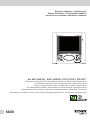 1
1
-
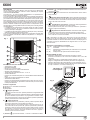 2
2
-
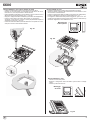 3
3
-
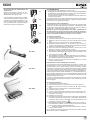 4
4
-
 5
5
-
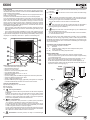 6
6
-
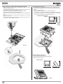 7
7
-
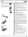 8
8
-
 9
9
-
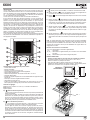 10
10
-
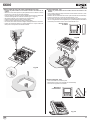 11
11
-
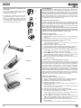 12
12
-
 13
13
-
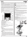 14
14
-
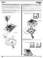 15
15
-
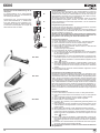 16
16
-
 17
17
-
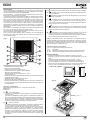 18
18
-
 19
19
-
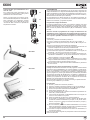 20
20
-
 21
21
-
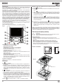 22
22
-
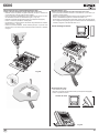 23
23
-
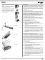 24
24
-
 25
25
-
 26
26
-
 27
27
-
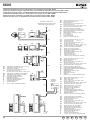 28
28
-
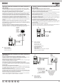 29
29
-
 30
30
-
 31
31
-
 32
32


Elvox 6721 Guida d'installazione
- Tipo
- Guida d'installazione
- Questo manuale è adatto anche per
in altre lingue
- English: Elvox 6721 Installation guide
- français: Elvox 6721 Guide d'installation
- español: Elvox 6721 Guía de instalación
- Deutsch: Elvox 6721 Installationsanleitung
- português: Elvox 6721 Guia de instalação
Documenti correlati
-
Elvox 6611 Istruzioni per l'uso
-
-
Elvox 7200 Series Istruzioni per l'uso
-
-
-
-
-
-
-
Altri documenti
-
Panasonic VLSVN511EX Istruzioni per l'uso
-
-
-
Bticino 306905 Istruzioni per l'uso
-
-
CAME 840XC-0010 Guida d'installazione
-
Vimar 41002 Manuale utente
-
-
 Thomashilfen Grip rail, grey Assembly Instructions
-
