Asus TUF GAMING B650-PLUS WIFI Manuale utente
- Categoria
- Schede madri
- Tipo
- Manuale utente

Motherboard
TUF GAMING
B650-PLUS WIFI

ii
E21902
Revised Edition V3
April 2023
Copyright © 2023 ASUSTeK COMPUTER INC. All Rights Reserved.
No part of this manual, including the products and software described in it, may be reproduced,
transmitted, transcribed, stored in a retrieval system, or translated into any language in any form or by any
means, except documentation kept by the purchaser for backup purposes, without the express written
permission of ASUSTeK COMPUTER INC. (“ASUS”).
Product warranty or service will not be extended if: (1) the product is repaired, modified or altered, unless
such repair, modification of alteration is authorized in writing by ASUS; or (2) the serial number of the
product is defaced or missing.
ASUS PROVIDES THIS MANUAL “AS IS” WITHOUT WARRANTY OF ANY KIND, EITHER EXPRESS
OR IMPLIED, INCLUDING BUT NOT LIMITED TO THE IMPLIED WARRANTIES OR CONDITIONS OF
MERCHANTABILITY OR FITNESS FOR A PARTICULAR PURPOSE. IN NO EVENT SHALL ASUS, ITS
DIRECTORS, OFFICERS, EMPLOYEES OR AGENTS BE LIABLE FOR ANY INDIRECT, SPECIAL,
INCIDENTAL, OR CONSEQUENTIAL DAMAGES (INCLUDING DAMAGES FOR LOSS OF PROFITS,
LOSS OF BUSINESS, LOSS OF USE OR DATA, INTERRUPTION OF BUSINESS AND THE LIKE),
EVEN IF ASUS HAS BEEN ADVISED OF THE POSSIBILITY OF SUCH DAMAGES ARISING FROM ANY
DEFECT OR ERROR IN THIS MANUAL OR PRODUCT.
SPECIFICATIONS AND INFORMATION CONTAINED IN THIS MANUAL ARE FURNISHED FOR
INFORMATIONAL USE ONLY, AND ARE SUBJECT TO CHANGE AT ANY TIME WITHOUT NOTICE,
AND SHOULD NOT BE CONSTRUED AS A COMMITMENT BY ASUS. ASUS ASSUMES NO
RESPONSIBILITY OR LIABILITY FOR ANY ERRORS OR INACCURACIES THAT MAY APPEAR IN THIS
MANUAL, INCLUDING THE PRODUCTS AND SOFTWARE DESCRIBED IN IT.
Products and corporate names appearing in this manual may or may not be registered trademarks or
copyrights of their respective companies, and are used only for identification or explanation and to the
owners’ benefit, without intent to infringe.

iii
Contents
Safety information ...................................................................................................... iv
About this guide .......................................................................................................... v
Package contents ....................................................................................................... vi
TUF GAMING B650-PLUS WIFI specifications summary........................................ vi
Chapter 1: Product Introduction
1.1 Before you proceed ...................................................................................... 1-1
1.2 Motherboard overview ................................................................................. 1-2
1.3 Central Processing Unit (CPU) .................................................................. 1-10
1.4 System memory .......................................................................................... 1-12
1.5 M.2 installation ............................................................................................ 1-14
1.6 Wi-Fi moving antenna installation ............................................................ 1-16
Chapter 2: BIOS and RAID Support
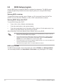
2.1 Knowing BIOS ............................................................................................... 2-1
2.2 BIOS Setup program .................................................................................... 2-2
2.3 ASUS EZ Flash 3 ........................................................................................... 2-3
2.4 ASUS CrashFree BIOS 3 .............................................................................. 2-4
2.5 RAID configurations ..................................................................................... 2-5
Appendix
Notices ..................................................................................................................... A-1
ASUS contact information .................................................................................... A-11
Service and Support ............................................................................................. A-11

iv
Button/Coin Batteries Safety Information
WARNING
KEEP OUT OF REACH OF CHILDREN
Swallowing can lead to chemical burns,
perforation of soft tissue, and death. Severe
burns can occur within 2 hours of ingestion.
Seek medical attention immediately.
Safety information
Electrical safety
• To prevent electrical shock hazard, disconnect the power cable from the electrical
outlet before relocating the system.
• When adding or removing devices to or from the system, ensure that the power cables
for the devices are unplugged before the signal cables are connected. If possible,
disconnect all power cables from the existing system before you add a device.
• Before connecting or removing signal cables from the motherboard, ensure that all
power cables are unplugged.
• Seek professional assistance before using an adapter or extension cord. These
devices could interrupt the grounding circuit.
• Ensure that your power supply is set to the correct voltage in your area. If you are not
sure about the voltage of the electrical outlet you are using, contact your local power
company.
• If the power supply is broken, do not try to fix it by yourself. Contact a qualified service
technician or your retailer.
Operation safety
• Before installing the motherboard and adding devices on it, carefully read all the
manuals that came with the package.
• Before using the product, ensure all cables are correctly connected and the power
cables are not damaged. If you detect any damage, contact your dealer immediately.
• To avoid short circuits, keep paper clips, screws, and staples away from connectors,
slots, sockets and circuitry.
• Avoid dust, humidity, and temperature extremes. Do not place the product in any area
where it may become wet.
• Place the product on a stable surface.
• If you encounter technical problems with the product, contact a qualified service
technician or your retailer.
• Your motherboard should only be used in environments with ambient temperatures
between 0°C and 40°C.

v
About this guide
This user guide contains the information you need when installing and configuring the
motherboard.
How this guide is organized
This guide contains the following parts:
• Chapter 1: Product Introduction
This chapter describes the features of the motherboard and the new technology it
supports. It includes descriptions of the switches, jumpers, and connectors on the
motherboard.
• Chapter 2: BIOS and RAID Support
This chapter tells how to boot into the BIOS, upgrade BIOS using the EZ Flash Utility
and support on RAID.
Where to find more information
Refer to the following sources for additional information and for product and software
updates.
1. ASUS website
The ASUS website (www.asus.com) provides updated information on ASUS hardware
and software products.
2. Optional documentation
Your product package may include optional documentation, such as warranty flyers,
that may have been added by your dealer. These documents are not part of the
standard package.
Conventions used in this guide
To ensure that you perform certain tasks properly, take note of the following symbols used
throughout this user guide.
CAUTION: Information to prevent damage to the components and injuries to
yourself when trying to complete a task.
IMPORTANT: Instructions that you MUST follow to complete a task.
NOTE: Tips and additional information to help you complete a task.

vi
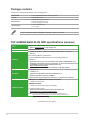
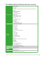
TUF GAMING B650-PLUS WIFI specifications summary
CPU AMD Socket AM5 for AMD Ryzen™ 7000 Series Desktop Processors*
* Refer to www.asus.com for CPU support list.
Chipset AMD B650 Chipset
Memory
4 x DIMM slots, Max. 128GB, DDR5 ECC and Non-ECC, Un-buffered
Memory*
Dual Channel Memory Architecture
Supports AMD EXTended Profiles for Overclocking (EXPO™)
OptiMem II
* Supported memory types, data rate (speed), and number of DRAM modules vary
depending on the CPU and memory configuration, for more information please refer
to CPU/Memory Support under the Support tab or visit
https://www.asus.com/support/.
** Non-ECC, Un-buffered DDR5 Memory supports On-Die ECC function.
Graphics
1 x DisplayPort*
1 x HDMI™ port**
* Supports max. 8K@60Hz as specified in DisplayPort 1.4.
** Supports 4K@60Hz as specified in HDMI 2.1.
*** VGA resolution support depends on processors’ or graphic cards’ resolution.
Expansion Slots
AMD Ryzen™ 7000 Series Desktop Processors*
1 x PCIe 4.0/3.0 x16 slot
AMD B650 Chipset
1 x PCIe 4.0/3.0 x16 slot (supports x4 mode)
2 x PCIe 4.0/3.0 x1 slots
* Please check the PCIe bifurcation table on the support site
(https://www.asus.com/support/FAQ/1037507/).
Note: To ensure compatibility of the device installed, please refer to
https://www.asus.com/support/ for the list of supported peripherals.
(continued on the next page)
Package contents
Check your motherboard package for the following items.
Motherboard 1 x TUF GAMING B650-PLUS WIFI motherboard
Cables 2 x SATA 6Gb/s cables
Miscellaneous
1 x ASUS Wi-Fi moving antennas
2 x Rubber Package(s) for M.2
1 x Screw package for M.2 SSD
Documentation 1 x TUF Certification card
1 x User guide
If any of the above items is damaged or missing, contact your retailer.

vii
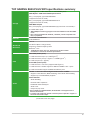
TUF GAMING B650-PLUS WIFI specifications summary
Storage
Total supports 3 x M.2 slots and 4 x SATA 6Gb/s ports*
AMD Ryzen™ 7000 Series Desktop Processors
M.2_1 slot (Key M), type 2242/2260/2280
(supports PCIe 5.0 x4 mode)
M.2_2 slot (Key M), type 2242/2260/2280/22110
(supports PCIe 4.0 x4 mode)
AMD B650 Chipset
M.2_3 slot (Key M), type 2242/2260/2280 (supports PCIe 4.0 x4 mode)**
4 x SATA 6Gb/s ports
* AMD RAIDXpert2 Technology supports both PCIe RAID 0/1/10 and SATA RAID
0/1/10.
** M.2_3 shares bandwidth with PCIEX16_2. PCIEX16_2 will be suspended once
M.2_3 is populated.
Ethernet 1 x Realtek 2.5Gb Ethernet
TUF LANGuard
Wireless &
Bluetooth®
Wi-Fi 6
2x2 Wi-Fi 6 (802.11 a/b/g/n/ac/ax)
Supports 2.4/5GHz frequency band
Bluetooth® v5.2*
* The Bluetooth version may vary, please refer to the Wi-Fi module
manufacturer’s website for the latest specifications.
USB
Rear USB (Total 8 ports)
1 x USB 3.2 Gen 2x2 port (1 x USB Type-C®)
3 x USB 3.2 Gen 2 ports (2 x Type-A +1 x USB Type-C® )
4 x USB 2.0 ports (4 x Type-A)
Front USB (Total 7 ports)
1 x USB 3.2 Gen 1 connector (supports USB Type-C®)
1 x USB 3.2 Gen 1 header supports 2 additional USB 3.2 Gen 1 ports
2 x USB 2.0 headers support 4 additional USB 2.0 ports
Audio
Realtek 7.1 Surround Sound High Definition Audio CODEC*
- Supports: Jack detection, Multi-streaming, Front Panel Jack-retasking
- Supports up to 24-Bit/192kHz playback
Audio Features
- Audio Shielding
- Premium audio capacitors
- Dedicated audio PCB layers
- Audio cover
- Unique de-pop circuit
* Due to limitations in HDA bandwidth, 32-Bit/192 kHz is not supported for 7.1
Surround Sound audio.
** A chassis with an HD audio module in the front panel is required to support 7.1
Surround Sound audio output.
(continued on the next page)

viii
TUF GAMING B650-PLUS WIFI specifications summary
Back Panel I/O
Ports
1 x USB 3.2 Gen 2x2 port (1 x USB Type-C®)
3 x USB 3.2 Gen 2 ports (2 x Type-A + 1 x USB Type-C®)
4 x USB 2.0 ports (2 x Type-A)
1 x DisplayPort
1 x HDMI™ port
1 x Wi-Fi Module
1 x Realtek 2.5Gb Ethernet port
5 x Audio jacks
1 x BIOS FlashBack™ button
Internal I/O
Connectors
Fan and cooling related
1 x 4-pin CPU Fan header
1 x 4-pin CPU OPT Fan header
1 x 4-pin AIO Pump header
4 x 4-pin Chassis Fan headers
Power related
1 x 24-pin Main Power connector
1 x 8-pin +12V Power connector
1 x 4-pin +12V Power connector
Storage related
3 x M.2 slots (Key M)
4 x SATA 6Gb/s ports
USB
1 x USB 3.2 Gen 1 connector (supports USB Type-C®)
1 x USB 3.2 Gen 1 header supports 2 additional USB 3.2 Gen 1 ports
2 x USB 2.0 headers support 4 additional USB 2.0 ports
Miscellaneous
3 x Addressable Gen 2 headers
1 x Aura RGB header
1 x Clear CMOS header
1 x COM Port header
1 x Front Panel Audio header (AAFP)
1 x 20-3 pin System Panel header with Chassis intrude function
1 x Thunderbolt™ (USB4®) header
Special Features
ASUS TUF PROTECTION
- DIGI+ VRM (- Digital power design with DrMOS)
- Enhanced DRAM Overcurrent Protection
- ESD Guards
- TUF LANGuard
- Overvoltage Protection
- SafeSlot+
- Stainless-Steel Back I/O
(continued on the next page)

ix
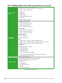
TUF GAMING B650-PLUS WIFI specifications summary
Special Features
ASUS Q-Design
- M.2 Q-Latch
- Q-DIMM
- Q-LED (CPU [red], DRAM [yellow], VGA [white], Boot Device [yellow green])
- Q-Slot
ASUS Thermal Solution
- M.2 heatsink
- VRM heatsink design
ASUS EZ DIY
- BIOS FlashBack™ button
- BIOS FlashBack™ LED
- ProCool
- Pre-mounted I/O shield
- SafeDIMM
Aura Sync
- Aura RGB header
- Addressable Gen 2 headers
Software
Features
ASUS Exclusive Software
Armoury Crate
- Aura Creator
- Aura Sync
- Fan Xpert 4
- Power Saving
- Two-Way AI Noise Cancelation
AI Suite 3
- TurboV EVO
- DIGI+ VRM
- PC Cleaner
TUF GAMING CPU-Z
DTS Audio Processing
MyASUS
Norton Anti-virus software (Free Trial version)
WinRAR
UEFI BIOS
ASUS EZ DIY
- ASUS CrashFree BIOS 3
- ASUS EZ Flash 3
- ASUS UEFI BIOS EZ Mode
BIOS 256 Mb Flash ROM, UEFI AMI BIOS
Manageability WOL by PME, PXE
Operating
System
Windows® 11
Windows® 10 64-bit
Form Factor ATX Form Factor
12 inch x 9.6 inch (30.5 cm x 24.4 cm)

x
• Specifications are subject to change without notice. Please refer to the ASUS website
for the latest specifications.
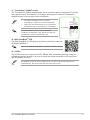
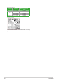
• MyASUS offers a variety of support features such as helping to troubleshoot issues,
optimizing product performance, integrating ASUS software, and recovery drive
creation. Please scan the code for installation guide and FAQ.
• For more information on downloading and installing drivers and utilities for your
motherboard, please scan the code below:

1-1
1
TUF GAMING B650-PLUS WIFI
Product Introduction
1.1 Before you proceed
Take note of the following precautions before you install motherboard components or change
any motherboard settings.
• Unplug the power cord from the wall socket before touching any component.
• Before handling components, use a grounded wrist strap or touch a safely grounded
object or a metal object, such as the power supply case, to avoid damaging them due
to static electricity.
• Hold components by the edges to avoid touching the ICs on them.
• Whenever you uninstall any component, place it on a grounded antistatic pad or in the
bag that came with the component.
• Before you install or remove any component, ensure that the ATX power supply is
switched off or the power cord is detached from the power supply. Failure to do so
may cause severe damage to the motherboard, peripherals, or components.
• The pin definitions in this chapter are for reference only. The pin names depend on the
location of the header/jumper/connector.
• For more information on installing your motherboard, please scan the code below:

1-2 Chapter 1: Product Introduction
Unplug the power cord before installing or removing the motherboard. Failure to do so can
cause you physical injury and damage motherboard components.
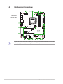
1.2 Motherboard overview
Place this
side towards
the rear of the
chassis
DDR5 DIMM_A1 (64bit, 288-pin module)
DDR5 DIMM_A2 (64bit, 288-pin module)
DDR5 DIMM_B1 (64bit, 288-pin module)
DDR5 DIMM_B2 (64bit, 288-pin module)
AIO_PUMP
CPU_OPT
CPU_FAN
CHA_FAN3
CLRTC
COM
M.2_3(SOCKET3)
M.2_2(SOCKET3)
M.2_1(SOCKET3)
PANEL
AAFP
COM_DEBUG
SATA6G_1SATA6G_2SATA6G_3SATA6G_4
ATX_PWR
U32G1_89
CHA_FAN2
CHA_FAN4
CHA_FAN1
AUDIO
Super
I/O
PCIEX1_1
PCIEX1_2
2280 2260 2242
2260 2280
22422260228022110 2242
PCIEX16_1
PCIEX16_2
USB_1415 USB_1617
RGB_HEADER
ADD_GEN 2_3
U32G2_3
LAN_U32G2_4
USB_1_5_1213
U32G2_C2
U32G2X2_C6
M.2(WIFI)
HDMI_DP
BIOS_FLBK
FLBK_LED
DIGI
+VRM
24.4cm(9.6in)
30.5cm(12in)
BATTERY
U32_C10
ATX_12V_2 ATX_12V_1
TB_HEADER
AMD
B650
X
PCIE SATA
4.0 X4
M.2_3(SOCKET3)
X
PCIE SATA
4.0 X4
M.2_2(SOCKET3)
PCIE SATA
5.0 X4 X
M.2_1(SOCKET3)
Ethernet
ADD_GEN 2_2
CPU
DRAM
VGA
BOOT
ADD_GEN 2_1
1st
SOCKET AM5
8
4
9
5
7
6
6
131415
4
18
3
5
2
4 111
16101112 17 44
19

1-3
1.2.1 Layout contents
1. CPU socket
The motherboard comes with a Socket AM5 designed for AMD Ryzen™ 7000 Series
Desktop Processors.
For more details, refer to Central Processing Unit (CPU).
2. DDR5 DIMM slots
The motherboard comes with Dual Inline Memory Modules (DIMM) slots designed for DDR5
(Double Data Rate 5) memory modules.
For more details, refer to System memory.
3. Expansion slots
This motherboard supports two PCIe x16 graphics cards and two PCIe x1 network cards,
SCSI cards and other cards that comply with the PCI Express specification.
• Additional PCIe bifurcation and M.2 settings for RAID function are also supported
when a Hyper M.2 x16 series card is installed.
• For full details on the PCIe bifurcation, you may visit the support site at
https://www.asus.com/support/FAQ/1037507/.
• The Hyper M.2 x16 series card is sold separately.
• Adjust the PCIe bifurcation under BIOS settings.
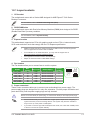
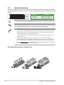
4. Fan headers
The Fan headers allow you to connect fans to cool the system.
Header Max.
Current Max. Power Default Speed Shared
Control
CPU_FAN 1A 12W Q-Fan Controlled A
CPU_OPT 1A 12W Q-Fan Controlled A
CHA_FAN1 1A 12W Q-Fan Controlled -
CHA_FAN2 1A 12W Q-Fan Controlled -
CHA_FAN3 1A 12W Q-Fan Controlled -
CHA_FAN4 1A 12W Q-Fan Controlled -
AIO_PUMP 1A 12W Full-Speed -
5. Power connectors
These Power connectors allow you to connect your motherboard to a power supply. The
power supply plugs are designed to fit in only one orientation. Find the proper orientation and
push down firmly until the power supply plugs are fully inserted.
Ensure to connect the 8-pin power plug, or connect both the 8-pin and 4-pin power plugs.
• We recommend that you use a PSU with a higher power output when configuring a
system with more power-consuming devices. The system may become unstable or
may not boot up if the power is inadequate.
• If you want to use two high-end PCI Express x16 cards, use a PSU with 1000W power
or above to ensure the system stability.
FAN PWM
FAN IN
FAN PWR
GND
GND
FAN PWR
FAN IN
FAN PWM
TUF GAMING B650-PLUS WIFI

1-4
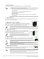
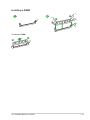
6. M.2 slots (Key M)
The M.2 slots allow you to install M.2 devices such as M.2 SSD modules.
• AMD Ryzen™ 7000 Series Desktop Processors:
- M.2_1 slot supports PCIe 5.0 x4 mode M Key design and type 2242/2260/2280
storage devices.
- M.2_2 slot supports PCIe 4.0 x4 mode M key design and type
2242/2260/2280/22110 storage devices.
• AMD B650 Chipset:
- M.2_3 slot supports PCIe 4.0 x4 mode M key design and type 2242/2260/2280
storage devices.
7. SATA 6Gb/s ports
The SATA 6Gb/s ports allow you to connect SATA devices such as optical disc drives and
hard disk drives via SATA cables.
8. USB 3.2 Gen 1 Type-C® connector
The USB 3.2 Gen 1 connector (USB Type-C®) allows you to connect a
USB 3.2 Gen 1 module for an additional USB 3.2 Gen 1 Type-C® port.
The connector provides a data transfer speed of up to 5 Gb/s.
The USB 3.2 Gen 1 Type-C® module is purchased separately.
9. USB 3.2 Gen 1 header
The USB 3.2 Gen 1 header allows you to connect a USB 3.2 Gen
1 module for additional USB 3.2 Gen 1 ports. The USB 3.2 Gen 1
header provides data transfer speeds of up to 5 Gb/s.
The USB 3.2 Gen 1 module is purchased separately.
10. USB 2.0 headers
The USB 2.0 headers allow you to connect a USB module for additional USB
2.0 ports. The USB 2.0 headers provide data transfer speeds of up to 480 Mb/s.
DO NOT connect a 1394 cable to the USB connectors. Doing so will
damage the motherboard!
The USB 2.0 module is purchased separately.
11. Addressable Gen 2 headers
The Addressable Gen 2 headers allow you to connect individually addressable
RGB WS2812B LED strips or WS2812B based LED strips.
The Addressable Gen 2 headers support WS2812B addressable RGB LED strips (5V/Data/
Ground), with a maximum power rating of 3A (5V), and the addressable headers on this
board can handle a combined maximum of 500 LEDs.
SBU2
SBU1
CC1
VBUS
RX1-
RX1+
GND
TX1-
TX1+
VBUS
VBUS
TX2+
TX2-
GND
RX2+
RX2-
GND
D-
D+
CC2
USB3+5V
IntA_P1_SSRX-
IntA_P1_SSRX+
GND
IntA_P1_SSTX-
IntA_P1_SSTX+
GND
IntA_P1_D-
IntA_P1_D+
GND
PIN 1
USB3+5V
IntA_P2_SSRX-
IntA_P2_SSRX+
GND
IntA_P2_SSTX-
IntA_P2_SSTX+
GND
IntA_P2_D-
IntA_P2_D+
USB+5V
USB_E1-
USB_E1+
GND
NC
USB+5V
USB_E2-
USB_E2+
GND
PIN 1
ADD_GEN 2
+5V
Data
Ground
PIN 1
Chapter 1: Product Introduction

1-5
Before you install or remove any component, ensure that the power supply is switched off
or the power cord is detached from the power supply. Failure to do so may cause severe
damage to the motherboard, peripherals, or components.
• Actual lighting and color will vary with LED strip.
• If your LED strip does not light up, check if the addressable RGB LED strip is
connected in the correct orientation, and the 5V connector is aligned with the 5V
header on the motherboard.
• The addressable RGB LED strip will only light up when the system is powered on.
• The addressable RGB LED strip is purchased separately.
12. Aura RGB header
The RGB header allows you to connect RGB LED strips.
The RGB headers support 5050 RGB multi-color LED strips (12V/G/R/B), with a maximum
power rating of 3A (12V), and no longer than 3m.
Before you install or remove any component, ensure that the ATX power supply is switched
off or the power cord is detached from the power supply. Failure to do so may cause severe
damage to the motherboard, peripherals, or components.
• Actual lighting and color will vary with LED strip.
• If your LED strip does not light up, check if the RGB LED extension cable and the
RGB LED strip are connected in the correct orientation, and the 12V connector is
aligned with the 12V header on the motherboard.
• The LED strip will only light up when the system is powered on.
• The LED strip is purchased separately.
13. Clear CMOS header
The Clear CMOS header allows you to clear the Real Time Clock (RTC) RAM in
the CMOS, which contains the date, time, system passwords, and system setup
parameters.
To erase the RTC RAM:
1. Turn OFF the computer and unplug the power cord.
2. Short-circuit pin 1-2 with a metal object or jumper cap for about 5-10 seconds.
3. Plug the power cord and turn ON the computer.
4. Hold down the <Del> key during the boot process and enter BIOS setup to
re-enter data.
DO NOT short-circuit the pins except when clearing the RTC RAM. Short-circuiting or
placing a jumper cap will cause system boot failure!
If the steps above do not help, remove the onboard button cell battery and short the two
pins again to clear the CMOS RTC RAM data. After clearing the CMOS, reinstall the button
cell battery.
CLRTC
+3V_BAT
GND
PIN 1
TUF GAMING B650-PLUS WIFI

1-6
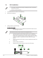
14. COM Port header
The COM (Serial) Port header allows you to connect a COM port module.
Connect the COM port module cable to this header, then install the module to a
slot opening on the system chassis.
15. Front panel audio header
This header is for a chassis-mounted front panel audio I/O module that
supports HD Audio. Connect one end of the front panel audio I/O module
cable to this header.
We recommend that you connect a high-definition front panel audio
module to this header to avail of the motherboard’s high-definition
audio capability.
16. System Panel header
This header supports several chassis-mounted functions.
• System Power LED header (PLED)
The 2-pin and/or 3-1 pin headers allow you to connect the
System Power LED. The System Power LED lights up when
the system is connected to a power source, or when you
turn on the system power, and blinks when the system is in
sleep mode.
• Storage Device Activity LED header (HDD_LED)
The 2-pin header allows you to connect the Storage Device
Activity LED. The Storage Device Activity LED lights up or
blinks when data is read from or written to the storage device or storage device add-on
card.
• System Warning Speaker header (SPEAKER)
The 4-pin header allows you to connect the chassis-mounted system warning speaker.
The speaker allows you to hear system beeps and warnings.
• Power Button/Soft-off Button header (PWRSW)
The 3-1 pin header allows you to connect the system power button. Press the
power button to power up the system, or put the system into sleep or soft-off mode
(depending on the operating system settings).
• Reset button header (RESET)
The 2-pin header allows you to connect the chassis-mounted reset button. Press the
reset button to reboot the system.
• Chassis intrusion header (CHASSIS)
The 2-pin header allows you to connect the chassis-mounted intrusion detection
sensor or switch. The chassis intrusion sensor or switch sends a high-level signal to
the header when a chassis component
COM
PIN 1
DCD
TXD
GND
RTS
RI
RXD
DTR
DSR
CTS
AAFP
AGND
NC
SENSE1_RETUR
SENSE2_RETUR
PORT1 L
PORT1 R
PORT2 R
SENSE_SEND
PORT2 L
HD-audio-compliant
pin definition
Chapter 1: Product Introduction

1-7
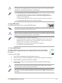
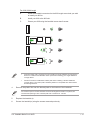
17. Thunderbolt™ (USB4®) header
The Thunderbolt™ (USB4®) header allows you to connect an add-on Thunderbolt™ I/O card
that supports Intel®’s Thunderbolt™ Technology, allowing you to connect Thunderbolt™-
enabled devices to form a daisy chain-configuration.
• The add-on Thunderbolt™ I/O card and
Thunderbolt™ cables are purchased separately.
• Please visit the official website of your purchased
Thunderbolt card for more details on compatibility.
The Thunderbolt™ card can only be used when
installed to the PCIEX16_2 slot. Ensure to install your
Thunderbolt™ card to the PCIEX16_2 slot.
18. BIOS FlashBackTM LED
The BIOS FlashBack™ LED lights up or blinks to indicate the status of
the BIOS FlashBack™.
Scan the code for more information on BIOS FlashBackTM function.
19. Q-LEDs
The Q-LEDs check key components (CPU, DRAM, VGA, and booting devices) during the
motherboard booting process. If an error is found, the critical component’s LED stays lit up
until the problem is solved.
The Q-LEDs provide the most probable cause of an error code as a starting point for
troubleshooting. The actual cause may vary from case to case.
PIN 1
FORCE_PWR
CIO_PLUG_EVENT
SLP_S3#
SLP_S5#
GND
RTD3_SW
I2C_SCL
I2C_SDA
I2C_IRQ#
RTD3_POWER_EN
S_SLP_S0#_IDLE
PERST_N
WAKE#
TB_HEADER
TUF GAMING B650-PLUS WIFI

1-8
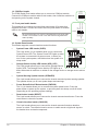
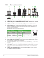
1.2.2 Rear panel connectors
1. DisplayPort. This port is for a DisplayPort-compatible device.
2. USB 3.2 Gen 2 (up to 10Gbps) ports (teal blue, Type A). These Universal Serial Bus
3.2 (USB 3.2) ports are for USB 3.2 Gen 2 devices.
3. USB 2.0 ports. These Universal Serial Bus (USB) ports are for USB 2.0 devices.
8 9 11
1 2 3 4
102
5 6 7
12 13 14
Realtek 2.5Gb Ethernet port LED indications
Speed LED
Status Description
OFF No link
GREEN 2.5 Gbps connection
ORANGE 1 Gbps / 100 Mbps /
10 Mbps connection
Activity Link LED
Status Description
OFF No link
GREEN Linked
BLINKING Data activity
ACT/LINK
LED
SPEED
LED
Ethernet port
5. Center / Subwoofer port (orange). This port connects the center/subwoofer speakers.
6. Rear Speaker Out port (black). This port connects the rear speakers in a 4 channel,
5.1 channel, or 7.1 channel audio configuration.
7. Line In port (light blue). This port connects the tape, CD, DVD player, or other audio
sources.
8. HDMI™ port. This port is for a High-Definition Multimedia Interface (HDMI™) connector,
and is HDCP compliant allowing playback of HD DVD, Blu-ray, and other protected
content.
9. USB 3.2 Gen 2 port (USB Type-C®). This Universal Serial Bus 3.2 (USB 3.2) port is
for a USB 3.2 Gen 2 Type-C® device.
4. 2.5Gb Ethernet port. This port allows 2.5Gbps Ethernet connection to a Local Area
Network (LAN) through a network hub. Refer to the table one the next page for the
Ethernet port LED indications.
Chapter 1: Product Introduction

1-9
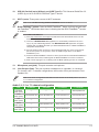
Audio 2, 4, 5.1 or 7.1-channel configuration
Port 2-channel 4-channel 5.1-channel 7.1-channel
Light Blue
(Rear panel) — — — Side Speaker Out
Lime
(Rear panel) Front Speaker Out Front Speaker Out Front Speaker Out Front Speaker Out
Pink
(Rear panel) — — — —
Black
(Rear panel) — Rear Speaker Out Rear Speaker Out Rear Speaker Out
Orange
(Rear panel) — — Center/Subwoofer Center/Subwoofer
13. Microphone port (pink). This port connects a microphone.
14. Line Out port (lime). This port connects a headphone or a speaker. In 4-channel,
5.1-channel, and 7.1-channel configurations, the function of this port becomes Front
Speaker Out.
Refer to the audio configuration table below for the function of the audio ports in 2, 4, 5.1,
or 7.1-channel configuration.
11. Wi-Fi 6 ports. These ports connect to Wi-Fi antennas.
Refer to the 1.6 Wi-Fi moving antenna installation section for details.
12. BIOS Flashback™ button. Press the BIOS FlashBackTM button for three seconds until
the FlashBackTM LED blinks three times, indicating that the BIOS FlashBackTM function
is enabled.
To use BIOS FlashBack™:
1) Visit https://www.asus.com/support/ and download the latest BIOS version for this
motherboard.
2) Launch the BIOSRenamer.exe application to automatically rename the file, then
copy it to your USB storage device. The BIOSRenamer.exe application is zipped
together with your BIOS file when you download a BIOS file for a BIOS FlashBack™
compatible motherboard.
3) Plug the 24-pin power connector to the motherboard and turn on the power supply
(No need to power on the system). Insert the USB storage device to the BIOS
FlashBack™ port.
4) Press the BIOS FlashBack™ button for three (3) seconds until the BIOS FlashBack™
LED blinks three times, indicating that the BIOS FlashBack™ function is enabled.
5) Wait until the light goes out, indicating that the BIOS updating process is completed.
10. USB 3.2 Gen 2x2 (up to 20Gbps) port (USB Type-C®). This Universal Serial Bus 3.2
(USB 3.2) port is for a USB 3.2 Gen 2x2 Type-C® device.
TUF GAMING B650-PLUS WIFI

1-10
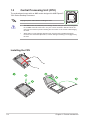
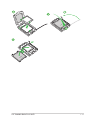
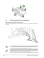
Installing the CPU
1.3 Central Processing Unit (CPU)
The motherboard comes with an AM5 socket designed for AMD Ryzen™
7000 Series Desktop Processors.
Unplug all power cables before installing the CPU.
• The AM5 socket has a different pinout design. Ensure that you use a CPU designed
for the AM5 socket.The CPU fits in only one correct orientation. DO NOT force the
CPU into the socket to prevent bending the connectors on the socket and damaging
the CPU.
• ASUS will not cover damages resulting from incorrect CPU installation/removal,
incorrect CPU orientation/placement, or other damages resulting from negligence by
the user.
Chapter 1: Product Introduction
La pagina si sta caricando...
La pagina si sta caricando...
La pagina si sta caricando...
La pagina si sta caricando...
La pagina si sta caricando...
La pagina si sta caricando...
La pagina si sta caricando...
La pagina si sta caricando...
La pagina si sta caricando...
La pagina si sta caricando...
La pagina si sta caricando...
La pagina si sta caricando...
La pagina si sta caricando...
La pagina si sta caricando...
La pagina si sta caricando...
La pagina si sta caricando...
La pagina si sta caricando...
La pagina si sta caricando...
La pagina si sta caricando...
La pagina si sta caricando...
La pagina si sta caricando...
La pagina si sta caricando...
La pagina si sta caricando...
-
 1
1
-
 2
2
-
 3
3
-
 4
4
-
 5
5
-
 6
6
-
 7
7
-
 8
8
-
 9
9
-
 10
10
-
 11
11
-
 12
12
-
 13
13
-
 14
14
-
 15
15
-
 16
16
-
 17
17
-
 18
18
-
 19
19
-
 20
20
-
 21
21
-
 22
22
-
 23
23
-
 24
24
-
 25
25
-
 26
26
-
 27
27
-
 28
28
-
 29
29
-
 30
30
-
 31
31
-
 32
32
-
 33
33
-
 34
34
-
 35
35
-
 36
36
-
 37
37
-
 38
38
-
 39
39
-
 40
40
-
 41
41
-
 42
42
-
 43
43


Asus TUF GAMING B650-PLUS WIFI Manuale utente
- Categoria
- Schede madri
- Tipo
- Manuale utente