SICK SENSICK V12(T)-2 Istruzioni per l'uso
- Tipo
- Istruzioni per l'uso

Änderungen vorbehalten
Angegebene Produkteigenschaften und technische Daten stellen keine
Garantieerklärung dar
1202 GO
V 12(T)-2...
DEUTSCH
Lichtschrankenfamilie
Betriebsanleitung
Sicherheitshinweise
‡ Vor der Inbetriebnahme die Betriebsanleitung lesen.
‡ Anschluss, Montage und Einstellung nur durch Fachpersonal.
‡ Gerät bei Inbetriebnahme vor Feuchte und Verunreinigung schützen.
‡ Kein Sicherheitsbauteil gemäß EU-Maschinenrichtlinie.
Bestimmungsgemäße Verwendung
Die Lichtschranken V 12(T)-2... sind optoelektronische Sensoren und wer-
den zum optischen, berührungslosen Erfassen von Sachen, Tieren und Per-
sonen eingesetzt.
Inbetriebnahme
V 12(T)-2, Reflexions-Lichttaster energetisch:
Sensor montieren, kontaktieren und auf Tastobjekt ausrichten.
Empfindlichkeitseinstellung:
Sie haben zwei Optionen für die Empfindlichkeitseinstellung zur Verfügung:
– manuell per Teach-in-Taste und
– elektronisch, extern über Controll-Eingang C.
Einfachste Programmierung: Teach-in-Taste 1 x drücken oder Controll-Ein-
gang C (0 V) 1 x aktivieren: Empfindlichkeitseinstellung ist beendet.
Feedback: Anzeige-LED gelb. Dauerhafte Speicherung der „eingelernten
Schaltschwelle und Hysterese“, auch bei beliebig langer Spannungs-
unterbrechung.
Tastobjekt immer im Lichtweg in der Sollposition positionieren.
Zwei Teach-in-Modi stehen für Ihre optimal angepasste Empfindlichkeits-
Einstellung zur Verfügung:
Mode 1; große Funktionsreserve; Applikationen:
Standard-Empfindlichkeit; empfohlen für alle Standard-Applikationen.
Funktionsreserve Faktor > 2 über Schaltschwelle; kurze „Teach-in-Zeit“
(> 2 s ... < 7 s).
Teach-in-Taste drücken oder Controll-Eingang C (0 V) aktivieren
(> 2 s ...< 7 s): Anzeige-LED gelb – erlischt – leuchtet nach > 2 s wieder
auf – Teach-in-Signal deaktivieren. Empfindlichkeits-Einstellung beendet.
Anzeige-LED gelb leuchtet nach abgeschlossenem Teach-in-Prozess in
Mode 1.
A) Applikation überprüfen:
Tastobjekt entfernen. Die gelbe LED erlischt? OK. Gelbe LED leuchtet
(Hintergrundeinfluss?): hohe Empfindlichkeit einstellen, siehe Mode 2.
Mode 2; exakter Schaltpunkt, hohe Empfindlichkeit; Applikationen:
geeignet für geringe Unterschiede Tastobjekt/Hintergrund, für
Positionieraufgaben, für einfache Kontrast-Erkennung.
Kleine Schalthysterese und geringere Funktionsreserve, Faktor > 1 < 2
über Schaltschwelle; lange „Teach-in-Zeit“ (> 8 s).
Teach-in-Taste drücken oder Controll-Eingang C (0 V) aktivieren (> 8 s): An-
zeige-LED gelb – erlischt – leuchtet nach > 2 s wieder auf – blinkt nach
> 8 s – Teach-in-Signal deaktivieren – Empfindlichkeits-Einstellung
beendet! Anzeige-LED gelb blinkt permanent nach abgeschlossenem
Teach-in-Prozess in Mode 2.
Applikation überprüfen: siehe A).
VL 12-2...; Reflexions-Lichtschranke mit Polarisationsfilter, Rotlicht
Durch den integrierten Polarisationsfilter können Objekte mit glänzender
Oberfläche zuverlässig erkannt werden. Sensor montieren, kontaktieren und
Senderstrahl auf den Reflektor ausrichten bis die gelbe LED ständig leuch-
tet (Datenblattwerte beachten). Der rote Sender-Lichtstrahl dient als Hilfe.
Sichern Sie den Sensor. Kontrollieren Sie ob die LED erlischt, wenn das
Tastobjekt den Lichtstrahl unterbricht. Leuchtet die gelbe LED am
VL 12-2... weiter, ist die Objekterfassung durch transparente oder kleine
Objekte beeinflusst. In diesem Fall benötigen Sie einen Sensor mit einstell-
barer Empfindlichkeit (wenden Sie sich an Ihren SICK-Partner).
VS/VE 12-2…; Einweg-Lichtschranke
Die Sensoren Sender VS 12-2... und Empfänger VE 12-2... montieren und
kontaktieren. Sender VS 12-2 und Empfänger VE 12-2 aufeinander ausrich-
ten bis die gelbe LED ständig leuchtet (Datenblattwerte beachten).
Sichern Sie die Sensoren, kontrollieren Sie ob die gelbe LED erlischt, wenn
das Tastobjekt den Lichtstrahl unterbricht. Leuchtet die gelbe LED am
VE 12-2... weiter, ist die Objekterfassung durch transparente oder kleine
Objekte beeinflusst. In diesem Fall benötigen Sie einen Sensor mit einstell-
barer Empfindlichkeit (wenden Sie sich an Ihren SICK-Partner).
Wartung
SICK-Lichtschranken sind wartungsfrei. Wir empfehlen, in regelmäßigen Ab-
ständen
–die optischen Grenzflächen zu reinigen,
–Verschraubungen und Steckverbindungen zu überprüfen.
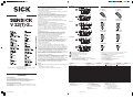
Lieferumfang: Betriebsanleitung, zwei M-12-Metallmuttern
Adernfarben: 1/brn = braun; 2/wht = weiß; 3/blu = blau; 4/blk = schwarz
1)
Controll-Eingang C, Programmierung: Schaltart L.ON/D.ON und
extern Teach-in
C = offen (nicht belegt): hellschaltend L.ON
C = + U
V
: dunkelschaltend D.ON
C = 0 V: Empfindlichkeits-Einstellung per „extern Teach-in“ aktiv
2)
L/D Steuerleitung Schaltart
L/D = offen (nicht belegt): dunkelschaltend D.ON
L/D = + U
V
: hellschaltend L.ON
L/D = 0 V: dunkelschaltend D.ON
V_ 12T-2_ 1__
V_ 12-2_ 1__
V_ 12T-2_ 4__
V_ 12-2_ 4__
1
Leitung oder Stecker M 12, 4-polig
Empfindlichkeits-Einsteller (Teach-in-Taste)
Befestigungs-Mutter (2x); SW 17, Metall
Anzeige-LED gelb
*)
*)
VT 12(T)-2... und VL 12-2...:
leuchtet permanent: Empfangssignal > Reservefaktor 2
blinkt: Empfangssignal < Reservefaktor 2, aber > Schaltschwelle 1
VS 12-2...: Power On – Sender aktiv
VE 12-2...: Lichtempfang > Schaltsschwelle 1
2
3
4
VT 12(T)-2...
3
3
1
1
12,3
4,4
22,3
4,4
2
4
2
4
54,5
4
M12x1 M12x1
34
34
65,5
2
2
22
18,5
7, 5
3
1
1
16,7
26,7
3
4
55
4
M12x1
34
34
66
2,5
22
18,5
7, 5
M12x1
2,5
4
VL 12-2...
55,3
1
1
4
M12x1 M12x1
34
34
66,3
1
2,8
2,8
22
18,5
7, 5
4
3
3
4
16,7
26,7
VS/VE 12-2...
VT 12T-2_ 112
VT 12T-2_ 132
brn
blu
blk
wht
L+
M
Q
C
1)
VT 12T-2_ 410
VT 12T-2_ 430
1
L
+
M
Q
C
3
4
2
brn
blu
blk
wht
1)
VL 12-2_ 132
VE 12-2_ 132
brn
blu
blk
wht
L+
M
Q
L/D
2)
VL 12-2_ 430
VE 12-2_ 430
1
L+
M
Q
L/D
3
4
2
brn
blu
blk
wht
2)
VS 12-2D 132
brn
blu
L+
M
VS 12-2D 430
1
L
+
M
3
brn
blu
1)
Tastgut 90 % Remission (bezogen auf
Standard Weiß nach DIN 5033);
100 x 100 mm
2)
Mittlere Lebensdauer 100.000 h bei
T
U
= +25 °C
3)
Mit Polarisationsfilter
4)
Controll-Eingang C
– Schaltart L.ON/D.ON und
– extern Teach-in
C = offen: hellschaltend L.ON
C = +U
V
: dunkelschaltend D.ON
C = 0 V: Empfindlichkeitseinstellung
per „extern Teach-in“ aktiv
5)
Grenzwerte
Restwelligkeit max. ±10 %
6)
Wählbar per Steuerleitung
(siehe Anschlusszeichnungen)
7)
Signallaufzeit bei ohmscher Last;
bei Hell-/Dunkelverhältnis 1:1
8)
Ohne Last
9)
A=U
V
-Anschlüsse verpolsicher
B = Ein- und Ausgänge verpolsicher
C = Störimpulsunterdrückung
D = Ausgänge kurzschlussfest (auto-reset)
V 12(T)-2 VT 12T-2..1. VT 12T-2..3. VL 12-2 VS 12-2D... VE 12-2
Typ Reflexions-Lichttaster
1)
Reflexions-Lichtschranken Einweg-Lichtschranken
Betriebsreichweite 100 mm 300 mm 2,3 m (PL 80A) 4m
Lichtfleckdurchmesser/Distanz ~20 mm/100 mm ~28 mm/300 mm ~80 mm/2 m ~100 mm/4 m
Lichtsender
2)
, Lichtart LED, Infrarotlicht LED, Infrarotlicht LED, Rotlicht
3)
LED, Infrarotlicht –
Empfindlichkeitseinstellung Teach-in
4)
Nein
Versorgungsspannung U
V
DC 10 ... 30 V
5)
Ausgangangsstrom I
A
max. ≤ 100 mA
Schaltausgang/-art
6)
NPN oder PNP – L.ON/D.ON (V 12-2P... = PNP; V 12-2N... = NPN)
Schaltfrequenz
7)
400/s 250/s
Stromaufnahme
8)
≤ 20 mA
Schutzart IP 67 (EN 60529)
VDE Schutzklasse III
Betriebsumgebungstemperatur –25 °C ... +70 °C
Schutzschaltung
9)
A, B, C, D
Gehäusematerial Hülse: Messing vernickelt/PA; Optik: PC
BA_V12T-2.pmd 30.12.02, 11:311

We reserve the right to make changes without prior notification
1202 GO
V 12(T)-2...
ENGLISH
Photoelectric switches series
Operating Instructions
Safety Specifications
‡ Read the operating instructions before starting operation.
‡ Connection, assembly, and settings only by competent technicians.
‡ Protect the device against moisture and soiling when operating.
‡ No safety component in accordance with EU machine guidelines.
Proper Use
The V 12(T)-2... photoelectric reflex switches are optoelectronic sensors
and are used for detection of optical, non-contanct detection of objects,
animals, and people.
Starting Operation
V 12(T)-2, energetic photoelectric proximity switch:
Mount sensor, set contacts and align it to the object to be detected.
Sensitivity setting:
You have two options for setting the sensitivity:
– Manual per Teach-in button
– Electronically, externally via control input C
Very simple programming. Press the Teach-in button 1x or activate control
input C (0 V) 1x. Sensitivity setting has been completed.
Feedback: Yellow LED indicator. Permanent storage of the “taught-in
switching threshold and hysteresis,” even if power is interrupted for longer
times.
Always position the scanning object at the target position in the light path.
Two Teach-in modes are available for your optimally adjusted sensitivity
setting.
Mode 1; large function reserves: applications:
Standard sensitivity; recommended for all standard applications.
Function reserve factor > 2 above switching threshold; short “Teach-in
time” (> 2 s ... < 7 s).
Press the Teach-in button or activate control input C (0 V)
(> 2 s ...< 7 s): Yellow LED indicator – goes off – lights after > 2 s again –
deactivate Teach-in signal. Sensitivity setting completed. Yellow LED
indicator lights after Teach-in process has been completed in mode 1.
A) Check application:
Remove the object to be scanned. Does the yellow LED go off? OK. Yellow
LED lights (background influence?): set high sensitivity; see mode 2.
Mode 2; precise switching point, high sensitivity: applications:
suitable for slight differences between object to be scanned and
background, for positioning tasks and for simple contrast detection.Small
switching hysteresis and small function reserve factor > 1 < 2 above
switching threshold; long “Teach-in time” (> 8 s).Press the Teach-in button
or activate control input C (0 V) (> 8 s): Yellow LED indicator – goes off –
lights after > 2 s again – blinks after > 8 s – deactivate Teach-in signal –
sensitivity setting completed! Yellow LED indicator lights continuously after
teach-in process has been completed in mode 2.
Check application: see A).
VL 12-2...; photoelectric reflex switch with polarizing filter, red light
Objects with shiny surfaces can be detected reliably thanks to the
integrated polarization filter. Mount sensor, set contacts and align the
sender beam to the reflector until the yellow LED indicator lights
continuously (pay attention to the specifications sheet). The red sender
light beam serves as an aid. Secure the sensor. Check whether the LED
goes off when the object to be detected interrupts the light beam. If the
yellow LED on VL 12-2... continues to be lit, object detection is influenced
by transparent or small objects. In this case, you need a sensor with
adjustable sensitivity (contact your SICK partner).
VS/VE 12-2…; through-beam photoelectric switch
Mount and set the contacts for the sensor sender VS 12-2... and receiver
VE 12-2... Align the sender VS 12-2 and receiver VE 12-2 to each other
until the yellow LED indicator lights continuously (pay attention to the
specifications sheet).
Secure the sensors, and check whether the LED goes off when the object
to be detected interrupts the light beam. If the yellow LED on VE 12-2...
continues to be lit, object detection is influenced by transparent or small
objects. In this case, you need a sensor with adjustable sensitivity (contact
your SICK partner).
Maintenance
SICK photoelectric switches do not require any maintenance. We
recommend that you clean the optical interfaces and check the screw
connections and plug-in connections at regular intervals.
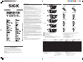
Supplied material: Operating instructions, two M 12 metal ring nut
Wiring colors: 1/brn = brown; 2/wht = white; 3/blu = blue; 4/blk = black
1)
Control input C, programming: Switching type L.ON/D.ON and
external Teach-in
C = open (not assigned): light-switching L.ON
C = + V
S
: dark-switching D.ON
C = 0 V: sensitivity setting per “external Teach-in” active
2)
L/D switching type control line
L/D = open (not assigned): dark-switching D.ON
L/D = + V
S
: light-switching L.ON
L/D = 0 V: dark-switching D.ON
V_ 12T-2_ 1__
V_ 12-2_ 1__
V_ 12T-2_ 4__
V_ 12-2_ 4__
1
Cable or plug M 12, 4-pin
Sensitivity adjustment (Teach-in button)
Mounting nuts (2x); SW 17, metal
Yellow LED indicator:
*)
*)
VT 12(T)-2... and VL 12-2...:
lights continuously: reception signal > reserve factor 2
blinks: reception signal < reserve factor 2, but > switching threshold 1
VS 12-2...: power on – sender active
VE 12-2...: light reception > switching threshold 1
2
3
4
VT 12(T)-2...
4
4
1
1
12.3
4.4
22.3
4.4
2
3
2
3
54.5
4
M12x1 M12x1
34
34
65.5
2
2
22
18.5
7. 5
3
1
1
16.7
26.7
3
4
55
4
M12x1
34
34
66
2.5
22
18.5
7. 5
M12x1
2.5
4
VL 12-2...
55.3
1
1
4
M12x1 M12x1
34
34
66.3
1
2.8
2.8
22
18.5
7. 5
4
3
3
4
16.7
26.7
VS/VE 12-2...
VT 12T-2_ 112
VT 12T-2_ 132
brn
blu
blk
wht
L+
M
Q
C
1)
VT 12T-2_ 410
VT 12T-2_ 430
1
L
+
M
Q
C
3
4
2
brn
blu
blk
wht
1)
VL 12-2_ 132
VE 12-2_ 132
brn
blu
blk
wht
L+
M
Q
L/D
2)
VL 12-2_ 430
VE 12-2_ 430
1
L+
M
Q
L/D
3
4
2
brn
blu
blk
wht
2)
VS 12-2D 132
brn
blu
L+
M
VS 12-2D 430
1
L
+
M
3
brn
blu
1)
Object to be detected with 90 %
remission (relating to standard white in
acc. with DIN 5033); 100 x 100
2)
Average service life 100,000 h at
T
A
= +25 °C
3)
With polarizing filter
4)
Control input C
– Switching type L.ON/D.ON and
– external Teach-in
C = open (not assigned): light-switching
L.ON
C = + V
S
: dark-switching D.ON
C = 0 V: sensitivity setting
per “external Teach-in” active
5)
Limits
Ripple max. ± 10 %
6)
Selectable per control wire
(see the connection drawings)
7)
Signal transit time with resistive load;
with light/dark ratio 1:1
8)
Without load
9)
A=V
S
connections reverse-polarity protected
B = Inputs and outputs reverse-polarity
protected
C = Interference pulse suppression
V 12(T)-2 VT 12T-2..1. VT 12T-2..3. VL 12-2 VS 12-2D... VE 12-2
Type Photoelectric proximity switches
1)
Photoelectric reflex switches
Through-beam photoelectric switches
Operating range 100 mm 300 mm 2.3 m (PL 80A) 4m
Light spot diameter/distance ~20 mm/100 mm ~28 mm/300 mm ~80 mm/2 m ~100 mm/4 m
Light source
2)
, light type LED, Infrarotlicht LED, infrared light LED, red light
3)
LED, infrared light –
Sensitivity setting Teach-in
4)
No
Supply voltage V
S
DC 10 ... 30 V
5)
Output current I
A
max. ≤ 100 mA
Switching output/-mode
6)
NPN or PNP – L.ON/D.ON (V 12-2P... = PNP; V 12-2N... = NPN)
Switching frequency
7)
400/s 250/s
Current consumption
8)
≤ 20 mA
Enclosure rating IP 67 (EN 60529)
VDE protection class III
Ambient operating temperature –25 °C ... +70 °C
Circuit protection
9)
A, B, C, D
Housing material Housing: Nickel-coated brass/PA; Optics: PC
BA_V12T-2.pmd 30.12.02, 11:312

Sous réserve de modifications
1202 GO
V 12(T)-2...
FRANÇAIS
Famille de barrières photoélectriques
Instructions de Service
Conseils de sécurité
‡ Lire les Instructions de Service avant la mise en marche.
‡ Installation, raccordement et réglage ne doivent être effectués que par
du personnel qualifié.
‡ Lors de la mise en service, protéger l’appareil de l’humidité et des
saletés.
‡ N’est pas un composant de sécurité au sens de la directive européenne
concernant les machines.
Utilisation correcte
La barrière réflex V 12(T)-2... est un capteur optoélectronique qui s’utilise
pour la saisie optique de choses, d’animaux et de personnes sans aucun
contact. Pour son fonctionnement.
Mise en service
V 12(T)-2, Détecteur réflex énergétique.
Monter le capteur, établir les contacts et le diriger vers l’objet à détecter.
Réglage de la sensibilité :
Vous disposez de 2 options pour effectuer le réglage de la sensibilité :
– réglage manuel à l’aide de la touche Teach-in (Apprentissage) et
– réglage électronique externe par l’entrée de commande C.
Programmation extrêmement facile : appuyer 1x sur la touche Teach-in
(Apprentissage) ou activer 1 x l’entrée de commande C (0 V) : le réglage
de la sensibilité est terminé.
Réaction : LED témoin jaune. Mémorisation permanente du « seuil de
commutation appris et de l’hystérésis », même en cas de coupure
arbitrairement longue de la tension.
Toujours placer l’objet à détecter dans le trajet de la lumière, dans la
position future prévue.
Vous disposez de deux modes d’apprentissage pour votre réglage optimal
de la sensibilité :
Mode 1 ; grande réserve de fonctionnement ; Applications :
Sensibilité standard ; recommandée pour toutes les applications standards.
Réserve de fonctionnement d’un facteur > 2 au-dessus du seuil de
commutation ; « Temps d’apprentissage » court (> 2 s et < 7 s).
Appuyer sur la touche Teach-in (Apprentissage) ou activer l’entrée de
commande C (0 V) (> 2 s et < 7 s) : LED témoin jaune – elle s’éteint –
puis s’allume de nouveau au bout de > 2 s – couper le signal
d’apprentissage. Réglage de la sensibilité terminé. La LED témoin jaune est
allumée lorsque le processus d’apprentissage en Mode 1 est terminé.
A) Contrôle de l’application :
Éloigner l’objet à détecter. La LED jaune s’éteint ? O.K. La LED est allumée
(influence de l’arrière-plan ?) : régler une sensibilité élevée, voir Mode 2.
Mode 2 ; point de commutation exact, haute sensibilité ; applications :
convient aux faibles différences objet à détecter/arrière-plan, aux tâches
de positionnement, à une détection aisée des contrastes.
Petite hystérésis de commutation et réserve de fonctionnement moindre,
facteur > 1 et < 2 au-dessus du seuil de commutation ; « Temps
d’apprentissage » long (> 8 s).
Appuyer sur la touche Teach-in (Apprentissage) ou activer l’entrée de
commande C (0 V) (> 8 s) : LED témoin jaune – elle s’éteint – puis
s’allume de nouveau au bout de > 2 s – et clignote après > 8 s – couper
le signal d’apprentissage – réglage de la sensibilité terminé ! La LED
témoin jaune clignote en permanence lorsque le processus
d’apprentissage en Mode 2 est terminé.
Contrôle de l’application : voir A).
VL 12-2... ; Barrière réflex avec filtre polariseur, lumière rouge
Le filtre polariseur intégré permet de détecter de façon fiable les objets
présentant une surface brillante. Monter le capteur, établir les contacts et
diriger le rayon émis vers le réflecteur jusqu’à ce que la LED jaune reste
allumée (tenir compte des valeurs de la fiche technique). Le rayon rouge
émis vous aidera dans cette tâche. Bloquez le capteur. Contrôlez que la
LED s’éteint lorsque l’objet à détecter interrompt le rayon de lumière. Si la
LED jaune au VL 12-2... reste allumée, c’est que la détection de l’objet est
influencée par les objets petits ou transparents. Dans un tel cas, vous avez
besoin d’un capteur à sensibilité réglable (adressez-vous à votre
concessionnaire SICK).
VS/VE 12-2… ; Barrière unidirectionnelle
Monter les capteurs émetteur VS 12-2... et récepteur VE 12-2... puis établir
les contacts. Diriger l’émetteur VS 12-2 et le récepteur VE 12-2 l’un vers
l’autre jusqu’à ce que la LED jaune reste allumée (tenir compte des valeurs
de la fiche technique).
Bloquez les capteurs, contrôlez que la LED jaune s’éteint lorsque l’objet à
détecter interrompt le rayon de lumière. Si la LED jaune au VE 12-2... reste
allumée, c’est que la détection de l’objet est influencée par les objets
petits ou transparents. Dans un tel cas, vous avez besoin d’un capteur à
sensibilité réglable (adressez-vous à votre concessionnaire SICK).
Maintenance
Les barrières lumineuses SICK ne nécessitent pas d’entretien. Nous
recommandons, à intervalles réguliers
- de nettoyer les surfaces optiques,
- de contrôler les assemblages vissés et les connexions à fiche et à prise.
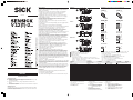
Fourniture: Notice d’emploi, deux écrous métalliques M12
Couleurs des brins : 1/brn = brun ; 2/wht = blanc ; 3/blu = bleu ; 4/blk = noir
1)
Entrée de commande C, programmation : type de commutation L.ON/
D.ON et Teach-in externe
C = vacant (non occupé) : commutation claire L.ON
C = + UV : commutation sombre D.ON
C = 0 V : Réglage de la sensibilité par «Teach-in externe» actif
2)
L/D Câble de commande Type de commutation
L/D = vacant (non occupé) : commutation sombre D.ON
L/D = + UV : commutation claire L.ON
L/D = 0 V : commutation sombre D.ON
V_ 12T-2_ 1__
V_ 12-2_ 1__
V_ 12T-2_ 4__
V_ 12-2_ 4__
1
Conducteur ou fiche M 12, 4 pôles
Réglage de la sensibilité (Touche Teach-in)
Écrou de fixation (2x) ; clé de 17, métal
LED témoin jaune
*)
*)
VT 12(T)-2... et VL 12-2...:
Reste allumée en permanence : signal reçu > facteur de réserve 2
Clignote : signal reçu < facteur de réserve 2 mais > seuil de commutation 1
VS 12-2... : Branché – émetteur actif
VE 12-2... : Lumière reçue > seuil de commutation 1
2
3
4
VT 12(T)-2...
3
3
1
1
12,3
4,4
22,3
4,4
2
4
2
4
54,5
4
M12x1 M12x1
34
34
65,5
2
2
22
18,5
7, 5
3
1
1
16,7
26,7
3
4
55
4
M12x1
34
34
66
2,5
22
18,5
7, 5
M12x1
2,5
4
VL 12-2...
55,3
1
1
4
M12x1 M12x1
34
34
66,3
1
2,8
2,8
22
18,5
7, 5
4
3
3
4
16,7
26,7
VS/VE 12-2...
VT 12T-2_ 112
VT 12T-2_ 132
brn
blu
blk
wht
L+
M
Q
C
1)
VT 12T-2_ 410
VT 12T-2_ 430
1
L
+
M
Q
C
3
4
2
brn
blu
blk
wht
1)
VL 12-2_ 132
VE 12-2_ 132
brn
blu
blk
wht
L+
M
Q
L/D
2)
VL 12-2_ 430
VE 12-2_ 430
1
L+
M
Q
L/D
3
4
2
brn
blu
blk
wht
2)
VS 12-2D 132
brn
blu
L+
M
VS 12-2D 430
1
L
+
M
3
brn
blu
1)
Matériel à détecter à 90 % de
luminance lumineuse (par rapport au
blanc de référence selon DIN 5033) ;
100 x 100 mm
2)
Durée de vie moyenne 100.000 h à
T
U
= +25 °C
3)
Avec filtre polariseur
4)
Entrée de commande C
– Type de commutation L.ON/D.ON et
– Teach-in externe
C = vacant (non occupé) : commutation
claire L.ON
C = + UV : commutation sombre D.ON
C = 0 V : Réglage de la sensibilité par
«Teach-in externe» actif
5)
Valeurs limites
Ondulation résiduelle maxi ±10 %
6)
Peut se sélectionner par le câble de
commande (voir dessins de raccordement)
7)
Temps de propagation du signal sous
charge ohmique ; pour un rapport clair/
sombre de 1 : 1
8)
Sans charge
9)
A=Raccordements U
V
protégés
contre les inversions de polarité
B = Entrées et sorties protégées contre les
inversions de polarité
C=
Suppression des impulsions parasites
D=Sorties protégées contre les courts-
circuits (auto-reset)
V 12(T)-2 VT 12T-2..1. VT 12T-2..3. VL 12-2 VS 12-2D... VE 12-2
Type Détecteur réflex
1)
Barrières réflex Barrières unidirectionnelles
Portées pratiques 100 mm 300 mm 2,3 m (PL 80A) 4 m
Diamètre du spot lumineux/Distance ~20 mm/100 mm ~28 mm/300 mm ~80 mm/2 m ~100 mm/4 m
Émetteur de lumière
2)
, type de lumière LED, lumière infrarouge
LED, lumière infrarouge
LED, lumière rouge
3)
LED, lumière infrarouge
–
Réglage de la sensibilité Teach-in
4)
Non
Tension d'alimentation U
V
DC 10 ... 30 V
5)
Courant de sortie I
maxi
≤ 100 mA
Sortie/Type de commutation
6)
NPN ou PNP – L.ON/D.ON (V 12-2P... = PNP; V 12-2N... = NPN)
Fréquence de commutation
7)
400/s 250/s
Consommation
8)
≤ 20 mA
Type de protection IP 67 (EN 60529)
Classe de protection VDE III
Température ambiante –25 °C ... +70 °C
Circuits de protection
9)
A, B, C, D
Matériau du boîtier Manchon : laiton nickelé/PA ; Optique : PC

Con riserva di modifiche
1202 GO
V 12(T)-2...
ITALIANO
Famiglia di fotocellule
Instruzioni per l'uso
Avvertimenti di sicurezza
‡ Leggere prima della messa in esercizio.
‡ Allacciamento, montaggio e regolazione solo da parte di personale
qualificato.
‡ Durante la messa in esercizio proteggere da umidità e sporcizia.
‡ Non componente di sicurezza secondo la Direttiva macchine EN.
Impiego conforme allo scopo
La barriera luminosa a riflessione V 12(T)-2... è un sensore optoelettronico
che viene impiegatoper il rilevamento ottico a distanza di oggetti, animali e
persone. Per l’esercizioè necessario un riflettore.
Messa in esercizio
V 12(T)-2, tastatore a riflessione energetico.
Montare il sensore, realizzare i contatti e allinearlo sull’oggetto.
Regolazione della sensibilità:
Per la regolazione della sensibilità potete scegliere tra due opzioni:
– regolazione manuale con tasto di Teach-in oppure
– regolazione elettronica, dall’esterno, tramite ingresso di controllo C.
Massima semplicità di programmazione: premere 1 volta il tasto di Teach-
in o attivare 1 volta l’ingresso di controllo C (0 V): la regolazione della
sensibilità è già completata.
Feedback: Spia gialla. Memorizzazione permanente della soglia di
commutazione e dell’isteresi „imparate“, anche in caso di prolungate
interruzioni dell’alimentazione elettrica.
Posizionare sempre l’oggetto nel fascio di luce nella posizione richiesta.
Per consentire una regolazione ottimale della sensibilità, sono disponibili
due diverse modalità di Teach-in.
Modalità 1; grande riserva di funzionamento; applicazioni:
sensibilità standard; consigliata per tutte le applicazioni standard.
Fattore di riserva di funzionamento > 2 oltre soglia di commutazione;
„tempo di Teach-in“ molto breve (> 2 s ... < 7 s).
Premere il tasto di Teach-in o attivare l’ingresso di controllo C (0 V) (> 2 s
... < 7 s): la spia gialla si spegne e si riaccende dopo > 2 s; disattivare il
segnale di Teach-in. Termine della regolazione della sensibilità. La spia
gialla rimane accesa dopo il processo di Teach-in in modalità 1.
A) Controllare l’applicazione:
Rimuovere l’oggetto. La spia gialla si spegne? OK. La spia gialla rimane
accesa (influsso dello sfondo?): impostare alta sensibilità, v. modalità 2.
Modalità 2; punto di commutazione esatto, alta sensibilità; applicazioni:
adatta per applicazioni con scarsa differenziazione tra oggetto e sfondo,
applicazioni di posizionamento, riconoscimento semplice del contrasto.
Isteresi ridotta, riserva di funzionamento ridotta, fattore > 1 < 2 oltre soglia
di commutazione. „Tempo di Teach-in“ più lungo (> 8 s).
Premere il tasto di Teach-in o attivare l’ingresso di controllo C (0 V) (> 8 s):
la spia gialla si spegne, si riaccende dopo > 2 s e lampeggia > 8 s;
disattivare il segnale di Teach-in. Termine della regolazione della sensibilità.
La spia gialla lampeggia in modo permanente dopo il processo di Teach-in
in modalità 2.
Controllare l’applicazione: v. A).
VL 12-2...; tastatore a riflessione con filtro di polarizzazione, luce rossa
Il filtro di polarizzazione integrato consente di riconoscere in modo
affidabile gli oggetti con superficie lucida. Montare il sensore, realizzare i
contatti e dirigere il fascio luminoso sul riflettore finché la spia gialla rimane
accesa in modo permanente (attenersi ai valori della scheda tecnica). Il
fascio di luce rossa dell’emettitore facilita il lavoro. Assicurare il sensore.
Controllare che la spia si spenga non appena l’oggetto interrompe il fascio
di luce. Se la spia del VL 12-2… rimane accesa, il riconoscimento è
ostacolato dalla trasparenza o dalle piccole dimensioni dell’oggetto. In
questo caso sarà necessario installare un sensore con sensibilità regolabile
(per maggiori informazioni rivolgersi al rappresentante SICK).
VS/VE 12-2…; fotocellula unidirezionale
Montare l’emettitore VS 12-2... e il ricevitore VE 12-2... e realizzare i
contatti. Allineare reciprocamente l’emettitore VS 12-2 e il ricevitore VE 12-
2 finché la spia gialla rimane accesa in modo permanente (attenersi ai
valori della scheda tecnica).
Assicurare i sensori. Controllare che la spia si spenga non appena l’oggetto
interrompe il fascio di luce. Se la spia del VE 12-2… rimane accesa, il
riconoscimento è ostacolato dalla trasparenza o dalle piccole dimensioni
dell’oggetto. In questo caso sarà necessario installare un sensore con
sensibilità regolabile (per maggiori informazioni rivolgersi al rappresentante
SICK).
Manutenzione
Le barriere luminose SICK non richiedono manutenzione. Si consiglia
- di pulire regolarmente le superfici limite ottiche,
- di controllare regolarmente gli avvitamenti e i collegamenti a spina.
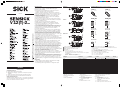
Corredo di fornitura: manuale, due dadi in metallo M-12
Colore fili: 1/brn = marrone; 2/wht = bianco; 3/blu = blu; 4/blk = nero
1)
Ingresso di controllo C, programmazione: tipo di commutazione L.ON/D.ON
e Teach-in esterno
C = aperto (non collegato): comm. a chiaro L.ON
C = + U
V
: comm. a scuro D.ON
C = 0 V: regolazione sensibilità tramite „Teach-in esterno“ attiva
2)
L/D Cavo di comando/tipo di commutazione
L/D = aperto (non collegato): comm. a scuro D.ON
L/D = + U
V
: comm. a chiaro L.ON
L/D = 0 V: comm. a scuro D.ON
V_ 12T-2_ 1__
V_ 12-2_ 1__
V_ 12T-2_ 4__
V_ 12-2_ 4__
1
Cavo o connettore M 12, 4 poli
Regolatore di sensibilità (tasto di Teach-in)
Dado di fissaggio (2x); SW 17, metallo
Spia gialla
*)
*)
VT 12(T)-2... e VL 12-2...:
luce fissa: segnale di ricezione > fattore di riserva 2
lampeggiante: segnale di ricezione < fattore di riserva 2, ma > soglia di
commutazione 1
VS 12-2...: Power On – sensore attivo
VE 12-2...: Ricezione luce > soglia di comm. 1
2
3
4
VT 12(T)-2...
3
3
1
1
12,3
4,4
22,3
4,4
2
4
2
4
54,5
4
M12x1 M12x1
34
34
65,5
2
2
22
18,5
7, 5
3
1
1
16,7
26,7
3
4
55
4
M12x1
34
34
66
2,5
22
18,5
7, 5
M12x1
2,5
4
VL 12-2...
55,3
1
1
4
M12x1 M12x1
34
34
66,3
1
2,8
2,8
22
18,5
7, 5
4
3
3
4
16,7
26,7
VS/VE 12-2...
VT 12T-2_ 112
VT 12T-2_ 132
brn
blu
blk
wht
L+
M
Q
C
1)
VT 12T-2_ 410
VT 12T-2_ 430
1
L
+
M
Q
C
3
4
2
brn
blu
blk
wht
1)
VL 12-2_ 132
VE 12-2_ 132
brn
blu
blk
wht
L+
M
Q
L/D
2)
VL 12-2_ 430
VE 12-2_ 430
1
L+
M
Q
L/D
3
4
2
brn
blu
blk
wht
2)
VS 12-2D 132
brn
blu
L+
M
VS 12-2D 430
1
L
+
M
3
brn
blu
1)
Oggetto con remissione del 90 %
(riferita a bianco standard a norma
DIN 5033); 100 X 100 mm
2)
Durata media 100.000 h per
T
U
= +25 °C
3)
Con filtro di polarizzazione
4)
Ingresso di controllo C
– tipo di commutazione L.ON/D.ON e
– Teach-in esterno
C = aperto (non collegato): comm. a
chiaro L.ON
C = + U
V
: comm. a scuro D.ON
C = 0 V: regolazione sensibilità tramite
„Teach-in esterno“ attiva
5)
Valori limite
Ondulazione residua max. ±10 %
6)
Selezionabile tramite cavo di controllo
(v. schema di allacciamento)
7)
Tempo di transito segnale con carico ohmico;
con rapporto chiaro/scuro 1:1
8)
Senza carico
9)
A=U
V
-collegamenti con protez. contro
inversione di poli
B = Ingressi e uscite protetti dall’inversione
della polarità
C = Soppressione impulsi di disturbo
D = Uscite a prova di corto circuito (auto-reset)
V 12(T)-2 VT 12T-2..1. VT 12T-2..3. VL 12-2 VS 12-2D... VE 12-2
Tipo Tastatori a riflessione
1)
Fotocellule a riflessione Fotocellule unidirezionali
Distanze di lavoro 100 mm 300 mm 2,3 m (PL 80A) 4 m
Diametro del punto luminoso/Distanza ~20 mm/100 mm ~28 mm/300 mm ~80 mm/2 m ~100 mm/4 m
Emettitore di luce
2)
, tipo di luce LED, luce infrarossa LED, luce infrarossa LED, luce rossa
3)
LED, luce infrarossa
–
Regolazione della sensibilità Teach-in
4)
No
Tensione di alimentazione U
V
DC 10 ... 30 V
5)
Corrente di uscita max. I
max
≤ 100 mA
Uscita/tipo di commutazione
6)
NPN o PNP – L.ON/D.ON (V 12-2P... = PNP; V 12-2N... = NPN)
Frequenza di commutazione
7)
400/s 250/s
Assorbimento di corrente
8)
≤ 20 mA
Tipo di protenzione IP 67 (EN 60529)
Classe di protezione VDE III
Temperatura ambiente circostante –25 °C ... +70 °C
Commutazioni di protezione
9)
A, B, C, D
Materiale del contenitore Custodia: ottone nichelato/PA; ottica: PC
-
 1
1
-
 2
2
-
 3
3
-
 4
4


SICK SENSICK V12(T)-2 Istruzioni per l'uso
- Tipo
- Istruzioni per l'uso
in altre lingue
- français: SICK SENSICK V12(T)-2 Mode d'emploi
Documenti correlati
-
SICK SENSICK V18 L - Laser Istruzioni per l'uso
-
-
-
-
-
-
-
-
-