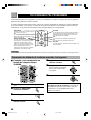
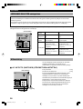
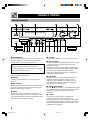
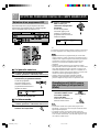
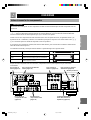
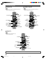
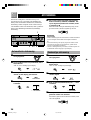
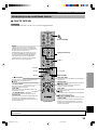
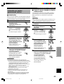
Yamaha RX-V396 Manuale del proprietario
- Categoria
- Lettori minidisc
- Tipo
- Manuale del proprietario

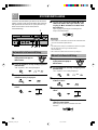
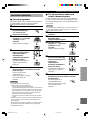
OWNER’S MANUAL
MODE D’EMPLOI
BEDIENUNGSANLEITUNG
BRUKSANVISNING
MANUALE DI ISTRUZIONI
MANUAL DE INSTRUCCIONES
GEBRUIKSAANWIJZING
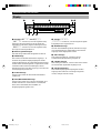
RX-V396
Natural Sound AV Receiver
Ampli-tuner audio-vidéo
RX-V396
G B
1/20/0, 6:07 PM

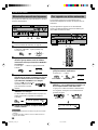
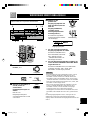
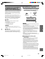
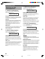
CAUTION
CAUTION: READ THIS BEFORE OPERATING YOUR UNIT.
1. To assure the finest performance, please read this
manual carefully. Keep it in a safe place for future
reference.
2. Install this unit in a cool, dry, clean place — away
from windows, heat sources, sources of excessive
vibration, dust, moisture and cold. Avoid sources of
humming (transformers, motors). To prevent fire or
electrical shock, do not expose the unit to rain or
water.
3. Never open the cabinet. If something drops into the
unit, contact your dealer.
4. Do not use force on switches, controls or connection
wires. When moving the unit, first disconnect the
power cord and then the wires connected to other
component. Never pull the wires themselves.
5. The openings on the cover assure proper ventilation
of the unit. If these openings are obstructed, the
temperature inside the unit will rise rapidly.
Therefore, avoid placing objects against these
openings, and install the unit in a well-ventilated area
to prevent fire and damage.
Be sure to allow a space of at least 20 cm behind,
20 cm on both sides and 30 cm above the top panel
of the unit to prevent fire and damage.
6. The voltage used must be the same as that specified
on this unit. Using this unit with a higher voltage than
specified is dangerous and may result in fire or other
accidents. YAMAHA will not be held responsible for
any damage resulting from the use of this unit with a
voltage other than that specified.
7. Digital signals generated by this unit may interfere
with other component such as tuners, receivers and
TVs. Move this unit farther away from such
component if interference is observed.
8. Always set VOLUME to the “m” position before
starting the audio source play. Increase the volume
gradually to an appropriate level after playback has
been started.
9. Do not attempt to clean the unit with chemical
solvents; this might damage the finish. Use a clean,
dry cloth.
10. Be sure to read the “TROUBLESHOOTING” section
regarding common operating errors before
concluding that the unit is faulty.
11. When not planning to use this unit for a long period
of time (e.g., a vacation), disconnect the AC power
cord from the wall outlet.
12. To prevent lightning damage, disconnect the AC
power cord and disconnect the antenna cable when
there is an electrical storm.
13. Grounding or polarization — Precautions should be
taken so that the grounding or polarization of the unit
is not defeated.
14. AC outlet — Do not connect audio component to the
AC outlet on the rear panel if that component
requires more power than the outlet is rated to
provide.
This unit is not disconnected from the AC power source
as long as it is connected to the wall outlet, even if this
unit itself is turned off. This state is called the standby
mode. In this state, this unit is designed to consume a
very small quantity of power.
■ For U.K. customers
If the socket outlets in the home are not suitable for the plug
supplied with this appliance, it should be cut off and an
appropriate 3 pin plug fitted. For details, refer to the
instructions described below.
Note
• The plug severed from the mains lead must be destroyed, as a
plug with bared flexible cord is hazardous if engaged in a live
socket outlet.
■ Special Instructions for U.K. Model
IMPORTANT
THE WIRES IN MAINS LEAD ARE COLOURED IN
ACCORDANCE WITH THE FOLLOWING CODE:
Blue: NEUTRAL
Brown: LIVE
As the colours of the wires in the mains lead of this
apparatus may not correspond with the coloured
markings identifying the terminals in your plug, proceed
as follows:
The wire which is coloured BLUE must be connected to
the terminal which is marked with the letter N or
coloured BLACK. The wire which is coloured BROWN
must be connected to the terminal which is marked with
the letter L or coloured RED.
Making sure that neither core is connected to the earth
terminal of the three pin plug.
0101V396caution_EN 1/7/0, 2:25 PM2

EnglishBASIC OPERATION
ADVANCED OPERA
TION APPENDIX
INTRODUCTION PREPARATION
1
FEATURES
5-Channel Power Amplification
◆ Minimum RMS Output
(0.06% THD, 20 Hz – 20 kHz)
Main: 60 W + 60 W (8 Ω)
Center: 60 W (8 Ω)
Rear: 60 W + 60 W (8 Ω)
Multi-mode Digital Sound Field
Processing
◆ Digital Sound Field Processor (DSP)
◆ Dolby Digital Decoder
◆ Dolby Pro Logic Decoder
◆ CINEMA DSP: Theater-like Sound Experience by
the Combination of YAMAHA DSP Technology
and Dolby Digital or Dolby Pro Logic
◆ Automatic Input Balance Control for Dolby Pro
Logic decoding
Sophisticated FM/AM Tuner
◆ 40-Station Random Access Preset Tuning
◆ Automatic Preset Tuning
◆ Preset Station Shifting Capability (Preset Editing)
Other Features
◆ “SET MENU” which Provides You with 10 Items
for Optimizing This Unit for Your Audio/Video
System
◆ Test Tone Generator for Easier Speaker Balance
Adjustment
◆ 6-Channel External Decoder Input for Other Future
Formats
◆ 2 Optical/1 Coaxial Digital Signal Input Terminals
◆ SLEEP Timer
◆ Remote Control with Preset Manufacturer Codes
INTRODUCTION
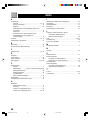
CONTENTS
Manufactured under license from Dolby
Laboratories. “Dolby”, “Pro Logic” and the
double-D symbol are trademarks of Dolby
Laboratories. Confidential Unpublished Works.
©1992 – 1997 Dolby Laboratories, Inc. All
rights reserved.
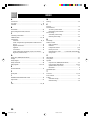
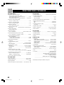
PREPARATION
SPEAKER SETUP....................................................... 8
CONNECTIONS.......................................................... 9
ADJUSTING THE SPEAKER BALANCE ............ 17
BASIC OPERATION
PLAYING A SOURCE .............................................. 19
DIGITAL SOUND FIELD PROCESSOR (DSP)
EFFECT .................................................................. 22
SOUND FIELD PROGRAM .................................... 23
TUNING ..................................................................... 26
RECORDING A SOURCE ON TAPE, MD OR
VIDEO CASSETTE ............................................... 30
ADVANCED OPERATION
SET MENU................................................................. 31
DELAY TIME AND SPEAKER
OUTPUT LEVELS ................................................. 35
SLEEP TIMER .......................................................... 37
PRESET REMOTE CONTROL .............................. 38
APPENDIX
TROUBLESHOOTING ............................................ 45
SPECIFICATIONS.................................................... 48
GLOSSARY................................................................ 49
INDEX ........................................................................ 50
INTRODUCTION
FEATURES .................................................................. 1
CONTENTS ................................................................. 1
GETTING STARTED ................................................. 2
CONTROLS AND FUNCTIONS ............................... 4
y indicates a tip for your operation.
0102V39601-07_EN 1/7/0, 2:25 PM1

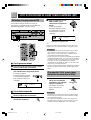
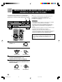
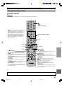
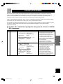
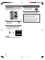
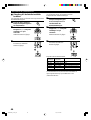
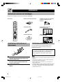
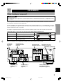
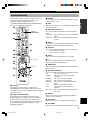
2
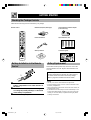
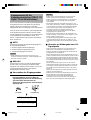
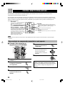
GETTING STARTED
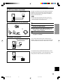
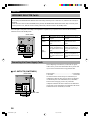
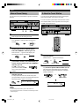
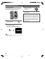
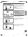
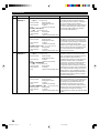
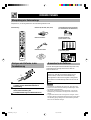
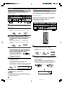
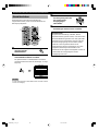
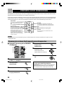
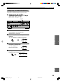
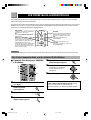
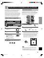
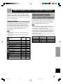
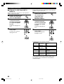
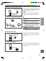
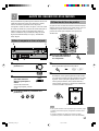
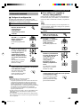
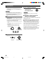
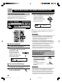
Checking the Package Contents
Check that the following items are included in your package.
2
1
3
Remote control Batteries (AAA, R03, UM-4 type) 75-ohm/300-ohm antenna adapter
(U.K. model only)
Indoor FM antenna Quick reference card
Connection guide
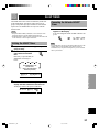
Battery Installation in the Remote
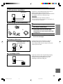
Control
1 Turn the remote control over and slide the
battery compartment cover in the direction of
the arrow.
2 Insert the batteries (AAA, R03 or UM-4 type)
according the polarity markings on the inside
of the battery compartment.
3 Close the battery compartment cover.
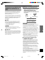
Battery Replacement
If the remote control operates only when it is close to the
unit, the batteries are weak. Replace all the batteries with
new ones.
Be sure to replace the batteries within about two minutes.
If it takes longer than two minutes, the codes preset for
the remote control will return to the factory settings.
(Refer to pages 38 to 44 about the remote control.)
Notes
• Use only AAA, R03 or UM-4 batteries for replacement.
• Be sure the battery polarity is correct. (See the illustration inside
the battery compartment.)
• Remove the batteries if the remote control will not be used for an
extended period of time.
• If the batteries have leaked, dispose of them immediately. Avoid
touching the leaked material or letting it come into contact with
clothing, etc. Clean the battery compartment thoroughly before
installing new batteries.
AM loop antenna
0102V39601-07_EN 1/7/0, 2:25 PM2

3
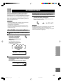
EnglishBASIC OPERATION
ADVANCED OPERA
TION APPENDIX
INTRODUCTION PREPARATION
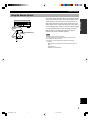
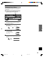
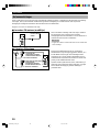
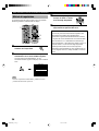
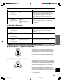
Using the Remote Control
The remote control transmits a directional infrared beam. Be
sure to aim the remote control directly at the infrared sensor
during operation. When the sensor is covered or there is a
large object between the remote control and the sensor, the
sensor cannot receive signals. The sensor may not be able to
receive signals properly when it is exposed to direct sunlight
or a strong artificial light (such as a fluorescent or strobe
light). In this case, change the direction of the light or
reposition the unit to avoid direct lighting.
Notes
• Handle the remote control with care.
• Do not spill water, tea or other liquids on the remote control.
• Do not drop the remote control.
• Do not leave or store the remote control in the following
conditions:
– high humidity or temperature such as near a heater, stove or
bath;
– dusty places; or
– extremely low temperature.
GETTING STARTED
Remote control
sensor
Within approximately 6 m
(20 feet)
0102V39601-07_EN 1/7/0, 2:25 PM3

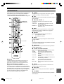
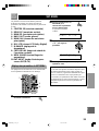
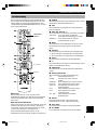
4
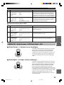
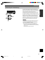
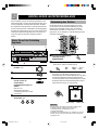
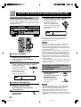
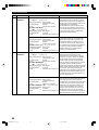
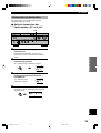
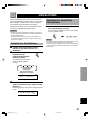
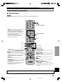
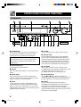
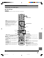
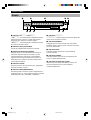
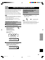
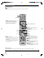
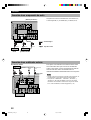
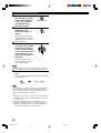
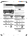
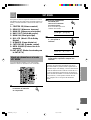
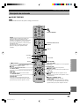
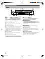
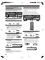
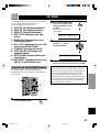
LR
–
+
–
+
12 3 4 65
7890qwertyu i o
6 VOLUME
Turn this control to turn up or down the volume.
7 PHONES jack
Connect the headphones to the PHONES jack. You can
listen to the sound to be output from the main speakers
through the headphones.
When using headphones only, set both SPEAKERS A and B
to the OFF position and press EFFECT to turn off the effect
speakers (center and rear) (so that no DSP program
indicator lights up on the display).
8 SPEAKERS
Set A or B (or both A and B) to the ON position for the main
speaker system (connected to this unit) that you want to use.
Set the button(s) to the OFF position for the main speaker
system that you don’t want to use.
9 PROGRAM selector
Press l or h to select a DSP program when the effect
speakers (center and rear) are turned on. The selected
program indicator lights up on the display.
0 EFFECT
Press this button to turn on or off the effect speakers (center
and rear). If you turn them off, all Dolby Digital audio
signals are directed to the right and left main speakers. In
that case, the output levels of the right and left speakers may
not match.
CONTROLS AND FUNCTIONS
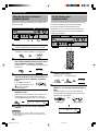
Front Panel
1 STANDBY/ON
Press this switch to turn on the power of this unit or to set
this unit in the standby mode. Before turning the power on,
set VOLUME to the “m” position.
Standby mode
In this mode, this unit consumes a very small quantity of
power to receive infrared-signals from the remote
control.
2 Remote control sensor
This receives signals from the remote control.
3 Display
This shows various information. (Refer to page 6 for
details.)
4 INPUT MODE
Press this button to select the input mode between AUTO
and ANALOG for the DVD/LD, TV/digital TV and satellite
tuner sources.
5 INPUT
Turn this selector to select the input source (VCR, SAT/D-
TV, DVD/LD, TUNER, CD, AUX) that you want to listen
to or watch. The name of the selected input source appears
on the display.
0102V39601-07_EN 1/18/0, 3:20 PM4

5
EnglishBASIC OPERATION
ADVANCED OPERA
TION APPENDIX
INTRODUCTION PREPARATION
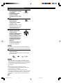
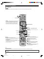
q Tone controls
These controls are only effective for the sound from the
main speakers.
a) BASS
Turn this control clockwise to increase or counterclockwise
to decrease the low-frequency response. The “0” position
produces a flat response.
b) TREBLE
Turn this control clockwise to increase or counterclockwise
to decrease the high-frequency response. The “0” position
produces a flat response.
w TAPE/MD MON / EXT. DECODER
Press this button to select a tape or an MD source. The
“TAPE/MD MONITOR” indicator lights up on the display.
When you press the button next, the “TAPE/MD
MONITOR” indicator goes off, “EXT. DECODER” appears
on the display and you can listen to a source connected to
the EXTERNAL DECODER INPUT terminals.
e BALANCE
This control is only effective for the sound from the main
speakers.
Turn the control to adjust the balance of the output volume
from the right and left main speakers to compensate for
sound imbalance caused by the speaker location or listening
room conditions.
r A/B/C/D/E
Press this button to select one of a group (A to E) of preset
stations.
t PRESET/TUNING
When “ z ” appears
This button is used to select a preset station number (1 to 8).
Press h to select a higher and l to select a lower preset
station number.
When “ z ” goes off
This button is used for tuning. Press h to tune in to higher
frequencies, and l to tune in to lower frequencies.
y PRESET/TUNING, EDIT
Press this button to turn on or off “ z ” on the display and
switch the function between for storing a broadcasting
station (preset tuning) and for tuning. This button is also
used to exchange the assignment of two preset stations with
each other.
u FM/AM
Press this button to switch the reception band between FM
and AM.
i MEMORY (MAN’L/AUTO FM)
Press this button to store the broadcasting stations. Hold
down this button for more than three seconds to begin
automatic preset tuning.
o TUNING MODE (AUTO/MAN’L MONO)
Press this button to switch the tuning mode between
automatic and manual. To use the automatic tuning method,
press this button so that the “AUTO” indicator lights up on
the display. To use the manual tuning method, press this
button so that the “AUTO” indicator goes off.
CONTROLS AND FUNCTIONS
0102V39601-07_EN 1/7/0, 2:25 PM5

6
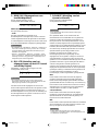
Display
6 x indicator
“ x ” lights up when the built-in digital sound
field processor is on.
7 MEMORY indicator
This flashes for about five seconds after pressing
MEMORY. During this period, the displayed station can be
stored in the memory.
8 AUTO indicator
This lights up when the unit is in the automatic tuning
mode.
9 STEREO indicator
This lights up when an FM stereo broadcast with sufficient
signal strength is being received.
0 Signal-level indicator
This indicates the signal level of the station being received.
If multipath interference is detected, the indication
decreases.
12 3 4
5
67
8
9
0
CONTROLS AND FUNCTIONS
1 g and o indicators
“ g ” lights up when the built-in Dolby Digital
decoder is on and the signals of the selected source are
encoded with Dolby Digital. “ o ” lights up when
the built-in Dolby Pro Logic decoder is on.
2 DSP program indicators
The name of the selected DSP program lights up.
3 Multi-information display
This display shows various information: for example the
name of the selected input source and the various settings
during adjustment with the SET MENU. The current station
frequency and band (FM or AM) also appear when the tuner
is selected as the input source.
4 SLEEP indicator
This lights up while the built-in SLEEP timer is on.
5 TAPE/MD MONITOR indicator
This lights up when the tape deck or MD recorder, etc. is
selected as the input source by pressing TAPE/MD MON /
EXT. DECODER (or TAPE/MD).
0102V39601-07_EN 2/10/0, 8:28 AM6

7
EnglishBASIC OPERATION
ADVANCED OPERA
TION APPENDIX
INTRODUCTION PREPARATION
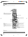
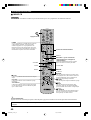
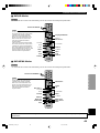
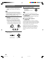
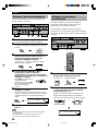
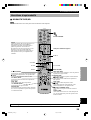
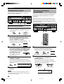
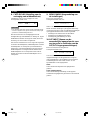
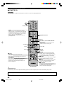
Remote Control
1 Indicator
This flashes in red when pressing a button on the remote
control. If it flashes rapidly several times, press the selected
button again.
2 Component selector buttons
Press one of these buttons which corresponds to the
component you want to control with the remote control.
(The proper code must be set for your component. Refer to
“Setup codes” on page 43.) When the component selector
button has been pressed, the remote control is set to that
component operation mode.
3 POWER
Each time you press this button, the unit switches between
the power on and standby mode.
4 TEST
Press this button to output the test tone for each speaker.
5 A/B/C/D/E, PRESET +/–
These buttons are used to select a preset station.
A/B/C/D/E: To select one of a group (A to E) of preset
stations
PRESET +/–: To select a preset station number (1 to 8)
6 MUTE
Press this button to mute the sound. To cancel mute, press
this button again.
7 VOLUME
These buttons are used to adjust the volume level.
u: To turn up the volume
d: To turn down the volume
8 SLEEP
Press this button to set the SLEEP timer.
9 +/–
These buttons adjust the settings of the SET MENU and
TIME/LEVEL mode.
0 TIME/LEVEL
Press this button to select the items in the TIME/LEVEL
mode.
q Input selector buttons
These buttons select the input source.
CD: To play a CD
TUNER: To listen to an FM or AM broadcast
TAPE/MD: To play a tape or MD
DVD/LD: To play a DVD or LD
SAT/D-TV: To watch a TV or satellite broadcast
VCR: To play a video cassette
AUX: To use another audio component
EXT. DEC.: To play other multi-channel source
w EFFECT
Press this button to turn on or off the effect speakers (center
and rear).
e PRG+, PRG–
Press these buttons to select a DSP program.
r SET MENU
Press this button to select the items in the SET MENU.
CONTROLS AND FUNCTIONS
1
2
3
q
w
e
r
4
5
6
7
8
9
0
TV VOLUME
TV INPUT
Press AMP(TUNER).
This section describes basic operation of this unit with the
remote control. First, press AMP(TUNER) on the
component selector. Refer to “PRESET REMOTE
CONTROL” on page 38 for full details.
0102V39601-07_EN 1/18/0, 3:20 PM7

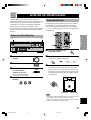
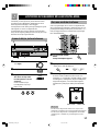
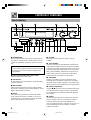
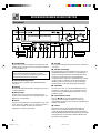
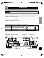
8
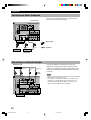
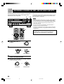
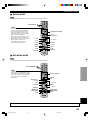
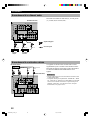
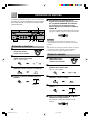
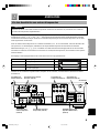
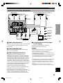
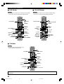
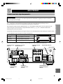
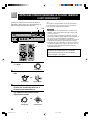
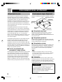
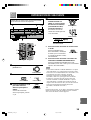
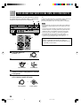
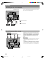
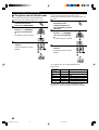
SPEAKER SETUP
Speaker Placement
Refer to the following diagram when you place the
speakers.
Speakers to Be Used
This unit is designed to provide the best sound-field quality
with a 5-speaker system, using main speakers, rear speakers
and a center speaker. If you use different brands of speakers
(with different tonal qualities) in your system, the tone of a
moving human voice and other types of sound may not shift
smoothly. We recommend that you use speakers from the
same manufacture or speakers with the same tonal quality.
The main speakers are used for the main source sound plus
the effect sounds. They will probably be the speakers from
your present stereo system. The rear speakers are used for
the effect and surround sounds, and the center speaker is for
the center sounds (dialog, vocals, etc.). If for some reason it
is not practical to use a center speaker, you can do without
it. Best results, however, are obtained with the full system.
The main speakers should be high-performance models and
have enough power-handling capacity to accept the
maximum output of your audio system. The other speakers
do not have to be equal to the main speakers. For precise
sound localization, however, it is ideal to use high-
performance models that can reproduce sounds over the full
range for the center speaker and the rear speakers.
■ Use of a subwoofer expands your
sound field
It is also possible to further expand your system with the
addition of a subwoofer. The use of a subwoofer is effective
not only for reinforcing bass frequencies from any or all
channels, but also for reproducing the LFE (low frequency
effect) channel with high fidelity when playing back a
source encoded with Dolby Digital. The YAMAHA Active
Servo Processing Subwoofer System is ideal for natural and
lively bass reproduction.
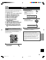
Main
speaker (L)
Center speaker
Main speaker (R)
Subwoofer
Rear speaker (L)
Rear speaker (R)
1.8 m
■ Main speakers
Place the right and left main speakers an equal distance
from the ideal listening position. The distance of each
speaker from each side of the TV monitor should be the
same.
■ Rear speakers
Place these speakers behind your listening position, facing
slightly inwards, nearly 1.8 m (approx. 6 feet) above the
floor.
■ Center speaker
Align the front face of the center speaker with the front face
of your TV monitor. Place the speaker as close to the
monitor as possible, such as directly over or under the
monitor and centrally between the main speakers.
Note
• If the center speaker is not used, the sound will be heard from the
right and left main speakers. In that case, “CENTER SP” in the
SET MENU is set to the NONE position. (Refer to page 32 for
details.)
■ Subwoofer
The position of the subwoofer is not so critical, because low
bass sounds are not highly directional. But it is better to
place the subwoofer near the main speakers. Turn it slightly
toward the center of the room to reduce the wall reflections.
CAUTION
Some types of speakers interfere with a TV monitor. If
this problem occurs, move the speakers away from the
monitor. If you cannot avoid installing the center speaker
or subwoofer near the TV monitor, use magnetically
shielded speakers.
PREPARATION
0103V39608-18_EN 1/7/0, 2:25 PM8

9
EnglishBASIC OPERATION
ADVANCED OPERA
TION APPENDIX
INTRODUCTION
PREPARATION
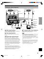
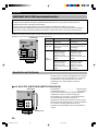
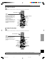
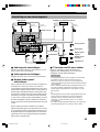
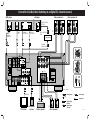
CONNECTIONS
Before Connecting Components
CAUTION
Never connect this unit and other components to mains power until all connections between components have been
completed.
Be sure all connections are made correctly, that is to say L (left) to L, R (right) to R, “+” to “+” and “–” to “–”. Some
components require different connection methods and have different terminal names. Refer to the instructions for each
component to be connected to this unit.
When you connect other YAMAHA audio components (such as a tape deck, MD recorder and CD player or changer), connect
it to the terminals with the same number labels as !, #, $ etc. YAMAHA applies this labeling system to all its products.
Use RCA-type pin plug cables for connecting audio/video components with the exception described later.
The input and output terminals for pin plugs can be distinguished as follows:
Yellow video signals (composite)
White analog audio signals for the left channel
Red analog audio signals for the right channel
coaxial digital signals
After completing all connections, check them again to make sure they are correct.
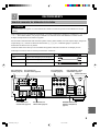
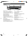
MAINS
R
L
A
B
MAIN A OR B
:
4ΩMIN. /SPEAKER
A
+
B
:
8ΩMIN. /SPEAKER
CENTER : 6ΩMIN. /SPEAKER
REAR : 6ΩMIN. /SPEAKER
MAIN A OR B
:
8ΩMIN. /SPEAKER
A
+
B
:
I6ΩMIN. /SPEAKER
CENTER : 8ΩMIN. /SPEAKER
REAR : 8ΩMIN. /SPEAKER
SET BEFORE POWER ON
REAR
(SURROUND)
CENTER
MAIN
––++
+
–
+
–
R
L
120 V 60Hz
100W MAX. TOTAL
SWITCHED
Connecting an Audio
Component (page 12)
Connecting a Video
Component (page 13)
IMPEDANCE SELECTOR
switch (page 16)
Connecting the
Antenna (page 10)
Connecting to an External
Decoder (page 12)
Connecting Speakers
(page 14)
Connecting the Power
Supply Cords (page 16)
(U.S.A. model)
V V
C C
L
R
L
R
0103V39608-18_EN 1/7/0, 2:25 PM9

10
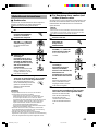
Connecting the Antennas
Both AM and FM indoor antennas are included with this unit. In general, these antennas should provide sufficient signal
strength. However, a properly installed outdoor antenna provides clearer reception than an indoor one. If you experience poor
reception quality, an outdoor antenna may improve the quality.
Connect each antenna correctly to the designated terminals.
■ Indoor FM antenna (included)
Firmly insert the connector into the FM ANT terminal. The
indoor FM antenna is only a simple antenna. For reception
with better sound quality, installing the outdoor FM antenna
(commercially available) is recommended.
Note
• Do not connect an outdoor FM antenna and the indoor FM
antenna at the same time.
■ Outdoor FM antenna
You may be unable to obtain good FM radio reception
depending on your local conditions (distance from the
broadcasting station, interposing buildings and
mountains, etc.). Consult your dealer or authorized service
center and be sure to install an antenna that suits your local
conditions.
Install the outdoor FM antenna (commercially available) in
a high place as far away from any roads as possible to avoid
being affected by automobile ignition noise.
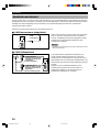
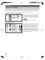
■ Connecting a coaxial cable to the included 75-ohm/300-ohm antenna
adapter (U.K. model only)
1 Open the cover of the included 75-ohm/
300-ohm antenna adapter.
2 Cut the external sleeve of the 75-ohm coaxial
cable and prepare it for connection.
3 Cut the lead wire and remove it.
4 Insert the cable wire into the slot, and clamp it
with pliers.
5 Snap the cover into place.
CONNECTIONS
75-ohm/300-ohm antenna
adapter (included for U.K.
model)
75-ohm coaxial cable
75-ohm/300-ohm antenna
adapter (included for U.K.
model)
300-ohm feeder
Unit: mm
(inch)
11 (7/16)
8 (5/16)
6 (1/14)
2
3
Lead wire
Insert the wire
into the slot.
4
Clamp with
pliers.
Clamp with
pliers.
1
Cover
5
Indoor FM
antenna
0103V39608-18_EN 1/7/0, 2:25 PM10

11
EnglishBASIC OPERATION
ADVANCED OPERA
TION APPENDIX
INTRODUCTION
PREPARATION
■ AM loop antenna (included)
The AM loop antenna can be removed from the stand and
attached to a wall, etc. However, note that the reception
sensitivity may deteriorate if the antenna is attached to a
metal or steel reinforced wall.
Notes
• The AM loop antenna should be placed away from this unit.
• The AM loop antenna should always be connected, even if an
outdoor AM antenna is connected to this unit.
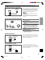
■ Connecting the AM loop antenna
1 Press the tab and unlock the terminal hole.
2 Insert the AM loop antenna lead wires into the
AM ANT and GND terminals.
3 Return the tab to its original position to lock
the lead wires. Lightly pull the lead wires to
confirm a good connection.
4 Attach the loop antenna to the antenna stand.
5 Orient the AM loop antenna so that the best
reception is obtained.
■ Outdoor AM antenna
If you cannot obtain good reception with the AM loop
antenna, connect 5 m to 10 m of vinyl covered wire to the
AM ANT terminal and extend it outdoors from a window.
■ Ground (GND terminal)
For maximum safety and minimum interference, connect
the antenna GND terminal to a good earth ground. A good
earth ground is a metal stake driven into moist earth.
CONNECTIONS
1
2
3
Antenna stand
AM loop antenna
Vinyl covered wire (5 m to 10 m)
54
0103V39608-18_EN 1/7/0, 2:25 PM11

12
Connecting an Audio Component
CONNECTIONS
Be sure to connect the right channel (R), left channel (L),
input (IN) and output (OUT) properly.
Tape deck or
MD recorder
L R L R L R
L
R
OUTPUT LINE OUT LINE IN
(U.S.A. model)
CD player
Analog signal
Signal flow
Connecting to an External Decoder
This unit has additional 6-channel audio signal input
terminals for connecting an external decoder to this unit.
Connect the 6-channel audio signal output terminals of the
decoder to the EXTERNAL DECODER INPUT terminals
of this unit.
Notes
• When a source connected to these terminals is selected, the digital
sound field processor cannot be used.
• The settings of “CENTER SP”, “REAR SP”, “MAIN SP” and
“BASS OUT” in the SET MENU have no effect on a source
connected to these terminals. The setting of “MAIN LVL” is
effective. (Refer to pages 32 and 33 for details.)
L R L R
MAIN
OUT
SURROUND
OUT
CENTER
OUT
SUBWOOFER
OUT
External decoder
(U.S.A.
model)
0103V39608-18_EN 1/7/0, 2:25 PM12

13
EnglishBASIC OPERATION
ADVANCED OPERA
TION APPENDIX
INTRODUCTION
PREPARATION
Connecting a Video Component
■ Audio signal terminals
Be sure to connect the right channel (R), left channel (L),
input (IN) and output (OUT) properly.
■ Video signal terminals
Be sure to connect the input (IN) and output (OUT)
properly.
■ Digital audio signal terminals
If your DVD/LD player, TV/digital TV or satellite
tuner, etc. has coaxial or optical digital signal output
terminals, they can be connected to this unit’s COAXIAL
and/or OPTICAL digital signal input terminals. To make a
connection between the optical digital signal terminals,
remove the cover from each terminal, and then connect
them by using a commercially available optical fiber cable
that conforms to EIA standards. Other cables might not
function correctly.
When making connections between the digital signal
terminals, you should connect the components to the same-
named analog audio signal terminals of this unit, because a
digital signal cannot be recorded by a tape deck, MD
recorder or VCR connected to this unit.
■ TV monitor with a 21-pin connector
Make a connection as shown above with a commercially
available SCART-plug connector cable.
Notes
• Be sure to attach the covers when the OPTICAL terminals are not
being used in order to protect them from dust.
• If your LD player has a Dolby Digital RF signal output terminal,
be sure to use the RF demodulator (separately purchased).
• No sound will be heard when connecting your LD player’s Dolby
Digital RF signal output terminal directly to this unit’s COAXIAL
DVD/LD digital signal input terminal.
y
• The input signal from the DVD/LD input terminals is selected in
the following order of priority with the input mode set to AUTO:
COAXIAL terminal → OPTICAL terminal → Analog terminal.
Refer to page 21 for details.
• All digital signal input terminals are applicable to sampling
frequencies of 32 kHz, 44.1 kHz and 48 kHz.
CONNECTIONS
L R
L R
L
R
C
C
V
V
L R
L R
V V
V
V
ANALOG
AUDIO OUT
AUDIO
OUT
AUDIO
IN
VIDEO
OUT
VIDEO
IN
VIDEO
IN
ANALOG
AUDIO OUT
VIDEO
OUT
VIDEO
OUT
COAXIAL
DIGITAL OUT
OPTICAL
DIGITAL OUT
OPTICAL
DIGITAL OUT
V
L
R
O
OO
DVD/LD player TV/digital TV, satellite tuner, cable TV
(U.S.A. model)
VCR
Analog signal
Video signal
Digital signal
(optical)
Digital signal
(coaxial)
Signal flow
TV monitor
SCART-plug
No connection
0103V39608-18_EN 1/7/0, 2:25 PM13

14
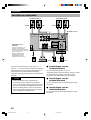
Connecting Speakers
Be sure to connect the right channel (R), left channel (L),
“+” (red) and “–” (black) properly. If the connections are
faulty, no sound will be heard from the speakers, and if the
polarity of the speaker connections is incorrect, the sound
will be unnatural and lack bass.
CAUTIONS
• Use speakers with the specified impedance shown on
the rear panel of this unit.
• Do not let the bare speaker wires touch each other and
do not let them touch any metal part of this unit. This
could damage the unit and/or speakers.
■ Main speaker terminals
One or two speaker systems can be connected to these
terminals. If you use only one speaker system, connect it to
either of the SPEAKERS A or B terminals.
■ Rear speaker terminals
A rear speaker system can be connected to these terminals.
■ Center speaker terminal
A center speaker can be connected to this terminal.
CONNECTIONS
MAINS
R
L
A
B
MAIN A OR B
:
4ΩMIN. /SPEAKER
A
+
B
:
8ΩMIN. /SPEAKER
CENTER : 6ΩMIN. /SPEAKER
REAR : 6ΩMIN. /SPEAKER
MAIN A OR B
:
8ΩMIN. /SPEAKER
A
+
B
:
I6ΩMIN. /SPEAKER
CENTER : 8ΩMIN. /SPEAKER
REAR : 8ΩMIN. /SPEAKER
SET BEFORE POWER ON
REAR
(SURROUND)
CENTER
MAIN
––++
+
–
+
–
R
L
120 V 60Hz
100W MAX. TOTAL
SWITCHED
Main speakers A
Right Left
Main speakers B
Right Left
(U.S.A. model)
Center speaker Rear speakers
Right Left
Subwoofer connection
If you have a subwoofer with built-
in amplifier, including the
YAMAHA Active Servo Processing
Subwoofer System, connect the
input terminal of the subwoofer
system to the SUBWOOFER
OUTPUT terminal of this unit.
0103V39608-18_EN 1/7/0, 2:25 PM14

15
EnglishBASIC OPERATION
ADVANCED OPERA
TION APPENDIX
INTRODUCTION
PREPARATION
■ Speaker cables
1 Remove approx. 10 mm (3/8”) of insulation
from each of the speaker cable.
2 Twist the exposed wires of the cable together
to prevent short circuits.
■ Connecting to the MAIN SPEAKERS terminals
1 Unscrew the knob.
2 Insert one bare wire into the hole in the side of
each terminal.
3 Tighten the knob to secure the wire.
■ Connecting to the REAR and CENTER SPEAKERS terminals
1 Open the tab.
2 Insert one bare wire into the hole of each
terminal.
3 Return the tab to secure the wire.
CONNECTIONS
10 mm (3/8”)
2
1
3
Red: positive (+)
Black: negative (–)
2
3
1
Red: positive (+)
Black: negative (–)
0103V39608-18_EN 1/7/0, 2:25 PM15

16
IMPEDANCE SELECTOR Switch
WARNING
Do not change the IMPEDANCE SELECTOR switch setting while the power to this unit is on, otherwise the unit may be
damaged.
If this unit fails to turn on when STANDBY/ON is pressed, the IMPEDANCE SELECTOR switch may not be fully slide
to either position. If so, slide the switch to either position fully when this unit is in the standby mode.
Select the right or left position according to the impedance of speakers in your system. Be sure to move this switch only
when this unit is in the standby mode.
Connecting the Power Supply Cords
After completing all connections, connect the AC power
cord to an AC power outlet. Disconnect the AC power cord
if you will not use this unit for a long period of time.
■ AC OUTLETS (SWITCHED)
Europe model .................................................... 2 OUTLETS
U.K. model.......................................................... 1 OUTLET
Use these outlets to connect the power cords from your
components to this unit. The power to the AC OUTLET(S)
is controlled by this unit’s STANDBY/ON (or POWER).
These outlets will supply power to any connected
component whenever this unit is turned on. The maximum
power (total power consumption of components) that can be
connected to the AC OUTLET(S) is 100 W.
If you use left position right position
Center
speaker
The impedance must be 6 Ω
or higher.
The impedance must be 8 Ω
or higher.
Rear
speakers
The impedance of each
speaker must be 6 Ω or
higher.
The impedance of each
speaker must be 8 Ω or
higher.
If you use two pairs of main
speakers, the impedance of
each speaker must be 8 Ω or
higher.
If you use two pairs of main
speakers, the impedance of
each speaker must be 16 Ω or
higher.
Main
speakers
If you use one pair of main
speakers, the impedance of
each speaker must be 4 Ω or
higher.
If you use one pair of main
speakers, the impedance of
each speaker must be 8 Ω or
higher.
CONNECTIONS
(U.S.A. model)
MAINS
MAIN A OR B
:
4ΩMIN. /SPEAKER
A
+
B
:
8ΩMIN. /SPEAKER
CENTER : 6ΩMIN. /SPEAKER
REAR : 6ΩMIN. /SPEAKER
MAIN A OR B
:
8ΩMIN. /SPEAKER
A
+
B
:
I6ΩMIN. /SPEAKER
CENTER : 8ΩMIN. /SPEAKER
REAR : 8ΩMIN. /SPEAKER
SET BEFORE POWER ON
120 V 60Hz
100W MAX. TOTAL
SWITCHED
SWITCHED
(U.S.A. model)
To AC outlet
MAINS
MAIN A OR B
:
4ΩMIN. /SPEAKER
A
+
B
:
8ΩMIN. /SPEAKER
CENTER : 6ΩMIN. /SPEAKER
REAR : 6ΩMIN. /SPEAKER
MAIN A OR B
:
8ΩMIN. /SPEAKER
A
+
B
:
I6ΩMIN. /SPEAKER
CENTER : 8ΩMIN. /SPEAKER
REAR : 8ΩMIN. /SPEAKER
SET BEFORE POWER ON
120 V 60Hz
100W MAX. TOTAL
SWITCHED
IMPEDANCE
SELECTOR
0103V39608-18_EN 1/7/0, 2:25 PM16

17
EnglishBASIC OPERATION
ADVANCED OPERA
TION APPENDIX
INTRODUCTION
PREPARATION
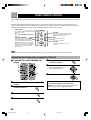
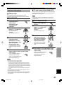
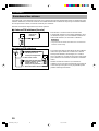
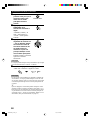
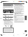
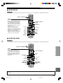
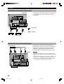
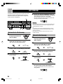
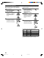
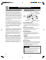
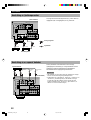
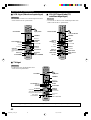
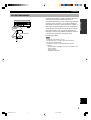
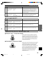
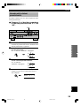
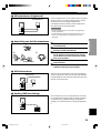
Using the Test Tone
The adjustment of each speaker sound output level should
be performed at your listening position with the remote
control. After completing the adjustments, use VOLUME
(u/d) at your listening position to check if the adjustments
are satisfactory.
1 Press AMP(TUNER) on the
component selector.
2 Press TEST.
“TEST LEFT” appears on the display.
3 Turn up the volume.
You will hear a test tone (like pink noise) from each
speaker for about two seconds in following order: left
main speaker, center speaker, right main speaker, right
rear speaker and left rear speaker. The display changes
as shown below.
Notes
• If the test tone cannot be heard, turn down the volume, set the unit
in the standby mode and check the speaker connections.
• If the test tone cannot be heard from the center speaker, check the
setting of “CENTER SP” in the SET MENU.
This procedure lets you adjust the sound output level
balance between the main, center and rear speakers by using
the built-in test tone generator. When this adjustment is
performed, the sound output level heard at the listening
position will be the same from each speaker. This is
important for the best performance of the digital sound field
processor, the Dolby Pro Logic decoder and Dolby Digital
decoder.
Before You Start Adjusting
1 Set VOLUME to the “m”
position.
2 Turn the power on.
3 Press SPEAKERS A or B
to select the main
speakers to be used.
If you use two main speaker
systems, press both A and B.
4 Set BASS, TREBLE and BALANCE to the “0”
position.
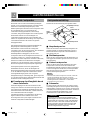
ADJUSTING THE SPEAKER BALANCE
LR
–+–+
12
4
3
LR
–+–+
1
2,7
6
3
5
TEST
LEFT
TEST
RIGHT
TEST L SUR. TEST R SUR.
TEST CENTER
0103V39608-18_EN 1/7/0, 2:25 PM17

18
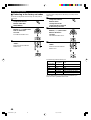
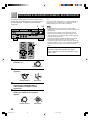
4 Adjust BALANCE on the
front panel so that the
sound output level of the
right main speaker and the
left main speaker is the
same.
5 Press TIME/LEVEL
repeatedly to select the
speaker to be adjusted.
“CENTER”, “R SUR.” or
“L SUR.” appears on the
display.
6 Press + to raise and – to
lower the level. Adjust the
sound output levels of the
center speaker and the
rear speakers so that they
become almost the same
as that of the main
speakers.
While adjusting, the test tone is
heard from the selected speaker.
Note
• You cannot adjust the delay time while the test tone is being heard
even if “DELAY” appears on the display.
7 When the adjustment is complete, press TEST.
“TEST OFF” appears on the display and the test tone
stops.
Note
• If “CENTER SP” in the SET MENU is set to the NONE position,
the sound output level of the center speaker cannot be adjusted in
step 6. The center channel sound is automatically output from the
right and left main speakers.
y
• Once you have completed the adjustments, you can only adjust
the overall volume level of your audio system by using VOLUME
(or VOLUME (u/d)).
• If there is insufficient sound output from the center and rear
speakers, you may decrease the main speaker output level by
setting “MAIN LVL” in the SET MENU to “–10 dB”. (Refer to
page 33 for details.)
ADJUSTING THE SPEAKER BALANCE
Front panel
LR
0103V39608-18_EN 1/7/0, 2:25 PM18
La pagina sta caricando ...
La pagina sta caricando ...
La pagina sta caricando ...
La pagina sta caricando ...
La pagina sta caricando ...
La pagina sta caricando ...
La pagina sta caricando ...
La pagina sta caricando ...
La pagina sta caricando ...
La pagina sta caricando ...
La pagina sta caricando ...
La pagina sta caricando ...
La pagina sta caricando ...
La pagina sta caricando ...
La pagina sta caricando ...
La pagina sta caricando ...
La pagina sta caricando ...
La pagina sta caricando ...
La pagina sta caricando ...
La pagina sta caricando ...
La pagina sta caricando ...
La pagina sta caricando ...
La pagina sta caricando ...
La pagina sta caricando ...
La pagina sta caricando ...
La pagina sta caricando ...
La pagina sta caricando ...
La pagina sta caricando ...
La pagina sta caricando ...
La pagina sta caricando ...
La pagina sta caricando ...
La pagina sta caricando ...
La pagina sta caricando ...
La pagina sta caricando ...
La pagina sta caricando ...
La pagina sta caricando ...
La pagina sta caricando ...
La pagina sta caricando ...
La pagina sta caricando ...
La pagina sta caricando ...
La pagina sta caricando ...
La pagina sta caricando ...
La pagina sta caricando ...
La pagina sta caricando ...
La pagina sta caricando ...
La pagina sta caricando ...
La pagina sta caricando ...
La pagina sta caricando ...
La pagina sta caricando ...
La pagina sta caricando ...
La pagina sta caricando ...
La pagina sta caricando ...
La pagina sta caricando ...
La pagina sta caricando ...
La pagina sta caricando ...
La pagina sta caricando ...
La pagina sta caricando ...
La pagina sta caricando ...
La pagina sta caricando ...
La pagina sta caricando ...
La pagina sta caricando ...
La pagina sta caricando ...
La pagina sta caricando ...
La pagina sta caricando ...
La pagina sta caricando ...
La pagina sta caricando ...
La pagina sta caricando ...
La pagina sta caricando ...
La pagina sta caricando ...
La pagina sta caricando ...
La pagina sta caricando ...
La pagina sta caricando ...
La pagina sta caricando ...
La pagina sta caricando ...
La pagina sta caricando ...
La pagina sta caricando ...
La pagina sta caricando ...
La pagina sta caricando ...
La pagina sta caricando ...
La pagina sta caricando ...
La pagina sta caricando ...
La pagina sta caricando ...
La pagina sta caricando ...
La pagina sta caricando ...
La pagina sta caricando ...
La pagina sta caricando ...
La pagina sta caricando ...
La pagina sta caricando ...
La pagina sta caricando ...
La pagina sta caricando ...
La pagina sta caricando ...
La pagina sta caricando ...
La pagina sta caricando ...
La pagina sta caricando ...
La pagina sta caricando ...
La pagina sta caricando ...
La pagina sta caricando ...
La pagina sta caricando ...
La pagina sta caricando ...
La pagina sta caricando ...
La pagina sta caricando ...
La pagina sta caricando ...
La pagina sta caricando ...
La pagina sta caricando ...
La pagina sta caricando ...
La pagina sta caricando ...
La pagina sta caricando ...
La pagina sta caricando ...
La pagina sta caricando ...
La pagina sta caricando ...
La pagina sta caricando ...
La pagina sta caricando ...
La pagina sta caricando ...
La pagina sta caricando ...
La pagina sta caricando ...
La pagina sta caricando ...
La pagina sta caricando ...
La pagina sta caricando ...
La pagina sta caricando ...
La pagina sta caricando ...
La pagina sta caricando ...
La pagina sta caricando ...
La pagina sta caricando ...
La pagina sta caricando ...
La pagina sta caricando ...
La pagina sta caricando ...
La pagina sta caricando ...
La pagina sta caricando ...
La pagina sta caricando ...
La pagina sta caricando ...
La pagina sta caricando ...
La pagina sta caricando ...
La pagina sta caricando ...
La pagina sta caricando ...
La pagina sta caricando ...
La pagina sta caricando ...
La pagina sta caricando ...
La pagina sta caricando ...
La pagina sta caricando ...
La pagina sta caricando ...
La pagina sta caricando ...
La pagina sta caricando ...
La pagina sta caricando ...
La pagina sta caricando ...
La pagina sta caricando ...
La pagina sta caricando ...
La pagina sta caricando ...
La pagina sta caricando ...
La pagina sta caricando ...
La pagina sta caricando ...
La pagina sta caricando ...
La pagina sta caricando ...
La pagina sta caricando ...
La pagina sta caricando ...
La pagina sta caricando ...
La pagina sta caricando ...
La pagina sta caricando ...
La pagina sta caricando ...
La pagina sta caricando ...
La pagina sta caricando ...
La pagina sta caricando ...
La pagina sta caricando ...
La pagina sta caricando ...
La pagina sta caricando ...
La pagina sta caricando ...
La pagina sta caricando ...
La pagina sta caricando ...
La pagina sta caricando ...
La pagina sta caricando ...
La pagina sta caricando ...
La pagina sta caricando ...
La pagina sta caricando ...
La pagina sta caricando ...
La pagina sta caricando ...
La pagina sta caricando ...
La pagina sta caricando ...
La pagina sta caricando ...
La pagina sta caricando ...
La pagina sta caricando ...
La pagina sta caricando ...
La pagina sta caricando ...
La pagina sta caricando ...
La pagina sta caricando ...
La pagina sta caricando ...
La pagina sta caricando ...
La pagina sta caricando ...
La pagina sta caricando ...
La pagina sta caricando ...
La pagina sta caricando ...
La pagina sta caricando ...
La pagina sta caricando ...
La pagina sta caricando ...
La pagina sta caricando ...
La pagina sta caricando ...
La pagina sta caricando ...
La pagina sta caricando ...
La pagina sta caricando ...
La pagina sta caricando ...
La pagina sta caricando ...
La pagina sta caricando ...
La pagina sta caricando ...
La pagina sta caricando ...
La pagina sta caricando ...
La pagina sta caricando ...
La pagina sta caricando ...
La pagina sta caricando ...
La pagina sta caricando ...
La pagina sta caricando ...
La pagina sta caricando ...
La pagina sta caricando ...
La pagina sta caricando ...
La pagina sta caricando ...
La pagina sta caricando ...
La pagina sta caricando ...
La pagina sta caricando ...
La pagina sta caricando ...
La pagina sta caricando ...
La pagina sta caricando ...
La pagina sta caricando ...
La pagina sta caricando ...
La pagina sta caricando ...
La pagina sta caricando ...
La pagina sta caricando ...
La pagina sta caricando ...
La pagina sta caricando ...
La pagina sta caricando ...
La pagina sta caricando ...
La pagina sta caricando ...
La pagina sta caricando ...
La pagina sta caricando ...
La pagina sta caricando ...
La pagina sta caricando ...
La pagina sta caricando ...
La pagina sta caricando ...
La pagina sta caricando ...
La pagina sta caricando ...
La pagina sta caricando ...
La pagina sta caricando ...
La pagina sta caricando ...
La pagina sta caricando ...
La pagina sta caricando ...
La pagina sta caricando ...
La pagina sta caricando ...
La pagina sta caricando ...
La pagina sta caricando ...
La pagina sta caricando ...
La pagina sta caricando ...
La pagina sta caricando ...
La pagina sta caricando ...
La pagina sta caricando ...
La pagina sta caricando ...
La pagina sta caricando ...
La pagina sta caricando ...
La pagina sta caricando ...
La pagina sta caricando ...
La pagina sta caricando ...
La pagina sta caricando ...
La pagina sta caricando ...
La pagina sta caricando ...
La pagina sta caricando ...
La pagina sta caricando ...
La pagina sta caricando ...
La pagina sta caricando ...
La pagina sta caricando ...
La pagina sta caricando ...
La pagina sta caricando ...
La pagina sta caricando ...
La pagina sta caricando ...
La pagina sta caricando ...
La pagina sta caricando ...
La pagina sta caricando ...
La pagina sta caricando ...
La pagina sta caricando ...
La pagina sta caricando ...
La pagina sta caricando ...
La pagina sta caricando ...
La pagina sta caricando ...
La pagina sta caricando ...
La pagina sta caricando ...
La pagina sta caricando ...
La pagina sta caricando ...
La pagina sta caricando ...
La pagina sta caricando ...
La pagina sta caricando ...
La pagina sta caricando ...
La pagina sta caricando ...
La pagina sta caricando ...
La pagina sta caricando ...
La pagina sta caricando ...
La pagina sta caricando ...
La pagina sta caricando ...
La pagina sta caricando ...
La pagina sta caricando ...
La pagina sta caricando ...
La pagina sta caricando ...
La pagina sta caricando ...
La pagina sta caricando ...
La pagina sta caricando ...
La pagina sta caricando ...
La pagina sta caricando ...
La pagina sta caricando ...
La pagina sta caricando ...
La pagina sta caricando ...
La pagina sta caricando ...
La pagina sta caricando ...
La pagina sta caricando ...
La pagina sta caricando ...
La pagina sta caricando ...
La pagina sta caricando ...
La pagina sta caricando ...
La pagina sta caricando ...
La pagina sta caricando ...
La pagina sta caricando ...
La pagina sta caricando ...
La pagina sta caricando ...
La pagina sta caricando ...
La pagina sta caricando ...
La pagina sta caricando ...
La pagina sta caricando ...
La pagina sta caricando ...
La pagina sta caricando ...
La pagina sta caricando ...
La pagina sta caricando ...
La pagina sta caricando ...
La pagina sta caricando ...
La pagina sta caricando ...
La pagina sta caricando ...
La pagina sta caricando ...
La pagina sta caricando ...
La pagina sta caricando ...
La pagina sta caricando ...
La pagina sta caricando ...
La pagina sta caricando ...
La pagina sta caricando ...
La pagina sta caricando ...
La pagina sta caricando ...
La pagina sta caricando ...
La pagina sta caricando ...
La pagina sta caricando ...
La pagina sta caricando ...
La pagina sta caricando ...
La pagina sta caricando ...
La pagina sta caricando ...
La pagina sta caricando ...
La pagina sta caricando ...
La pagina sta caricando ...
La pagina sta caricando ...
La pagina sta caricando ...
-
 1
1
-
 2
2
-
 3
3
-
 4
4
-
 5
5
-
 6
6
-
 7
7
-
 8
8
-
 9
9
-
 10
10
-
 11
11
-
 12
12
-
 13
13
-
 14
14
-
 15
15
-
 16
16
-
 17
17
-
 18
18
-
 19
19
-
 20
20
-
 21
21
-
 22
22
-
 23
23
-
 24
24
-
 25
25
-
 26
26
-
 27
27
-
 28
28
-
 29
29
-
 30
30
-
 31
31
-
 32
32
-
 33
33
-
 34
34
-
 35
35
-
 36
36
-
 37
37
-
 38
38
-
 39
39
-
 40
40
-
 41
41
-
 42
42
-
 43
43
-
 44
44
-
 45
45
-
 46
46
-
 47
47
-
 48
48
-
 49
49
-
 50
50
-
 51
51
-
 52
52
-
 53
53
-
 54
54
-
 55
55
-
 56
56
-
 57
57
-
 58
58
-
 59
59
-
 60
60
-
 61
61
-
 62
62
-
 63
63
-
 64
64
-
 65
65
-
 66
66
-
 67
67
-
 68
68
-
 69
69
-
 70
70
-
 71
71
-
 72
72
-
 73
73
-
 74
74
-
 75
75
-
 76
76
-
 77
77
-
 78
78
-
 79
79
-
 80
80
-
 81
81
-
 82
82
-
 83
83
-
 84
84
-
 85
85
-
 86
86
-
 87
87
-
 88
88
-
 89
89
-
 90
90
-
 91
91
-
 92
92
-
 93
93
-
 94
94
-
 95
95
-
 96
96
-
 97
97
-
 98
98
-
 99
99
-
 100
100
-
 101
101
-
 102
102
-
 103
103
-
 104
104
-
 105
105
-
 106
106
-
 107
107
-
 108
108
-
 109
109
-
 110
110
-
 111
111
-
 112
112
-
 113
113
-
 114
114
-
 115
115
-
 116
116
-
 117
117
-
 118
118
-
 119
119
-
 120
120
-
 121
121
-
 122
122
-
 123
123
-
 124
124
-
 125
125
-
 126
126
-
 127
127
-
 128
128
-
 129
129
-
 130
130
-
 131
131
-
 132
132
-
 133
133
-
 134
134
-
 135
135
-
 136
136
-
 137
137
-
 138
138
-
 139
139
-
 140
140
-
 141
141
-
 142
142
-
 143
143
-
 144
144
-
 145
145
-
 146
146
-
 147
147
-
 148
148
-
 149
149
-
 150
150
-
 151
151
-
 152
152
-
 153
153
-
 154
154
-
 155
155
-
 156
156
-
 157
157
-
 158
158
-
 159
159
-
 160
160
-
 161
161
-
 162
162
-
 163
163
-
 164
164
-
 165
165
-
 166
166
-
 167
167
-
 168
168
-
 169
169
-
 170
170
-
 171
171
-
 172
172
-
 173
173
-
 174
174
-
 175
175
-
 176
176
-
 177
177
-
 178
178
-
 179
179
-
 180
180
-
 181
181
-
 182
182
-
 183
183
-
 184
184
-
 185
185
-
 186
186
-
 187
187
-
 188
188
-
 189
189
-
 190
190
-
 191
191
-
 192
192
-
 193
193
-
 194
194
-
 195
195
-
 196
196
-
 197
197
-
 198
198
-
 199
199
-
 200
200
-
 201
201
-
 202
202
-
 203
203
-
 204
204
-
 205
205
-
 206
206
-
 207
207
-
 208
208
-
 209
209
-
 210
210
-
 211
211
-
 212
212
-
 213
213
-
 214
214
-
 215
215
-
 216
216
-
 217
217
-
 218
218
-
 219
219
-
 220
220
-
 221
221
-
 222
222
-
 223
223
-
 224
224
-
 225
225
-
 226
226
-
 227
227
-
 228
228
-
 229
229
-
 230
230
-
 231
231
-
 232
232
-
 233
233
-
 234
234
-
 235
235
-
 236
236
-
 237
237
-
 238
238
-
 239
239
-
 240
240
-
 241
241
-
 242
242
-
 243
243
-
 244
244
-
 245
245
-
 246
246
-
 247
247
-
 248
248
-
 249
249
-
 250
250
-
 251
251
-
 252
252
-
 253
253
-
 254
254
-
 255
255
-
 256
256
-
 257
257
-
 258
258
-
 259
259
-
 260
260
-
 261
261
-
 262
262
-
 263
263
-
 264
264
-
 265
265
-
 266
266
-
 267
267
-
 268
268
-
 269
269
-
 270
270
-
 271
271
-
 272
272
-
 273
273
-
 274
274
-
 275
275
-
 276
276
-
 277
277
-
 278
278
-
 279
279
-
 280
280
-
 281
281
-
 282
282
-
 283
283
-
 284
284
-
 285
285
-
 286
286
-
 287
287
-
 288
288
-
 289
289
-
 290
290
-
 291
291
-
 292
292
-
 293
293
-
 294
294
-
 295
295
-
 296
296
-
 297
297
-
 298
298
-
 299
299
-
 300
300
-
 301
301
-
 302
302
-
 303
303
-
 304
304
-
 305
305
-
 306
306
-
 307
307
-
 308
308
-
 309
309
-
 310
310
-
 311
311
-
 312
312
-
 313
313
-
 314
314
-
 315
315
-
 316
316
-
 317
317
-
 318
318
-
 319
319
-
 320
320
-
 321
321
-
 322
322
-
 323
323
-
 324
324
-
 325
325
-
 326
326
-
 327
327
-
 328
328
-
 329
329
-
 330
330
-
 331
331
-
 332
332
-
 333
333
-
 334
334
-
 335
335
-
 336
336
-
 337
337
-
 338
338
-
 339
339
-
 340
340
-
 341
341
-
 342
342
-
 343
343
-
 344
344
-
 345
345
-
 346
346
-
 347
347
-
 348
348
-
 349
349
-
 350
350
-
 351
351
-
 352
352
-
 353
353
-
 354
354
-
 355
355
-
 356
356
-
 357
357
-
 358
358
-
 359
359
-
 360
360
-
 361
361
-
 362
362
-
 363
363
-
 364
364
-
 365
365
-
 366
366
-
 367
367
-
 368
368


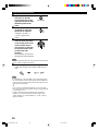
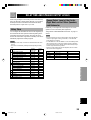
Yamaha RX-V396 Manuale del proprietario
- Categoria
- Lettori minidisc
- Tipo
- Manuale del proprietario
in altre lingue
- English: Yamaha RX-V396 Owner's manual
- français: Yamaha RX-V396 Le manuel du propriétaire
- español: Yamaha RX-V396 El manual del propietario
- Deutsch: Yamaha RX-V396 Bedienungsanleitung
- Nederlands: Yamaha RX-V396 de handleiding
- svenska: Yamaha RX-V396 Bruksanvisning