Rockford Fosgate Power Elite T3002 Guida d'installazione
- Categoria
- Altoparlanti
- Tipo
- Guida d'installazione
Questo manuale è adatto anche per

Installation &
Operation
Installation et fonctionnement
Instalación y funcionamiento
Einbau und Betrieb
Installazione e funzionamento
2-CHANNEL AND
4-CHANNEL AMPLIFIERS
T3002
T4004

INTRODUCTION
TABLE OF CONTENTS
2
Dear Customer,
Congratulations on your purchase of the world's finest brand of car audio amplifiers.At Rockford Fosgate we are
fanatics about musical reproduction at its best, and we are pleased you chose our product.Through years of
engineering expertise, hand craftsmanship and critical testing procedures, we have created a wide range of
products that reproduce music with all the clarity and richness you deserve.
For maximum performance we recommend you have your new Rockford Fosgate product installed by an
Authorized Rockford Fosgate Dealer, as we provide specialized training through Rockford Technical Training Institute
(RTTI). Please read your warranty and retain your receipt and original carton for possible future use.
Great product and competent installations are only a piece of the puzzle when it comes to your system. Make sure
that your installer is using 100% authentic installation accessories from Connecting Punch in your installation.
Connecting Punch has everything from RCA cables and speaker wire to Power line and battery connectors. Insist on
it! After all, your new system deserves nothing but the best.
To add the finishing touch to your new Rockford Fosgate image order your Rockford accessories, which include
everything from T-shirts to jackets and hats.
To get a free brochure on Rockford Fosgate products and Rockford accessories,
visit our web site at: www.rockfordfosgate.com
or, in the U.S. call 1-800-669-9899 or FAX 1-800-398-3985.
For all other countries, call +001-480-967-3565 or FAX +001-480-967-8132.
PRACTICE SAFE SOUND™
Continuous exposure to sound pressure levels over 100dB may cause permanent
hearing loss. High powered auto sound systems may produce sound pressure levels well
over 130dB. Use common sense and practice safe sound.
Introduction. . . . . . . . . . . . . . . . . . . . . . . . . 2
Safety Instructions . . . . . . . . . . . . . . . . . . . 3
Design Features. . . . . . . . . . . . . . . . . . . . . . 4
Installation . . . . . . . . . . . . . . . . . . . . . . . 5-10
Installation Considerations . . . . . . . . . . . . . . 5
Mounting Locations. . . . . . . . . . . . . . . . . . . . 5
Battery and Charging . . . . . . . . . . . . . . . . . . 6
Wiring the System. . . . . . . . . . . . . . . . . . . . . 6
NOTE:Review each section for more detailed information.
If, after reading your manual, you still have questions regarding this product, we recommend that you see
your Rockford Fosgate dealer. If you need further assistance, you can call us direct at
1-800-669-9899. Be sure to have your serial number, model number and date of purchase available when
you call.
The serial number can be found on the outside of the box. Please record it in the space provided below as
your permanent record.This will serve as verification of your factory warranty and may become useful in
recovering your unit if it is ever stolen.
Serial Number: ______________________________________
Model Number: _____________________________________
Operation . . . . . . . . . . . . . . . . . . . . . . . 11-12
Para-Punch Remote Bass . . . . . . . . . . . . . . 11
Adjusting Gain . . . . . . . . . . . . . . . . . . . . . . . 12
Adjusting Crossover Frequency . . . . . . . . . 12
Troubleshooting. . . . . . . . . . . . . . . . . . . . . 13
Specifications. . . . . . . . . . . . . . . . . . . . . . . 14
Limited Warranty Information . . . . . . . . 15

SAFETY INSTRUCTIONS
CONTENTS OF CARTON
3
Visit our web site for the latest information on all Rockford products.
GETTING STARTED
Welcome to Rockford Fosgate! This manual is designed to provide information for the owner,
salesperson and installer. For those of you who want quick information on how to install this product,
please turn to the Installation Section of this manual. Other information can be located by using the
Table of Contents.We, at Rockford Fosgate, have worked very hard to make sure all the information in
this manual is current. But, as we are constantly finding new ways to improve our product, this
information is subject to change without notice.
www.rockfordfosgate.com
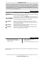
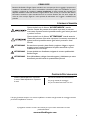
This symbol with “WARNING” is intended to alert the user to the
presence of important instructions. Failure to heed the instructions
will result in severe injury or death.
This symbol with “CAUTION” is intended to alert the user to the
presence of important instructions. Failure to heed the instructions
can result in injury or unit damage.
CAUTION:To prevent injury and damage to the unit, please read and follow the
instructions in this manual.We want you to enjoy this system, not get a
headache.
CAUTION If you feel unsure about installing this system yourself, have it installed by a
qualified Rockford Fosgate technician.
CAUTION Before installation, disconnect the battery negative (-) terminal to prevent
damage to the unit, fire and/or possible injury.
Either a Power T3002 2-Channel Amplifier, or
a Power T4004 4-Channel Amplifier
Installation & Operation Manual
Mounting Hardware Kit
Para-Punch Remote Bass Kit with Cord
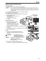
The hardware kit included with each amplifier contains the mounting hardware necessary to secure the
amplifier to the vehicle.

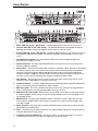
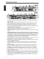
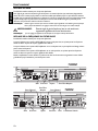
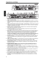
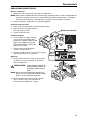
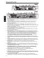
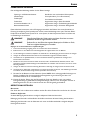
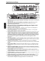
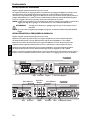
1. Power LED (Top of unit - Not Shown) – This Blue LED illuminates when the unit is turned on.
2. Thermal LED (Top of unit - Not Shown) – This Red LED illuminates if the amplifier reaches the
third stage of thermal protection.The amplifier will shut down to cool if this occurs.
3. Protect LED (Top of unit - Not Shown) – This Yellow LED illuminates if a short circuit or too low of
an impedance is detected at the speaker connections.The amplifier will automatically shut down if this
occurs.
4. Cast Aluminum Heatsink – The cast aluminum heatsink of the Power amplifier dissipates heat
generated by the amplifier's circuitry.
5. Speaker Terminals – The heavy duty, nickel-plated clamp wire connectors (
+
and -) will accept wire
sizes from 8 AWG to 18 AWG.
6. Remote Bass – The Para-Punch Remote Bass connection is made with a RJ-45 cable and can be installed
in a variety of ways for easy control access. One control is used to boost low frequency information to
overcome road noise and put the bass in your face.This Bass control is a narrow band adjustment
variable from 0dB to +18dB with a Gyrator based Punch EQ that eliminates frequency shift with boost.
The other control is used for adjusting center frequency variable from 35Hz to 70Hz.
7. Gain Control – The input gain control is preset to match the output of most source units. It can be
adjusted to match output levels from a variety of source units.
8. Variable Crossover – Is a built-in 12dB/octave Butterworth filter selectable for High-Pass (HP),All Pass
(AP), or Low-Pass (LP) operation variable from 40Hz to 400Hz.
9. RCA Input Jacks – The industry standard RCA jacks provide an easy connection for signal level input.
They are nickel-plated to resist the signal degradation caused by corrosion.
10. RCA Active Pass-Thru Jacks – This Active Pass-Thru provides a convenient source for daisy-chaining
an additional amplifier without running an extra set of RCA cables from the front of the vehicle to the
rear amplifier location.
11. REM Terminal – The heavy duty, nickel-plated captive c-clamp wire connector will accept wire sizes
from 12 AWG to 24 AWG.This terminal is used to remotely turn-on and turn-off the amplifier when
+12V DC is applied.
12. Power Terminals – The power and ground are nickel-plated captive c-clamp wire connectors and will
accommodate up to 4 AWG wire.
13. Fuses – These ATC fuses are easily accessible in case of failure.Always replace fuses with same type and
rating. See Specifications for fuse ratings.
14. 2/4 Channel Switch (T4004 only) – Pressing this switch in, switches the inputs to a 2-channel
mode, allowing connection to only the front inputs with a 4-channel output.
4
DESIGN FEATURES

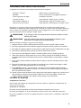
5
INSTALLA
TION
INSTALLATION CONSIDERATIONS
The following is a list of tools needed for installation:
Volt/Ohm Meter
Wire strippers
Wire crimpers
Wire cutters
#2 Phillips screwdriver
Battery post wrench
Hand held drill w/assorted bits
1/8" diameter heatshrink tubing
Assorted connectors
Adequate Length—Red Power Wire
Adequate Length—Remote Turn-on Wire
Adequate Length—Black Grounding Wire
This section focuses on some of the vehicle considerations for installing your new amplifier.
Pre-planning your system layout and best wiring routes will save installation time.When deciding on the
layout of your new system, be sure that each component will be easily accessible for making adjustments.
CAUTION:If you feel unsure about installing this system yourself, have it installed by a
qualified technician.
CAUTION:Before installation, disconnect the battery negative (-) terminal to prevent
damage to the unit, fire and/or possible injury.
Before beginning any installation, follow these simple rules:
1. Be sure to carefully read and understand the instructions before attempting to install the unit.
2. For safety, disconnect the negative lead from the battery prior to beginning the installation.
3. For easier assembly, we suggest you run all wires prior to mounting your unit in place.
4. Route all of the RCA cables close together and away from any high current wires.
5. Use high quality connectors for a reliable installation and to minimize signal or power loss.
6. Think before you drill! Be careful not to cut or drill into gas tanks, fuel lines, brake or hydraulic lines,
vacuum lines or electrical wiring when working on any vehicle.
7. Never run wires underneath the vehicle. Running the wires inside the vehicle provides the best
protection.
8. Avoid running wires over or through sharp edges. Use rubber or plastic grommets to protect any
wires routed through metal, especially the firewall.
9. ALWAYS protect the battery and electrical system from damage with proper fusing. Install the
appropriate fuse holder and fuse on the +12V power wire within 18" (45.7 cm) of the battery
terminal.
10. When grounding to the chassis of the vehicle, scrape all paint from the metal to ensure a good, clean
ground connection. Grounding connections should be as short as possible and always be connected to
metal that is welded to the main body, or chassis, of the vehicle.
MOUNTING LOCATIONS
Engine Compartment
Never mount this unit in the engine compartment. Mounting the unit in the engine compartment will void
your warranty.
Trunk Mounting
Mounting the amplifier vertically will provide adequate cooling of the amplifier.
Mounting the amplifier on the floor of the trunk will provide the best cooling of the amplifier.
Mounting the amplifier upside down to the rear deck of the trunk will not provide proper cooling and will
severely affect the performance of the amplifier and is strongly not recommended.

6
INSTALLA
TION
Passenger Compartment Mounting
Mounting the amplifier in the passenger compartment will work as long as you provide a sufficient amount
of air for the amplifier to cool itself. If you are going to mount the amplifier under the seat of the vehicle,
you must have at least 1" (2.54cm) of air gap around the amplifier's heatsink.
Mounting the amplifier with less than 1" (2.54cm) of air gap around the amplifier's heatsink in the
passenger compartment will not provide proper cooling and will severely affect the performance of the
amplifier and is strongly not recommended.
BATTERY AND CHARGING
Amplifiers will put an increased load on the vehicle's battery and charging system.We recommend
checking your alternator and battery condition to ensure that the electrical system has enough capacity to
handle the increased load of your stereo system. Stock electrical systems which are in good condition
should be able to handle the extra load of any Power Series amplifier without problems, although battery
and alternator life can be reduced slightly.To maximize the performance of your amplifier, we suggest the
use of a heavy duty battery and an energy storage capacitor.
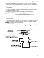
WIRING THE SYSTEM
CAUTION:If you do not feel comfortable with wiring your new unit, please see your
local Authorized Rockford Fosgate Dealer for installation.
CAUTION:Before installation, disconnect the battery negative (-) terminal to prevent
damage to the unit, fire and/or possible injury.
CAUTION:Avoid running power wires near the low level input cables, antenna, power
leads, sensitive equipment or harnesses.The power wires carry substantial
current and could induce noise into the audio system.
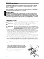
1. Plan the wire routing. Keep RCA cables close together but isolated from the amplifier's power cables
and any high power auto accessories, especially electric motors.This is done to prevent coupling the
noise from radiated electrical fields into the audio signal.When feeding the wires through the firewall
or any metal barrier, protect them with plastic or rubber grommets to prevent short circuits. Leave
the wires long at this point to adjust for a precise fit at a later time.
2. Prepare the RED wire (power cable) for attachment to the amplifier by stripping 5/8" of insulation
from the end of the wire. Insert the bared wire into the B+ terminal and tighten the set screw to
secure the cable in place.
NOTE:The B+ cable MUST be fused 18" or less from the vehicle's battery. Install the fuseholder under
the hood and ensure connections are water tight.
3. Trim the RED wire (power cable) within 18" of the battery and splice in a inline fuse holder. See
Specifications for the rating of the fuse to be used. DO NOT install the fuse at this time.
4. Strip 1/2" from the battery end of the power cable and crimp a large ring terminal to the cable. Use
the ring terminal to connect to the battery positive terminal.
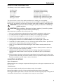
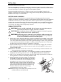
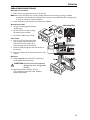
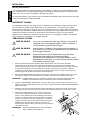
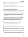
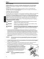
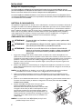
5. Prepare the BLACK wire (Ground cable) for attachment to
the amplifier by stripping 5/8" of insulation from the end of
the wire. Insert the bare wire into the GROUND terminal
and tighten the set screw to secure the cable in place.
Prepare the chassis ground by scraping any paint from the
metal surface and thoroughly clean the area of all dirt and
grease. Strip the other end of the wire and attach a ring
connector. Fasten the cable to the chassis using a
non-anodized screw and a star washer.
NOTE:Keep the length of the BLACK wire (Ground) as short as
possible.Always less than 30"(76.2cm).

7
INSTALLA
TION
6. Prepare the Remote turn-on wire for for attachment to the amplifier by stripping 5/8" of insulation
from the end of the wire. Insert the bared wire into the REMOTE terminal and tighten the set screw
to secure the wire in place. Connect the other end of the Remote wire to a switched 12 volt positive
source.The switched voltage is usually taken from the source unit's remote amp on lead. If the source
unit does not have this output available, the recommended solution is to wire a mechanical switch in
line with a 12 volt source to activate the amplifier.
7. Securely mount the amplifier to the vehicle or amp rack. Be careful not to mount the amplifier on
cardboard or plastic panels. Doing so may enable the screws to pull out from the panel due to road
vibration or sudden vehicle stops.
8. Connect from source signal by plugging the RCA cables into the input jacks at the amplifier.
CAUTION:Always ensure power is off or disconnected at the amplifier before
connecting RCA cables. Failure to do so may cause injury, damage to the
amplifier and/or connected components.
9. Connect the speakers. Strip the speaker wires 1/2" and insert into the speaker terminal and tighten
the set screw to secure into place. Be sure to maintain proper speaker polarity. DO NOT chassis
ground any of the speaker leads as unstable operation may result.
10. Perform a final check of the completed system wiring to ensure that all connections are accurate.
Check all power and ground connections for frayed wires and loose connections which could cause
problems. Install inline fuse near battery connection.
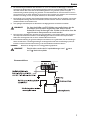
NOTE:Follow the diagrams for proper signal polarity.
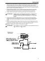
CAUTION:These amplifiers are not recommended for impedance loads below 1
stereo and 2 bridged.
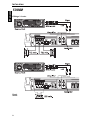
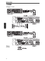
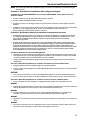
Power
Connection

8
INSTALLA
TION
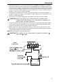
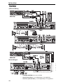
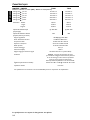
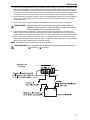
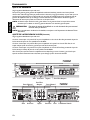
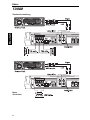
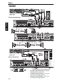
2-Channel Wiring
Bridged/Mono Wiring
T3002

9
INSTALLA
TION
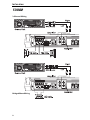
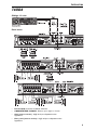
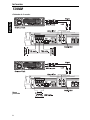
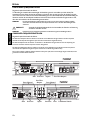
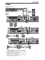
2-Channel Wiring
Mono Bridged
• RCA Inputs connect to FRONT inputs only.
• 2/4 CHN. SWITCH push in to set to 2 CHN.
• Gain (Front & Rear) - is set independently to suit application.
• Crossover (Front & Rear) - is set independently to suit application.
T4004

10
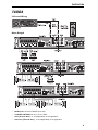
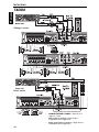
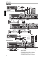
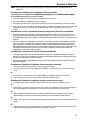
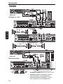
Stereo Bridged
• 2/4 CHN. SWITCH out to set to 4 CHN.
• Gain (Front & Rear) - is set independently to suit application.
• Crossover (Front & Rear) - is set independently to suit application.
INSTALLA
TION
T4004
4-Channel Wiring

11
OPERATION
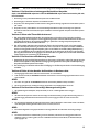
PARA-PUNCH REMOTE BASS
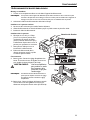
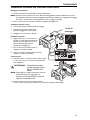
Mounting and installation
1. Find a location that gives easy access to the remote.
NOTE:You can mount this unit in a variety of ways. Remove the back housing by using a small flat
screwdriver in the slotted hole at the back.The housing can be installed with the mounting tab up
or down, or left off for in panel installation.
2. Route the cable for the remote and connect to the amplifier.
Outside Panel Install
3. Using the screws supplied, install the
mounting clip.
4. Slip the remote onto the mounting
clip until it snaps into place.
5. Connect the cable to the remote.
Panel Install
6. Cut out a 2”x 7/8” hole in the panel,
with a maximum panel thickness of
3/8”. Ensure there is enough room
within the panel area for connection.
7. Route the cable through the hole and connect to
the remote.
8. Press the remote into the panel cutout until it clicks
in place.
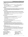
Operation
9. Left Knob-Bass Boost Control:Turn clockwise to
boost amplifier bass frequencies.
CAUTION:Overexcursion and subsequent
damage may occur at high levels
of boost
10. Right Knob-Center Frequency Control:
Turn clockwise to select the center frequency
desired (35Hz-70Hz).
20 30 40 50 70 90 200
+18
+14
+10
+6
+2
0
-2
dB
Hz
Mounting Clip

12
ADJUSTING GAIN
Do the following individually for each channel.
To adjust the gain setting, turn the amplifier gains all the way down (counter-clockwise).Turn the source unit
volume up until distortion is audible and then turn it down a bit until the distortion is inaudible.This will be
about all the way up on most source units. Next, increase the amplifier gain setting until adequate volume is
achieved. Rockford Fosgate source units do not distort, so the volume can be used at maximum setting.
NOTE:Best signal to noise and dynamic range are realized with the gain at minimum. Most users find
adequate gain and volume is achieved at about halfway in the adjustment range.
CAUTION:Avoid setting the amplifier gain very high as noise and distortion will
increase significantly.
NOTE:For a more in depth setting procedure, contact Rockford Technical Support.
ADJUSTING CROSSOVER FREQUENCY
Do the following individually for each channel.
Placing the switch in the HP position sets the amplifier to the High Pass mode, enabling frequencies above
the cut-off point to pass, adjustable between 40-400Hz.
Placing the switch in the AP position sets the amplifier to the All Pass mode, preventing any crossover
adjustment, allowing all frequencies to pass.
Placing the switch in the LP position sets the amplifier to the Low Pass mode, enabling frequencies below
the cut-off point to pass, adjustable between 40-400Hz.
Turn the crossover adjustment knob all the way down.With the system playing, turn the crossover
adjustment knob up slowly until the desired crossover point is achieved.
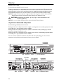
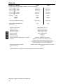
Gain Crossover Inputs
Inputs
Front Channel
2/4-Channel Switch
Pass-Thru
Outputs
Rear Channel
Gain
Gain Crossover
Crossover
Pass-Thru Outputs
T4004
T3002
OPERATION

13
TROUBLESHOO
TING
NOTE:If you are having problems after installation follow the Troubleshooting procedures below.
Procedure 1: Check Amplifier for proper connections.
Verify that POWER light is on. If POWER light is on skip to Step 3, if not continue.
1. Check in-line fuse on battery positive cable. Replace if necessary.
2. Check fuse(s) on amplifier. Replace if necessary.
3. Verify that Ground connection is connected to clean metal on the vehicle’s chassis. Repair/replace if
necessary.
4. Verify there is 10.5 - 15.5 Volts present at the positive battery and remote turn-on cable.Verify quality
connections for both cables at amplifier, stereo, and battery/fuseholder. Repair/replace if necessary.
Procedure 2: Protect or Thermal light is on.
1. If the Protect light is on, this is a sign of a possible short in the speaker connections. Check for
proper speaker connections and use an ohm meter to check for possible shorts in the speaker wiring.
Too low of a speaker impedance may also cause Protect to light.
2. If the Thermal light is on, this is usually a sign of driving the amplifier at very high power levels without
adequate airflow around the amplifier. Shut off the system and allow to cool. Check for proper
speaker impedance, rewire if needed. Low battery voltage may also cause Thermal to light. Check that
the vehicle charging system is maintaining proper voltage. If the previous items do not solve the
problem, a fault may be in the amplifier, call customer service for support.
Procedure 3: Check Amplifier for audio output.
1. Verify good RCA input connections at stereo and amplifier. Check entire length of cables for kinks,
splices, etc.Test RCA inputs for AC volts with stereo on. Repair/replace if necessary.
2. Disconnect RCA input from amplifier. Connect RCA input from test stereo directly to amplifier input.
Procedure 4: Check Amplifier if you experience Turn-on Pop.
1. Disconnect input signal to amplifier and turn amplifier on and off.
2. If the noise is eliminated, connect the REMOTE lead of amplifier to source unit with a delay turn-on
module.
OR
1. Use a different 12 Volt source for REMOTE lead of amplifier (i.e. battery direct).
2. If the noise is eliminated, use a relay to isolate the amplifier from noisy turn-on output.
Procedure 5: Check Amplifier if you experience excess Engine Noise.
1. Route all signal carrying wires (RCA, Speaker cables) away from power and ground wires.
OR
2. Bypass any and all electrical components between the stereo and the amplifier(s). Connect stereo
directly to input of amplifier. If noise goes away the unit being bypassed is the cause of the noise.
OR
3. Remove existing ground wires for all electrical components. Reground wires to different locations.
Verify that grounding location is clean, shiny metal free of paint, rust etc.
OR
4. Add secondary ground cable from negative battery terminal to the chassis metal or engine block of
vehicle.
OR
5. Have alternator and battery load tested by your mechanic.Verify good working order of vehicle
electrical system including distributor, spark plugs, spark plug wires, voltage regulator etc.

14
SPECIFICATIONS
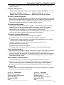
MODEL- POWER T3002 T4004
Continuous Power Rating (RMS) - Measured at 14.4 Battery Volts
4 Load Per Channel 50 Watts x 2 25 Watts x 4
2 Load Per Channel 100 Watts x 2 50 Watts x 4
1 Load Per Channel 150 Watts x 2 100 Watts x 4
4 Load Bridged 200 Watts x 1 100 Watts x 2
2 Load Bridged 300 Watts x 1 200 Watts x 2
Dimensions: Height 2.3" (5.80cm) 2.3" (5.80cm)
Width 12.9" (32.70cm) 12.9" (32.70cm)
Length 11.8" (30.00cm) 16.3" (41.50cm)
Amplifier Fuse Rating (Amp/Type) (2) 40A / ATC (2) 40A / ATC
Battery Fuse Rating (Amp) External 80A 80A
(Not Supplied)
Signal-to-Noise Ratio >80dB A-weighted @ 2Vrms
Crossover Slope 12dB/octave Butterworth
Crossover Frequency variable from 40Hz to 400Hz
Frequency Response 20Hz to 20kHz ±0.5dB
Bandwidth 20Hz to 200kHz ±3dB
Slew Rate 30 Volts/µS
IM Distortion (IHF) <0.05%
Signal Voltage Adjustment Range Variable from 150mV to 4V (RCA Input)
Protection NOMAD - Internal analog-computer output protection circuitry
limits power in case of overload, plus short protection.
Thermal switch shuts down the amplifier in case of overheating.
Equalization (Variable Punch Bass) Variable from 0dB to +18dB @ variable 35 to 70Hz
Input Impedance 10k ohms
These specifications are Amplifier Power Standard CEA-2006 Compliant
Specifications subject to change without notice

15
LIMITED WARRANTY INFORMATION
Rockford Corporation offers a limited warranty on Rockford Fosgate products on the
following terms:
Length of Warranty
Source Units, Speakers, Signal Processors and PUNCH Amplifiers – 1 Year
POWER Amplifiers – 2 Years Type RF Amplifiers – 3 Years
Any Factory Refurbished Product – 90 days (receipt required)
What is Covered
This warranty applies only to Rockford Fosgate products sold to consumers by Authorized
Rockford Fosgate Dealers in the United States of America or its possessions. Product
purchased by consumers from an Authorized Rockford Fosgate Dealer in another country are
covered only by that country’s Distributor and not by Rockford Corporation.
Who is Covered
This warranty covers only the original purchaser of Rockford product purchased from an
Authorized Rockford Fosgate Dealer in the United States. In order to receive service, the
purchaser must provide Rockford with a copy of the receipt stating the customer name, dealer
name, product purchased and date of purchase.
Products found to be defective during the warranty period will be repaired or replaced
(with a product deemed to be equivalent) at Rockford's discretion.
What is Not Covered
1. Damage caused by accident, abuse, improper operations, water, theft, shipping
2.Any cost or expense related to the removal or reinstallation of product
3. Service performed by anyone other than Rockford or an Authorized Rockford Fosgate
Service Center
4.Any product which has had the serial number defaced, altered, or removed
5. Subsequent damage to other components
6.Any product purchased outside the U.S.
7.Any product not purchased from an Authorized Rockford Fosgate Dealer
Limit on Implied Warranties
Any implied warranties including warranties of fitness for use and merchantability are limited in
duration to the period of the express warranty set forth above. Some states do not allow limitations
on the length of an implied warranty, so this limitation may not apply. No person is authorized to
assume for Rockford Fosgate any other liability in connection with the sale of the product.
How to Obtain Service
Contact the Authorized Rockford Fosgate Dealer you purchased this product from.
If you need further assistance, call 1-800-669-9899 for Rockford Customer Service.You must
obtain an RA# (Return Authorization number) to return any product to Rockford Fosgate.You
are responsible for shipment of product to Rockford.
EU Warranty
This product meets the current EU warranty requirements, see your Authorized dealer for
details.
Ship to: Electronics
Rockford Corporation
Warranty Repair Department
2055 E. 5th Street
Tempe,AZ 85281
RA#:_______________________
Ship to: Speakers
Rockford Acoustic Design
Speaker Returns
3056 Walker Ridge Dr. Suite G.
Walker, MI 49544
RA#:___________________

2
Français
INTR
ODUCTION
TABLE DES MATIÈRES
Cher client,
Toutes nos félicitations pour avoir acheté la meilleure marque d'amplificateurs pour automobile. Chez Rockford
Fosgate nous sommes des mordus de la reproduction musicale à son meilleur. C’est pourquoi nous sommes
heureux que vous ayez choisi notre produit. Des années d’expertise en ingénierie, de savoir-faire et d’essais poussés
nous ont permis de créer une vaste gamme de produits capables de reproduire toute la clarté et la richesse
musicales que vous méritez.
Pour obtenir les meilleurs résultats, nous vous recommandons de faire installer votre nouvel appareil par un
distributeur agréé Rockford Fosgate formé spécialement par notre Institut de formation technique Rockford (RTTI).
Prenez soin de lire la garantie et conservez votre reçu ainsi que l’emballage d'origine pour usage ultérieur.
Pour monter un excellent système, il ne suffit pas de posséder un super produit et d’assurer une installation
qualifiée compétente.Vous devez veiller à ce que votre installateur utilise des accessoires d’origine fournis par
Connecting Punch. Connecting Punch a tout ce qu’il vous faut, des câbles RCA aux câbles de haut-parleur, en
passant par les câbles d’alimentation et les connecteurs de batterie. Insistez pour les avoir! Après tout, votre
nouveau système ne mérite rien de moins.
Pour compléter votre nouvelle image Rockford Fosgate, commandez des accessoires Rockford tels que T-shirts,
vestes, chapeaux et lunettes de soleil.
Pour obtenir une brochure gratuite sur les produits Rockford Fosgate et les accessoires Rockford,
Visitez notre site Web : www.rockfordfosgate.com
ou, aux États-Unis, appelez le 1-800-669-9899 ou envoyez un fax au 1-800-398-3985.
Pour tous les autres pays, appelez le +001-480-967-3565 ou faxez au +001-480-967-8132.
PRATIQUEZ UNE ÉCOUTE SANS RISQUES
MD
Une exposition continue à des niveaux de pression acoustique supérieurs à 100 dB peut
causer une perte d'acuité auditive permanente. Les systèmes audio de forte puissance
pour auto peuvent produire des niveaux de pression acoustique bien au-delà de 130 dB.
Faites preuve de bon sens et pratiquez une écoute sans risques
NOTE : consultez chaque section pour de plus amples informations.
Si vous avez encore des questions à propos de ce produit, même après avoir lu ce manuel, contactez votre
distributeur agréé Rockford Fosgate. Si vous avez besoin d'aide, appelez-nous au
1-800-669-9899.Veuillez avoir les numéros de modèle et de série, ainsi que la date d'achat de l'appareil à portée
de main lorsque vous appelez.
Le numéro de série est indiqué sur l’extérieur de l’emballage.Veuillez l’inscrire ci-dessous dans l'espace réservé à
cet effet. Il permettra de vérifier votre garantie et de retrouver votre appareil en cas de vol.
Numéro de série : ___________________________________
Numéro de modèle :__________________________________
Introduction. . . . . . . . . . . . . . . . . . . . . . . . . 2
Consignes de sécurité . . . . . . . . . . . . . . . . . 3
Particularités techniques . . . . . . . . . . . . . . 4
Installation . . . . . . . . . . . . . . . . . . . . . . . 5-10
Considérations concernant l'installation . . . 5
Emplacements de montage . . . . . . . . . . . . . . 5
Batterie et charge . . . . . . . . . . . . . . . . . . . . . 6
Câblage du système. . . . . . . . . . . . . . . . . . . . 6
Fonctionnement. . . . . . . . . . . . . . . . . . 11-12
Télécommande de basses Para-Punch . . . . 11
Réglage du gain . . . . . . . . . . . . . . . . . . . . . . 12
Réglage de la fréquence du filtre passif . . . 12
Dépannage . . . . . . . . . . . . . . . . . . . . . . . . . 13
Caractéristiques . . . . . . . . . . . . . . . . . . . . 14
Informations sur la garantie limitée . . . . 15

3
CONSIGNES DE SÉCURITÉ
AVANT DE COMMENCER
Bienvenue à Rockford Fosgate ! Ce manuel vise à informer le propriétaire, le vendeur et l’installateur de
l’appareil. Si vous désirez apprendre rapidement comment installer ce produit, consultez la section Installation
du manuel. Reportez-vous à la Table des matières pour d’autres informations. Nous nous efforçons de faire
en sorte que toutes les informations contenues dans ce manuel soient à jour. Mais comme nous améliorons
constamment nos produits, nous nous réservons le droit de modifier ces informations sans aucun préavis.
Visitez notre site Web pour obtenir les dernières informations sur tous les produits Rockford.
www.rockfordfosgate.com
Le kit de matériel inclus avec chaque amplificateur contient le matériel de montage nécessaire pour fixer
l'ampli au véhicule.
CONTENU DE L'EMBALLAGE
Le symbole accompagnant le mot « AVERTISSEMENT » signale à
l'utilisateur la présence d’instructions importantes. Le non-respect de
ces instructions causera des blessures graves ou la mort.
Le symbole accompagnant l’expression « MISE EN GARDE » signale
à l'utilisateur la présence d’instructions importantes. Le non-respect de
ces instructions peut causer des blessures ou endommager l’appareil.
MISE EN GARDE : pour éviter des blessures et ne pas endommager l'appareil,
veuillez lire et suivre les instructions du manuel. Nous espérons
que ce système vous procurera du plaisir et non des tracas.
MISE EN GARDE : si vous vous sentez incapable d’installer l’appareil vous-même,
confiez la tâche à un technicien Rockford Fosgate qualifié.
MISE EN GARDE : avant d'entamer l'installation, déconnectez la broche négative (-)
de la batterie pour éviter tout risque de blessures, d’incendie ou
de dommages à l'appareil.
Amplificateur Power à 2 voies modèle T3002
ou amplificateur Power à 4 voies modèle
T4004
Manuel d'installation et d'utilisation
Kit de matériel de montage
Kit de télécommande de basses Para-Punch
avec cordon

4
Français
PARTICULARITÉS TECHNIQUES
1. DEL d'alimentation (au-dessus de l'appareil - non montré) – Cette DEL bleue s'illumine lorsque
l'appareil est allumé.
2. DEL thermique (au-dessus de l'appareil - non montré) – Cette DEL rouge s'illumine si l'ampli
atteint le troisième niveau de protection thermique. Si cela se produit, l'ampli s'éteint pour refroidir.
3. DEL de protection (au-dessus de l'appareil - non montré) - Cette DEL jaune s'illumine si un
court-circuit ou une impédance trop basse est détecté au niveau des connexions de haut-parleur. L'ampli
s'éteint automatiquement si cela se produit.
4. Dissipateur thermique en aluminium coulé – Le dissipateur thermique en aluminium coulé de
l'amplificateur Power dissipe la chaleur générée par les circuits de l'amplificateur.
5. Bornes de haut-parleur - Les connecteurs de fil robustes nickelés (+ et -) acceptent des câbles de calibre 8 à
18 AWG.
6. Télécommande de basses – Amplifie les signaux de basse fréquence de façon à couvrir le bruit de la route et
vous en mettre plein les oreilles. Le bouton de télécommande de basses permet un réglage à bande étroite sur
45 Hz, réglable de 0 dB à +18 dB, et comporte un EQ Punch pour éliminer le déplacement de fréquence produit
par l'amplification. La connexion se fait à l'aide d'un câble RJ-45 et peut être effectuée de différentes façons de
manière à permettre un accès facile. Une télécommande de basses Para-Punch en option permet d'ajouter un
bouton de réglage de fréquence centrale au bouton de réglage d'amplification.
7. Commande de gain – La commande de gain d'entrée est préréglée de manière à correspondre à la sortie de
la plupart des unités source. Elle peut être réglée en fonction d'une variété d'unités source.
8. Filtre variable – Filtre de Butterworth intégré de 12 dB/octave pour modes passe-haut (HP), passe-tout (AP)
ou passe-bas (LP), réglable de 40 à 400 Hz.
9. Prises d'entrée RCA – Les prises RCA de norme industrielle permettent une connexion facile pour les
entrées de signaux. Ils sont plaqués de nickelés pour résister à la détérioration de signal due à l'effet de la
corrosion.
10. Extension ampli RCA – L'extension ampli permet de connecter en guirlande un second ampli en évitant
d'acheminer des câbles RCA supplémentaires de l'avant du véhicule vers l'emplacement de l'ampli arrière.
11. Borne REM - Le connecteur de fil robuste nickelé en C accepte des câbles de calibre 12 à 24 AWG. Cette
borne permet d'allumer et d'éteindre à distance l'amplificateur lorsqu'un courant de +12 V c.c. est envoyé.
12. Bornes d'alimentation - Les connexions d'alimentation et de masse sont nickelées et peuvent accueillir des
câbles de calibre allant jusqu'à 4 AWG.
13. Fusibles - Ces fusibles ATC sont facilement accessibles en cas de défaillance. Remplacez toujours les fusibles par
des fusibles de type et de capacité identiques.Voir les Spécifications en ce qui concerne la capacité des fusibles.
14. Commutateur de canal 2/4 (T4004 seulement) - Quand on l'enfonce, ce commutateur passe
en mode 2 canaux, ce qui permet une connexion aux entrées avant seulement en présence d'une
sortie à 4 canaux.

5
INSTALLA
TION
CONSIDÉRATIONS CONCERNANT L’INSTALLATION
Voici la liste d’outils requis pour l’installation :
Voltmètre-ohmmètre
Pince à dénuder
Pince à sertir
Coupe-fils
Tournevis à embout cruciforme n
o
2
Clé de borne de batterie
Perceuse à main avec mèches assorties
Tube thermorétrécissable de 1/8 po de
diamètre
Connecteurs assortis
Longueur adéquate — Fil d’alimentation rouge
Longueur adéquate — Fil d’allumage à distance
Longueur adéquate — Fil de masse noir
Cette section traite de points concernant le véhicule dont il faut tenir compte pour l’installation de votre nouvel
ampli.Vous sauverez du temps en planifiant à l’avance la disposition du système et du câblage.Assurez-vous, entre
autres, que chaque composant du système est facilement accessible pour les réglages.
MISE EN GARDE : si vous vous sentez incapable d’installer l’appareil vous-même,
confiez la tâche à un technicien qualifié.
MISE EN GARDE : avant d'entamer l'installation, déconnectez la broche négative (-)
de la batterie pour éviter tout risque de blessures, d’incendie ou
de dommages à l'appareil.
Avant de commencer l’installation, suivez ces règles toutes simples :
1. Prenez soin de bien lire et comprendre les instructions avant d’installer l’appareil.
2. Par mesure de sécurité, veuillez débrancher le fil négatif de la batterie avant de commencer l’installation.
3. Pour faciliter le montage, nous vous suggérons de dérouler tous les fils avant d’installer l’appareil.
4. Acheminez tous les câbles RCA de façon groupée, à l’écart des fils à courant élevé.
5. Utilisez des connecteurs de haute qualité pour assurer une installation fiable et minimiser la perte de signal
ou de puissance.
6. Réfléchissez avant de percer quoique ce soit! Faites attention de ne pas couper ou percer le réservoir
d’essence, les conduites de carburant, de frein, hydrauliques ou de dépression, ou le câblage électrique
lorsque vous travaillez sur un véhicule.
7. Ne faites jamais passer les fils sous le véhicule. Il vaut mieux les installer à l’intérieur du véhicule pour
assurer une meilleure protection.
8. Évitez de faire passer les fils par dessus ou à travers des bords tranchants.Tout fil acheminé à travers du
métal, un pare-feu en particulier, doit être protégé avec des bagues en caoutchouc ou plastique.
9. Protégez TOUJOURS la batterie et le circuit électrique des dommages potentiels à l’aide de fusibles. Installez
un porte-fusible et un fusible appropriés sur le câble d’alimentation de +12 V à moins de 45,7 cm (18 po) de
la borne de batterie.
10. Préparez la masse du châssis en grattant toute trace de peinture de la surface métallique afin d’assurer une
bonne mise à la masse. Les connexions de masse doivent être aussi courtes que possible et toujours
connectées à du métal soudé à la carrosserie ou au châssis du véhicule.
EMPLACEMENTS DE MONTAGE
Compartiment moteur
Ne montez jamais cet appareil dans le compartiment moteur. Cela entraînerait l’annulation de la garantie.
Montage dans le coffre
Un montage vertical de l'ampli assure un refroidissement adéquat.
Le montage de l'ampli sur le plancher du coffre assure un refroidissement optimal.
Le montage de l'ampli à l'envers, sur la tablette arrière, assure un refroidissement adéquat.

6
Français
INSTALLA
TION
BATTERIE ET CHARGE
Les amplificateurs exercent une charge accrue sur la batterie et le système de charge du véhicule. Nous
vous conseillons de vérifier l'état de l'alternateur et de la batterie pour vous assurer que le système
électrique puisse supporter la charge accrue de votre système stéréo. Les systèmes électriques ordinaires
en bon état sont normalement capables de fournir sans problème la charge supplémentaire requise par les
amplis Power.Toutefois, la durée de vie de la batterie et de l'alternateur peut s'en trouver affectée
légèrement. Pour maximiser la performance de votre ampli, nous vous suggérons d'utiliser une batterie à
usage intensif et un condensateur de stockage d'énergie.
CÂBLAGE DU SYSTÈME
MISE EN GARDE : si vous ne vous sentez pas à l’aise pour effectuer vous-même le
câblage de votre nouvel appareil, veuillez confier l’installation à
votre distributeur agréé Rockford Fosgate.
MISE EN GARDE : avant d'entamer l'installation, déconnectez la broche négative (-)
de la batterie pour éviter tout risque de blessures, d’incendie ou
de dommages à l'appareil.
MISE EN GARDE : évitez de faire passer les fils d’alimentation près des câbles
d’entrée de signaux faibles, de l’antenne, des câbles
d'alimentation, des équipements ou faisceaux sensibles. Les fils
d’alimentation transportent un courant élevé et peuvent produire
du bruit dans le système audio.
1. Planifiez l’acheminement des fils. Gardez les câbles RCA ensemble mais en les isolant des câbles
d’alimentation de l’ampli et des autres accessoires automobiles de forte puissance, particulièrement les
moteurs électriques, pour éviter que le signal audio ne subisse d'interférence de bruit provenant de champs
de rayonnement électriques. Si vous faites passer les fils par un pare-feu ou autre barrière métallique,
protégez-les à l’aide de bagues en caoutchouc ou en plastique pour éviter les courts-circuits. Conservez
toute la longueur des fils pour l’instant.Vous l’ajusterez plus tard.
2. Préparez le fil ROUGE (câble d'alimentation) qui devra être relié à l'ampli en dénudant 5/8 po (1,6 cm) de
son extrémité. Insérez la partie dénudée dans la borne B+, puis fixez le fil en vissant la vis sans tête.
REMARQUE : Le câble B+ DOIT comporter un fusible à 18 po (45,7 cm) ou moins de la batterie du véhicule.
Installez le porte-fusible sous le capot et assurez-vous que les connexions sont étanches.
3. Coupez le fil ROUGE (câble d'alimentation) à moins de 18 po (45,7 cm) de la batterie et épissez un porte-
fusible en ligne.Voir les Spécifications en ce qui concerne la capacité du fusible à utiliser. N'INSTALLEZ PAS le
fusible pour l'instant.
4. Dénudez 1/2 po de l’extrémité de batterie du câble d’alimentation et sertissez une grosse cosse à anneau
sur le câble. Connectez la cosse à la borne positive de la batterie. N’installez pas le fusible pour l'instant.
5. Préparez le fil NOIR (câble de mise à la masse) qui devra être
relié à l’ampli en dénudant 5/8 po (1,6 cm) de son extrémité.
Insérez la partie dénudée dans la borne GND, puis fixez le fil en
vissant la vis sans tête. Préparez la masse du châssis en grattant
toute trace de peinture de la surface métallique et en nettoyant
soigneusement pour éliminer tout dépôt de saleté et de graisse.
Dénudez l’autre extrémité du fil et fixez un connecteur en
anneau. Fixez le câble au châssis à l’aide d’une vis non anodisée et
une rondelle en étoile.
REMARQUE : Gardez le fil NOIR (masse) aussi court que possible.
Toujours inférieur à 30 po (76,2 cm).
Montage dans l’habitacle
Le montage de l’ampli dans l’habitacle passager est acceptable à condition qu’il reçoive suffisamment d’air
pour se refroidir. Si vous comptez installer l’ampli sous le siège du véhicule, prévoyez un écartement d’au
moins 2,54 cm (1 po) autour du dissipateur thermique de l’ampli.
Un écartement inférieur à cela n’assure pas un refroidissement satisfaisant, nuit à la performance de l’ampli
et est, pas conséquent, fortement déconseillé.
La pagina sta caricando ...
La pagina sta caricando ...
La pagina sta caricando ...
La pagina sta caricando ...
La pagina sta caricando ...
La pagina sta caricando ...
La pagina sta caricando ...
La pagina sta caricando ...
La pagina sta caricando ...
La pagina sta caricando ...
La pagina sta caricando ...
La pagina sta caricando ...
La pagina sta caricando ...
La pagina sta caricando ...
La pagina sta caricando ...
La pagina sta caricando ...
La pagina sta caricando ...
La pagina sta caricando ...
La pagina sta caricando ...
La pagina sta caricando ...
La pagina sta caricando ...
La pagina sta caricando ...
La pagina sta caricando ...
La pagina sta caricando ...
La pagina sta caricando ...
La pagina sta caricando ...
La pagina sta caricando ...
La pagina sta caricando ...
La pagina sta caricando ...
La pagina sta caricando ...
La pagina sta caricando ...
La pagina sta caricando ...
La pagina sta caricando ...
La pagina sta caricando ...
La pagina sta caricando ...
La pagina sta caricando ...
La pagina sta caricando ...
La pagina sta caricando ...
La pagina sta caricando ...
La pagina sta caricando ...
La pagina sta caricando ...
La pagina sta caricando ...
La pagina sta caricando ...
La pagina sta caricando ...
La pagina sta caricando ...
La pagina sta caricando ...
La pagina sta caricando ...
La pagina sta caricando ...
La pagina sta caricando ...
La pagina sta caricando ...
La pagina sta caricando ...
La pagina sta caricando ...
-
 1
1
-
 2
2
-
 3
3
-
 4
4
-
 5
5
-
 6
6
-
 7
7
-
 8
8
-
 9
9
-
 10
10
-
 11
11
-
 12
12
-
 13
13
-
 14
14
-
 15
15
-
 16
16
-
 17
17
-
 18
18
-
 19
19
-
 20
20
-
 21
21
-
 22
22
-
 23
23
-
 24
24
-
 25
25
-
 26
26
-
 27
27
-
 28
28
-
 29
29
-
 30
30
-
 31
31
-
 32
32
-
 33
33
-
 34
34
-
 35
35
-
 36
36
-
 37
37
-
 38
38
-
 39
39
-
 40
40
-
 41
41
-
 42
42
-
 43
43
-
 44
44
-
 45
45
-
 46
46
-
 47
47
-
 48
48
-
 49
49
-
 50
50
-
 51
51
-
 52
52
-
 53
53
-
 54
54
-
 55
55
-
 56
56
-
 57
57
-
 58
58
-
 59
59
-
 60
60
-
 61
61
-
 62
62
-
 63
63
-
 64
64
-
 65
65
-
 66
66
-
 67
67
-
 68
68
-
 69
69
-
 70
70
-
 71
71
-
 72
72


Rockford Fosgate Power Elite T3002 Guida d'installazione
- Categoria
- Altoparlanti
- Tipo
- Guida d'installazione
- Questo manuale è adatto anche per
in altre lingue
Documenti correlati
-
 Rockford Fosgate 75 Manuale utente
-
 Rockford Fosgate T1000-4ad Installation & Operation Manual
-
 Rockford Fosgate Punch P4004 Istruzioni per l'uso
-
 Rockford Fosgate T8004 Manuale del proprietario
-
 Rockford Fosgate Punch P450.4 Guida d'installazione
-
 Rockford Fosgate Power Elite T4004 Manuale del proprietario
-
 Rockford Fosgate 550X Manuale utente
-
 Rockford Fosgate P400-A Manuale del proprietario
-
 Rockford Fosgate Power Elite T8002 Manuale del proprietario
-
 Rockford Fosgate T1000-4 Manuale utente


