
MN05405001E 1
español
englishfrançais
deutsch
italiano
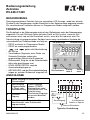
Operating Instructions
Timers
E5-248-C1420
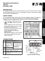
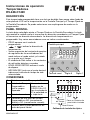
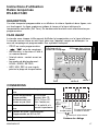
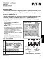
FRONT PANEL
The key below each digit sets the Set Time on the Subsidiary Display. The red reset
key resets the unit to zero when timing up or to the Set Time when timing down.
Direction of timing is programmable. There are several annunciators as follows:
• PROG appears in programming mode
• and indicate direction of
timing
• Various segments of the suite of mode
annunciators indicate the current mode
and status at a point in time
• Relay Symbol. Indicates whether relay
contacts are open or closed
• LEVEL EDGE RETRIG indicates
triggering mode.
• HRS MIN SEC together with the decimal
point position indicates which timing
range is selected.
1234567
DESCRIPTION
This programmable timer has a two line black on silver LCD readout with the timing on
the Main Display and the Set Time on the Subsidiary Display. A wide range of modes
can be selected in programming.
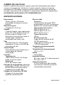
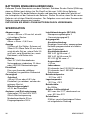
CONNECTIONS
Typical Installation Wiring
Neutral
Relay
Short to inhibit
keyboard
Live
Timer Input
External Reset
Main Display
Reset
Digit 5
Digit 1
Subsidiary Display
S
1 Common for terminals 2 + 3
2 Timing input.
Programmable
to level or edge
triggered
These inputs can
be 12-240V AC or
DC. For DC input
the polarity is
unimported
3 Reset input
4/5 Voltage free relay contacts.
Programmable to NO or NC
6/7 Connect together to disable front
panel keys

2 MN05405001E
BATTERY REPLACEMENT
Slide the cover backwards off the top of the timer to gain access to the two ½AA
lithium cells. Lift out each cell and observe the polarity sign on the PCB beneath it.
Ensure that the replacement batteries are inserted the correct way. You will need to
re-program the timer after replacing the batteries.
DO NOT THROW LITHIUM BATTERIES IN THE FIRE.
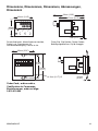
Dimensions
48 mm x 48 mm x 93 mm
(1.89" x 1.89" x 3.66")
depth including rear connector
Panel Cut-out
Square 45 +0.6 -0 mm (1.77" +0.2" -0")
Display
2 rows of 5 digits, black on silver LCD.
Upper row 6.5 mm (0.25") high
indicates Time, Lower row 3.5 mm
(0.14") high indicates Set Time.
Also mode and relay
Batteries
Two 3V ½AA Lithium batteries. 10 year
or >500,000 relay operations expected
life
Set Time
Single user selectable value within the
selected range
Accuracy
Timing
+50ms -20ms or ± 0.5% of Set Time
whichever is greater
Repeat
±0.3% of Set Time
Timing and Reset Inputs
Opto-isolated 12-240V ±10% AC or DC.
Minimum pulse width 20ms. Input
impedance 180k
Installation Category (IEC 664)
Overvoltage category II
(Pollution degree 2)
SPECIFICATIONS
Output Relay
Contacts
SPST voltage free contacts
programmable as NO or NC.
Contact Rating
8A 250V AC cosø =1
5A 250V AC cosø =0.4
8A 30V DC cosø =1
Reaction time
<20ms.
Expected life
Electrical 8A resistive load 100,000
operations
Electrical 2A resistive load 1,000,000
operations
Operating temperature
-10 to +60°C (14 to 140°F)
Storage temperature
-20 to +70°C (-4 to 158°F)
Altitude
Up to 2000m
Relative Humidity
80% max up to 31°C (88°F),
decreasing to 50% max at 40°C
(104°F)
Environmental protection
IP65 when properly installed using the
sealing gasket supplied

MN05405001E 3
english
• 1 to 99999 seconds (C3)
• 0.2 to 9999.9 seconds (B3)
• 0.20 to 999.99 seconds (A3)
• 1 to 99999 minutes (E4)
• 0.1 to 9999.9 minutes (E3)
• 0.01 to 999.99 minutes (D3)
• 1 to 99999 hours (B4)
• 0.1 to 9999.9 hours (C4)
• 0.01 to 999.99 hours (D4)
These can be displayed as elapsed time
(time up) or time remaining (time down).
Elapsed time is annunciated with
and reset is to zero.
Time remaining is annunciated with
and reset is to Preset (t, t+ or t=).
TIMING RANGE AND DISPLAY
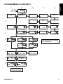
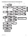
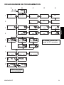
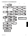
There are nine timing ranges and against each is given (in brackets) the flowchart
display which selects it.
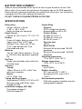
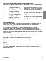
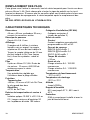
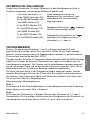
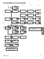
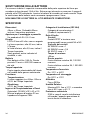
PROGRAMMING
To enter programming mode press and hold the Digit 1 and Digit 2 keys together for
3 seconds until the word PROG is annunciated.
The PROG annunciator appears on the display all the time in programing but has been
omitted from the flowchart for the sake of clarity. On the flowchart the annunciators are
very much bigger in proportion to the numeric digits than the real display. This is to aid
legibility.
Whenever you enter programming mode the options and values displayed are the
ones in current use. Go through all the stages in the flowchart using S to step
backwards and forwards though the options at each stage and Reset (R) to move on
to the next stage.
Line 1
Select one of 8 timing modes which, on the flowchart (only) overflows on to line 2.
Line 3
Select one of 9 timing ranges, hours, minutes or seconds and resolution. The selection
you make here determines the range in which the Time is displayed. This stage
overflows (on the flowchart only) on to line 4.

4 MN05405001E
Line 5
Here the programming sequence automatically takes one of three branches. The route
it takes depends on the timing mode selected above.
For modes ON DLY, OFF DLY, SS, RC= and RC= DLY, the sequence goes to column A
on the flowchart with the appropriate annunciator showing. For these modes you need
only one Set Time. The next press of Reset goes to line 7.
Modes RC DLY and RC require 2 Set Times. Enter t+ at B5, press Reset and enter t-
at B6.
For mode OS only you enter t, press Reset and then enter a Pulse Width. Pulse Width
(C6) is always in seconds to 2 places of decimals.
Line 7
Use the S key to step though LEVEL TRIGgered, EDGE TRIGgered and EDGE
RETRIGgerable and Reset to move on.
Line 8
Select increment time (up) in which reset is to zero or decrement (down) in which reset
is to Preset (Set Time).
Line 9
Select normally open (NO) or normally closed (NC) for the relay contacts.
At the end of the sequence, accept the settings by going through all the stages again
without making any changes.
NOTE:
You can also set any of the Set Times (t, t+, t- or t=) “on the fly” during normal
operation. To do this you use the digit keys and the Set Time appears on the
subsidiary display. If the timer is running in a cyclical mode, the Set Time which
changes when you press the keys is the one being annunciated at that instant.

MN05405001E 5
english
2
1
+
(3...2...1...)
LEVEL EDGE EDGE
HRS
HRS
HRS HRS
HRS HRS
HRS
MIN
MIN
MIN
MIN
MIN MIN
MIN
SEC
SEC SEC SEC
SEC
SEC SEC
SEC
R
R
R
R
RR
R
=
RE
TRIG TRIGTRIG
ABCDE
1
2
3
4
5
6
7
8
9
OFF DLY
RC
RC
RC
RC
RC
RC
+
-
=
=
OS
SS
DLY
DLY
ON DLY
REPEAT WITH
NO CHANGES
The minimum time setting
is 0.2 seconds.
PROGRAMMING FLOWCHART

6 MN05405001E
t
t
tt
tt t
t
t
pw
pw pw
t
tt
t
tt
t
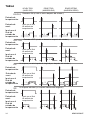
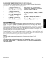
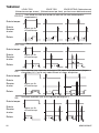
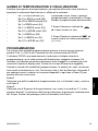
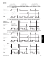
ON DLY
OFF DLY
OS
SS
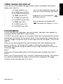
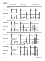
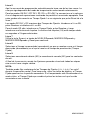
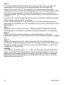
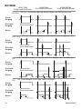
TIMING
(On Delay - relay turns on after delay t)
(Off Delay - relay turns off after delay t)
(One Shot - a single pulse of length pw, after delay t)
(Single Shot - a single pulse of length t)
LEVEL TRIG
Timing Input
Reset Input
Same as end of
timing input
Relay
Timing Input
Reset Input
Same as end of
timing input
Relay
Timing Input
Reset Input
Same as end of
timing input
Relay
Timing Input
Reset Input
Same as end of
timing input
Relay
EDGE TRIG EDGE RETRIG

MN05405001E 7
english
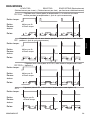
13
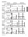
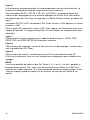
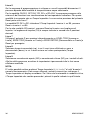
RC DLY
RC
RC DLY=
RC=
t+
t+ t+ t+ t+
t+
t+
t+
t+ t+
t-
t- t- t-
t- t-
=t
=t
=t
=t
=t =t =t
=t
=t
=t
=t
=t
=t
=t
=t
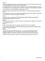
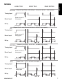
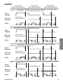
MODES
(Repeat Cycle Delay - after delay t+, relay turns on for t- ; then repeats)
(Repeat Cycle - relay turns on for time t+, off for t-; then repeats)
(Repeat Cycle Delay - as RC DLY , but both times equal; t)
(Repeat Cycle - as RC, but both times equal; t)
Timing Input
Reset Input
Same as end of
timing input
Relay
Timing Input
Reset Input
Same as end of
timing input
Relay
Timing Input
Reset Input
Same as end of
timing input
Relay
Timing Input
Reset Input
Same as end of
timing input
Relay
LEVEL TRIG
EDGE TRIG EDGE RETRIG

8 MN05405001E
WARNING
Installation and maintenance must be carried out by suitably qualified
personnel only. Hazardous voltages may be present on the connection
terminals.
Installation
This product is intended to be installed in accordance with the operating and
installation requirements of Overvoltage Category II and Pollution Degree 2 (as defined
by IEC 664).
It must be fitted in a suitable enclosure which is accessible to qualified personnel only.
The relay output circuits must be fitted with fuses suitable for the voltage and current
being switched.
Maximum fuse ratings:
250V AC @ 8A cosØ= 1 fuse rating 8A
250V AC @ 5A cosØ= 0.4 fuse rating 5A
30V DC @ 8A cosØ= 1 fuse rating 8A
All conductors carrying hazardous voltage should have external switching or
disconnect mechanisms fitted which provide at least 3 mm of contact separation in all
poles.
Failure to install or operate the unit in accordance with the above requirements
may result in the electrical safety of the unit being impaired.
Maintenance
Ensure that all power sources to the unit are isolated prior to maintenance,
inspection or cleaning.
There are no user serviceable parts inside this unit. Under no circumstances should
the case be opened.
All external wiring connections should be inspected at regular intervals. Any damaged
wiring should be replaced and any loose connections should be retightened.
Cleaning should be carried out using a dry cloth to wipe the casing of the unit.
WARNING
THIS UNIT CONTAINS A LITHIUM BATTERY AND MUST NOT BE DISPOSED
OF IN A FIRE OR EXPOSED TO TEMPERATURES BELOW -20 C OR
ABOVE +70 C.

MN05405001E 9
español
Instrucciones de operación
Temporizadores
E5-248-C1420
PANEL FRONTAL
La tecla bajo cada dígito ajusta el Tiempo Fijado en la Pantalla Secundaria. La tecla
roja resetea la unidad a cero al sincronizar en dirección ascendente o al Tiempo Fijado
al sincronizar en dirección descendente. La dirección de temporización es
programable. Hay varios anunciadores como se indica a continuación:
• PROG aparece en el modo de
programación
• y indican la dirección de
temporización
• Varios segmentos del conjunto de paneles
de regulación de los anunciadores del
modo indican el modo actual y el estado
en un punto en el tiempo.
• El símbolo de Relé indica si los contactos
de relé están abiertos o cerrados
• LEVEL EDGE RETRIG indican el modo
de disparo.
• HRS MIN SEC junto con el punto decimal
indican qué intervalo de tiempo ha sido
seleccionado.
1234567
DESCRIPCIÓN
Este temporizador programable tiene una lectura de doble línea negra sobre fondo de
color plata de LCD con la temporización en la Pantalla Principal y el Tiempo Fijado en
la Pantalla Secundaria. Se puede seleccionar una amplia gama de modos en la
programación.
CONEXIONES
Cableado de instalación típica
Neutro
Relé
Poner en Cortocircuito
para inhibir el teclado
Tensión
Entrada
de Tiempo
Reset Externo
Pantalla principal
Tecla de reset
Dígito 5
Dígito 1
Pantalla
secundaria
S
1 Entrada común de Tiempo y de Reset.
2 Entrada de Tiempo.
Programable a
nivel o margen
disparado.
Estas entradas
pueden ser de
12-240V CA o CC
Para la entrada de
CC la polaridad no
es importante.
3 Entrada de reset.
4/5 Contactos de relé libres de tensión.
Programables a NO (normalmente
abierto) o NC (normalmente cerrado).
6/7 Conectar entre sí para desactivar las
teclas del panel frontal.

10 MN05405001E
CAMBIO DE LAS PILAS
Deslice la cubierta hacia atrás en la parte superior del temporizador para obtener
acceso a las dos pilas de ½AA de litio. Levante cada pila y observe el signo de
polaridad en el PCB debajo. Asegúrese de que inserta correctamente las pilas de
recambio. Necesitará volver a programar el temporizador después de reemplazarlas.
NO DESECHE LAS PILAS DE LITIO INCINERÁNDOLAS.
Dimensiones
48 mm x 48 mm y 93 mm de
profundidad incluyendo el conector
posterior
Recorte del panel
Cuadrado 45 +0,6-0 mm
Pantalla
2 filas de 5 dígitos, negro sobre fondo
plata LCD. La fila superior de 6,5 mm
de altura indica el Tiempo, la fila
inferior de 3,5 mm de altura indica el
Tiempo Fijado. También los
anunciadores del modo y relé.
Pilas
Dos pilas de litio 3V ½AA. Duración
esperada de 10 años o >500,000 de
operaciones de relé.
Tiempo Fijado
Punto individual seleccionable por el
usuario dentro de la gama
seleccionada
Precisión
Temporización
+50ms -20ms ó ±0,5% del Tiempo
Fijado, el que sea mayor
Repetición
±0,3% del Tiempo Fijado
Entradas de temporización y de reset
Optoaisladas 12-240v ±10% CA o CC.
Mínima anchura de impulso 20ms.
Impedancia de entrada 180k
Categoría de Instalación (IEC 664)
Categoría II de sobrevoltaje
(grado de contaminación 2)
Relé de salida
Contactos
Contactos libres de tensión SPST
programables como NO (normalmente
abierto) o NC (normalmente cerrado).
Valor nominal del contacto
250VCA @ 8A cos ø= 1
250VCA @ 5A cos ø= 0,4
30VCC @ 8A cos ø= 1
Tiempo de reacción
<20ms
Duración esperada
Carga eléctrica resistiva de 8A -
100.000 operaciones
Carga eléctrica resistiva de 2A -
1.000.000 operaciones
Temperatura de funcionamiento
-10°C a +60°C
Temperatura de almacenamiento
-20°C a +70°C
Altitud
Hasta 2000m
Humedad Relativa
80% máx. hasta 31°C, disminuyendo al
50% máx. a 40 °C
Grado de protección
A IP65 cuando haya sido instalado
correctamente utilizando la junta de
estanqueidad suministrada
ESPECIFICACIONES

MN05405001E 11
español
• 1 a 99999 segundos (C3)
• 0,2 a 9999,9 segundos (B3)
• 0,20 a 999,99 segundos (A3)
• 1 a 99999 minutos (E4)
• 0,1 a 9999,9 minutos (E3)
• 0,01 a 999,99 minutos (D3)
• 1 a 99999 horas (B4)
• 0,1 a 9999,9 horas (C4)
• 0,01 a 999,99 horas (D4)
Estos pueden ser mostrados en pantalla
como Tiempo Transcurrido (ascendente)
o Tiempo Transcurrido (descendente).
El tiempo transcurrido es anunciado con
y el reset es a cero.
El Tiempo a Transcurrir está anunciado
con y el reset es a Tiempo
Predeterminado (t, t+ or t=).
INTERVALO DE TEMPORIZACIÓN Y PANTALLA
Hay nueve intervalos de temporización y al lado de cada uno se da (entre paréntesis)
la indicación del diagrama de operaciones que lo selecciona
PROGRAMACIÓN
Para introducir el modo de programación pulse y mantenga pulsadas las teclas del
Dígito 1 y del Dígito 2 a la vez durante 3 segundos hasta que se muestre en la
pantalla la palabra PROG.
El anunciador PROG aparece en la pantalla todo el tiempo que se esté en
programación pero ha sido omitido en el diagrama de operaciones para mayor
claridad. En el diagrama de operaciones los anunciadores son mucho mayores en
proporción a los dígitos numéricos que en la pantalla actual. Hemos hecho esto para
facilitar su lectura.
Siempre que introduzca el modo de programación, las opciones y los valores
mostrados son los utilizados actualmente. Vaya a través de todos los pasos en la
gráfica utilizando S para ir hacia atrás o hacia delante a través de las opciones en
cada etapa y R por Resetear para mover a la etapa siguiente.
Línea 1
Seleccione uno de los 8 modos de temporización, en el diagrama de operaciones
(sólo) se sobrepasa a la línea 2.
Línea 3
Seleccione uno de los nueve intervalos de temporización, horas, minutos o segundos
a 0, 1 o 2 lugares decimales. La selección que haga aquí determinará el intervalo que
se muestre en pantalla del Tiempo Fijado. En esta etapa se sobrepasa (sólo en el
diagrama) a la línea 4.

12 MN05405001E
Línea 5
Aquí la secuencia de programación automáticamente toma una de las tres ramas. La
ruta que siga dependerá del modo de temporización seleccionado anteriormente.
Para los modos ON DLY, OFF DLY, SS, RC= y RC=DLY, la secuencia va a la columna
A en el diagrama de operaciones mostrando en pantalla el anunciador apropiado. Para
estos modos sólo necesita un Tiempo Fijado. La vez siguiente que pulse Reset irá a la
línea 7.
Los modos RC DLY y RC requieren dos Tiempos de Fijación. Introduzca el t+ en B5,
pulse Resetear e introduzca el t- en B6.
Para el modo OS sólo, introduzca un Tiempo Fijado, pulse Resetear y luego
introduzca una Anchura de Impulso. La Anchura de Impulso (C6) está siempre dada
en segundos a 2 lugares decimales.
Línea 7
Utilice la tecla S para ir a través de NIVEL DISparado, MARGEN DISparado y
MARGEN REDISparado y Reset para continuar.
Línea 8
Seleccione el tiempo incrementado (ascendente) en que se resetea a cero o el tiempo
disminuido (descendente) en el que el reset es el tiempo de preselección (Tiempo
Fijado).
Línea 9
Seleccione normalmente abierto (NO) o normalmente cerrado (NC) para los contactos
de relé.
Al final de la secuencia, acepte las fijaciones pasando a través de todas las etapas
otra vez sin hacer ningún cambio.
NOTA:
También puede fijar cualquiera de los Tiempos de Fijación (t, t+, t- ó t=) “en vuelo”
durante la operación normal. Para hacer esto, utilice las teclas de dígitos y el Tiempo
Fijado aparecerá en la pantalla secundaria. Si el temporizador está funcionando en un
modo cíclico, el Tiempo Fijado que cambia al pulsar las teclas es el que ha sido
anunciado en ese instante.

MN05405001E 13
español
2
1
+
(3...2...1...)
LEVEL EDGE EDGE
HRS
HRS
HRS HRS
HRS HRS
HRS
MIN
MIN
MIN
MIN
MIN MIN
MIN
SEC
SEC SEC SEC
SEC
SEC SEC
SEC
R
R
R
R
RR
R
=
RE
TRIG TRIGTRIG
ABCDE
1
2
3
4
5
6
7
8
9
OFF DLY
RC
RC
RC
RC
RC
RC
+
-
=
=
OS
SS
DLY
DLY
ON DLY
REPETIR SIN
CAMBIOS
El tiempo mínimo de fijación
es de 0,2 segundos
DIAGRAMA DE OPERACIONES DE PROGRAMACIÓN

14 MN05405001E
t
t
tt
tt t
t
t
pw
pw pw
t
tt
t
tt
t
ON DLY
OFF DLY
OS
SS
TABLA
Retardo a ON (el relé se activa después del retardo t)
Retardo a OFF (el relé se desactiva después del retardo t)
Un disparo (un solo impulso de longitud pw, después del retardo t)
Un disparo individual (un impulso individual de longitud t)
LEVEL TRIG
(NIVEL DIS)
Igual que al final
de entrada de
temporización
Igual que al final
de entrada de
temporización
Igual que al final
de entrada de
temporización
Igual que al final
de entrada de
temporización
EDGE TRIG
(MARGEN DIS)
EDGE RETRIG
(MARGEN REDIS)
Entrada de
temporización:
Entrada de
reset:
Igual que al
final de
entrada de
temporización
Entrada de
temporización:
Entrada de
reset:
Igual que al
final de
entrada de
temporización
Entrada de
temporización:
Entrada de
reset:
Igual que al
final de
entrada de
temporización
Entrada de
temporización:
Entrada de
reset:
Igual que al
final de
entrada de
temporización

MN05405001E 15
español
13
RC DLY
RC
RC DLY=
RC=
t+
t+ t+ t+ t+
t+
t+
t+
t+ t+
t-
t- t- t-
t- t-
=t
=t
=t
=t
=t =t =t
=t
=t
=t
=t
=t
=t
=t
=t
DE MODOS
Repetición de ciclo con retardo (después del retardo t+, el relé se activa durante
un tiempo t-; luego se repite el ciclo)
Repetición de ciclo (el relé se activa durante un tiempo t+, se desactiva durante t-;
luego repite el ciclo)
Repetición de ciclo con retardo (como RC DLY, pero ambos tiempos son iguales; t)
Repetición de ciclo (como RC, pero ambos tiempos son iguales; t)
LEVEL TRIG
(NIVEL DIS)
EDGE TRIG
(MARGEN DIS)
EDGE RETRIG
(MARGEN REDIS)
Entrada de
temporización:
Entrada de
reset:
Igual que al final
de entrada de
temporización
Igual que al
final de
entrada de
temporización
Entrada de
temporización:
Entrada de
reset:
Igual que al final
de entrada de
temporización
Igual que al
final de
entrada de
temporización
Entrada de
temporización:
Entrada de
reset:
Igual que al final
de entrada de
temporización
Igual que al
final de
entrada de
temporización
Entrada de
temporización:
Entrada de
reset:
Igual que al final
de entrada de
temporización
Igual que al
final de
entrada de
temporización

16 MN05405001E
ATENCIÓN
LA INSTALACION Y EL MANTENIMIENTO DEBE SER EFECTUADO
CONVENIENTEMENTE POR PERSONAL CAPACITADO. SOBRE LOS
TERMINALES DE CONEXION PUEDEN ESTAR PRESENTES VOLTAJES
PELIGROSOS.
Instalación
Este producto está destinado para ser instalado de acuerdo con los requerimientos de
operación e instalación de la Categoría II de Sobrevoltaje y Grado 2 de Contaminación
(como está definido por IEC 664). Debe ser colocado en un apropiado contenedor que
sea accesible sólo al personal calificado.
Los circuitos de salida del relé deben estar instalados con fusibles apropiados de
acuerdo a los valores máximos de voltaje y corriente que se conmutan.
Máximos valores de los fusibles:
250VCA @ 8A cosØ= 1 valor del fusible 8A
250VCA @ 5A cosØ= 0.4 valor del fusible 5A
30VCC @ 8A cosØ= 1 valor del fusible 8A
Todos los conductores que lleven voltajes peligrosos deben tener instalados
mecanismos externos de interrupción o desconexión que provea una separación entre
los contactos de por lo menos 3 mm en todos los polos.
Podría afectarse la seguridad eléctrica de la unidad si ésta no se instala o se
opera de acuerdo a los requerimientos anteriormente mencionados.
Mantenimiento
Asegúrese que todas las fuentes de energía de la unidad estén aisladas con
anterioridad al mantenimiento, inspección o limpieza.
No hay ningún componente dentro de esta unidad que pueda repararse por el usuario.
Bajo ninguna circunstancia la caja debe ser abierta.
Todas las conexiones del cableado externo deben inspeccionarse periodicamente.
Deben reemplazarse todos los cables dañados y debe ajustarse toda conexión floja.
La limpieza sobre la caja de la unidad debe efectuarse utilizandose un paño seco.
ATENCIÓN
ESTA UNIDAD CONTIENE UNA BATERIA DE LITIO QUE NO DEBE SER
SITUADA CERCA DEL FUEGO NI EXPUESTA A TEMPERATURAS
FUERA DEL RANGO DE –20°C A 70°C.

MN05405001E 17
français
Instructions d’utilisation
Relais temporisés
E5-248-C1420
FACE AVANT
La touche sous chaque chiffre permet d’afficher la temporisation sur la ligne inférieure.
La touche remise à zéro ou seuil haut selon que l’appareil compte ou décompte. Le
sens de comptage est programmable. Des symboles indiquent :
• PROG en mode programmation
• sens de comptage
• les fonctions, la fonction et l’état à
un moment donné
• l’état du relais : contact ouvert ou
fermé
• les modes de déclenchement :
LEVEL, EDGE, RETRIG.
• HRS, MIN, SEC et une virgule
précise la plage de temporisation.
1234567
DESCRIPTION
Ce relais temporisé programmable a un afficheur à cristaux liquides à deux lignes, noir
sur fond argent. La ligne supérieure indique le temps et la ligne inférieure la
temporisation souhaitée (Set Time). De nombreuses fonctions sont sélectionnées par
programmation.
CONNEXIONS
Schéma de câblage
Neutre
Relais
En court-circuit pour
invalider le clavier
Phase
Entrée
temporisation
Affichage de la
valeur de comptage
RAZ
chiffre 5
chiffre 1
Affichage des valeurs
de présélection
S
1 Commun des entrées tempo et remise à
zéro.
2 Entrée temporisation.
Programmable
déclenchement par
niveau ou par front.
Ces entrées
peuvent être 12-
240 V CA ou CC.
Pour l’entrée en
CC la polarité n’a
aucune importance.
3 Entrée remise à
zéro.
4/5 Contact du relais, sans potentiel.
Programmable en NO ou NF
6/7 A ponter pour inhibition de la face avant.
Remise à zéro externe

18 MN05405001E
REMPLACEMENT DES PILES
Faire glisser vers l’arrière le couvercle, haut du relais temporisé pour l’accès aux deux
piles au lithium ½ AA. Sortir chaque pile et noter le signe de polarité sur le circuit
imprimé en dessous. S’assurer que les nouvelles piles sont insérées dans le bon sens.
Il est nécessaire de reprogrammer le relais temporisé après le remplacement des
piles.
NE PAS JETER LES PILES AU LITHIUM AU FEU.
Dimensions
48 mm x 48 mm, profondeur 93 mm y
compris le connecteur arrière
Découpe du panneau
Carrée 45 +0,6 -0 mm
Affichage
2 rangées de 5 chiffres, à cristaux
liquides, noir sur argent. La rangée
supérieure 6,5 mm de haut indique le
Temps, la rangée inférieure de 3,5 mm
de haut indique le Set Time (temps
fixé). Aussi les symboles : mode et
relais.
Piles
2 piles au lithium 3V ½AA. Durée de
vie prévue : 10 ans ou >500,000 de
manoeuvres pour le relais.
Temporisation
Une présélection réglable par
l’utilisateur dans la plage affichée.
Précision
Temporisation
+50 ms, -20 ms ou ±0,5% du Set Time,
le plus grand des deux
Répétition
±0,3% du Set Time
Entrées de temporisation et remise à
zéro
Isolation optique 12-240 V ±10% CA ou
CC. Largeur minimum d’impulsion 20
ms. Impédance d’entrée 180 kohms.
Catégorie d’installation (IEC 664)
Catégorie surtension II
(niveau de pollution 2)
Relais de sortie
Contact
Contact unipolaire sans potentiel,
programmable en NO ou NF.
Pouvoir de coupure
250VCA @ 8A cosØ= 1
250VCA @ 5A cosØ= 0,4
30VCC @ 8A cosØ= 1
Temps de réaction
< 20 ms
Durée de vie
Charge résistive 8 A : 100.000
manoeuvres
Charge résistive 2 A : 1.000.000
manoeuvres
Température de fonctionnement
-10°C à +60°C
Température de stockage
-20°C à +70°C
Altitude
Jusqu’à 2000m
Rapport d’humidité
80% max jusqu’à 31°C ; 50% max à
40°C
Protection
IP65 si correctement installé et avec le
joint d’étanchéité fourni
CARACTERISTIQUES TECHNIQUES

MN05405001E 19
français
• 1 à 99999 secondes (C3)
• 0,2 à 9999,9 secondes (B3)
• 0,20 à 999,99 secondes (A3)
• 1 à 99999 minutes (E4)
• 0,1 à 9999,9 minutes (E3)
• 0,01 à 999,99 minutes (D3)
• 1 à 99999 heures (B4)
• 0,1 à 9999,9 heures (C4)
• 0,01 à 999,99 heures (D4)
Elles peuvent être affichées comme
Temps écoulé (totalisation) ou Temps à
s’écouler (compte à rebours).
Le temps écoulé est annoncé à l’aide de
et la remise est au zéro.
Le temps à s’écouler est annoncé à
l’aide de et la remise est sur
Preset (préréglage) (t, t+ or t=).
PLAGE DE TEMPORISATION ET AFFICHAGE
Il y a neuf plages de temporisation et, pour chacune d’entre elles est donné (entre
parenthèses) son affichage dans l’organigramme.
PROGRAMMATION
Pour entrer dans le mode programmation, appuyez simultanément sur les touches
Chiffre 1 et Chiffre 2 pendant 3 secondes jusqu’à ce que le mot PROG soit affiché.
PROG est affiché pendant tout le temps de la programmation, mais il a été omis dans
l’organigramme pour plus de clarté. Sur l’organigramme, les messages et symboles
sont beaucoup plus grands, en proportion, par rapport aux chiffres numériques, que
l’affichage réel. Ceci pour une meilleure lisibilité.
Chaque fois qu’on entre en mode programmation, les options et valeurs affichées sont
celles utilisées à ce moment A l’aide de la touche S faites défiler les options de chaque
séquence, la Remise à zéro (R) fait passer à l’étape suivante.
Ligne 1
Choix du mode de temporisation parmi les 8 fonctions des lignes 1 et 2.
Ligne 3
Choix d’une plage de temporisation parmi les 9 disponibles (lignes 3 et 4), heures,
minutes ou secondes avec 1, 2 décimales ou sans. Ce choix détermine la plage du
« set time » affiché.

20 MN05405001E
Ligne 5
Ici la séquence de programmation suit automatiquement une des trois branches. Le
chemin suivi dépend du mode de temporisation choisi ci-dessus.
Pour les modes ON DLY, OFF DLY, SS, RC= et RC=DLY, la séquence passe à la
colonne A de l’organigramme et le symbole approprié est affiché. Pour ces modes il
n’est besoin que d’un Set Time. En appuyant sur Reset (Remise à zéro), on passe à la
ligne 7.
Les modes RC DLY et RC nécessitent 2 Set Times. Entrer t+ à B5, appuyer sur Reset
et entrer t- à B6.
Pour le mode OS uniquement, entrer un Set Time, appuyer sur Reset puis entrer une
Largeur d’Impulsion. La Largeur d’Impulsion (C6) est toujours en secondes avec deux
décimales.
Ligne 7
Utiliser la touche S pour sélectionner le mode de déclenchement : LEVEL TRIG,
EDGE TRIG, ou EDGE RETRIG et Reset pour continuer.
Ligne 8
Choix du sens de comptage : remise à zéro vers zéro ou décomptage : remise à zéro
vers la présélection (Set Time).
Ligne 9
Choix du sens du contact : normalement ouvert NO ou normalement fermé NF.
A la fin de la séquence, faire un cycle complet sans changement pour validation des
réglages.
NOTA:
Il est aussi possible de régler un des Set Times (t, t+, t- ou t=) « au vol » pendant le
fonctionnement normal. Pour cela, vous utilisez les touches chiffres et le Set Time
s’affiche sur la ligne inférieure. Si le relais temporisé marche en mode cyclique, le Set
Time qui change, quand on appuie sur les touches, est celui qui est affiché à cet
instant.
La pagina si sta caricando...
La pagina si sta caricando...
La pagina si sta caricando...
La pagina si sta caricando...
La pagina si sta caricando...
La pagina si sta caricando...
La pagina si sta caricando...
La pagina si sta caricando...
La pagina si sta caricando...
La pagina si sta caricando...
La pagina si sta caricando...
La pagina si sta caricando...
La pagina si sta caricando...
La pagina si sta caricando...
La pagina si sta caricando...
La pagina si sta caricando...
La pagina si sta caricando...
La pagina si sta caricando...
La pagina si sta caricando...
La pagina si sta caricando...
La pagina si sta caricando...
La pagina si sta caricando...
La pagina si sta caricando...
La pagina si sta caricando...
-
 1
1
-
 2
2
-
 3
3
-
 4
4
-
 5
5
-
 6
6
-
 7
7
-
 8
8
-
 9
9
-
 10
10
-
 11
11
-
 12
12
-
 13
13
-
 14
14
-
 15
15
-
 16
16
-
 17
17
-
 18
18
-
 19
19
-
 20
20
-
 21
21
-
 22
22
-
 23
23
-
 24
24
-
 25
25
-
 26
26
-
 27
27
-
 28
28
-
 29
29
-
 30
30
-
 31
31
-
 32
32
-
 33
33
-
 34
34
-
 35
35
-
 36
36
-
 37
37
-
 38
38
-
 39
39
-
 40
40
-
 41
41
-
 42
42
-
 43
43
-
 44
44


Eaton E5-248-C1420 Istruzioni per l'uso
- Tipo
- Istruzioni per l'uso
- Questo manuale è adatto anche per
in altre lingue
- English: Eaton E5-248-C1420 Operating instructions
- français: Eaton E5-248-C1420 Mode d'emploi
- español: Eaton E5-248-C1420 Instrucciones de operación
- Deutsch: Eaton E5-248-C1420 Bedienungsanleitung
Altri documenti
-
Comelit 3328 Technical Manual
-
Schneider Electric RE17LCBM Istruzioni per l'uso
-
SICK WS/WE260, WE260, WS260 Istruzioni per l'uso
-
ABB CT-WBS Istruzioni per l'uso
-
 Allen-Bradley MINOTAUR MSR178DP Guida d'installazione
-
Eurotherm 3200 Guida utente
-
-
-
-
PRASTEL Fingerkey Manuale del proprietario
