Moog Videolarm NTK-SD-3 Installation And Operation Instructions Manual
- Categoria
- Accessori per telecamere di sicurezza
- Tipo
- Installation And Operation Instructions Manual
Questo manuale è adatto anche per

www.videolarm.com
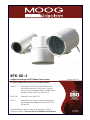
N T K - S D - 3
Intelligent Infrared Light and PTZ Outdoor Camera System
Installation and Operation Instructions for the following models:
NTK-SD-3 Analog night vision PTZ system, with IR illuminator that
automatically adjusts based on the camera’s zoom level,
dust-proof camera housing with 36x Day and Night camera,
360 degree rotation, RS422 Pelco D&P protocols
NTK-SD-3N Network (IP) version of NTK-SD-3
NT-SD-3 Analog PTZ system, dust-proof camera housing with 36x
Day and Night camera, 360 degree rotation, RS422 Pelco
D&P protocols
Before attempting to connect or operate this product, please read these
instructions completely. To be used with the 81-IN5409 Instruction Manual
CERTIFIED
81-IN5447
09-27-2010

IMPORTANT SAFEGUARDS SAFETY PRECAUTIONS
UNPACKING
SERVICE
1 Read these instructions.
2 Keep these instructions.
3 Heed all warnings
4 Follow all instructions.
5 Do not use this apparatus near water.
6 Clean only with damp cloth.
7 Do not block any of the ventilation openings. Install in accordance with the
manufacturers instructions.
8 Cable Runs- All cable runs must be within permissible distance.
9 Mounting - This unit must be properly and securely mounted to a supporting
structure capable of sustaining the weight of the unit.
Accordingly:
a. The installation should be made by a qualied installer.
b. The installation should be in compliance with local codes.
c. Care should be exercised to select suitable hardware to install the unit, taking into
account both the composition of the mounting surface and the weight of the unit.
10 Do not install near any heat sources such as radiators, heat registers, stoves, or other
apparatus ( including ampliers) that produce heat.
11 Do not defeat the safety purpose of the polarized or grounding-type plug. A
polarized plug has two blades with one wider than the other. A grounding type
plug has two blades and a third grounding prong. The wide blade or the third
prong are provided for your safety. When the provided plug does not t into your
outlet, consult an electrician for replacement of the obsolete outlet.
12 Protect the power cord from being walked on or pinched particularly at plugs,
convenience receptacles, and the point where they exit from the apparatus.
13 Only use attachment/ accessories specied by the manufacturer.
14 Use only with a cart, stand, tripod, bracket, or table specied by the manufacturer,
or sold with the apparatus. When a cart is used, use caution when moving the cart/
apparatus combination to avoid injury from tip-over.
15 Unplug this apparatus during lighting storms or when unused for long periods of time.
16 Refer all servicing to qualied service personnel. Servicing is required when the
apparatus has been damaged in any way, such as power-supply cord or plug is
damaged, liquid has been spilled of objects have fallen into the apparatus, the
apparatus has been exposed to rain or moisture, does not operate normally, or
has been dropped.
Be sure to periodically examine the unit and the supporting structure to make sure that the integrity
of the installation is intact. Failure to comply with the foregoing could result in the unit separating
from the support structure and falling, with resultant damages or injury to anyone or anything struck
by the falling unit.
Unpack carefully. Electronic components can be
damaged if improperly handled or dropped. If an item
appears to have been damaged in shipment, replace
it properly in its carton and notify the shipper.
Be sure to save:
1 The shipping carton and packaging material.
They are the safest material in which to make future
shipments of the equipment.
2 These Installation and Operating Instructions.
If technical support or service is needed, contact us at
the following number:
The lightning ash with an arrowhead symbol,
within an equilateral triangle, is intended to
alert the user to the presence of non-insulated
“dangerous voltage” within the product’s
enclosure that may be of sufcient magnitude
to constitute a risk to persons.
Este símbolo se piensa para alertar al usuario a la presencia
del “voltaje peligroso no-aisIado” dentro del recinto de los
productos que puede ser un riesgo de choque eléctrico.
Ce symbole est prévu pour alerter I’utilisateur à la presence
“de la tension dangereuse” non-isolée dans la clôture de
produits qui peut être un risque de choc électrique.
Dieses Symbol soll den Benutzer zum Vorhandensein der
nicht-lsolier “Gefährdungsspannung” innerhalb der
Produkteinschließung alarmieren die eine Gefahr des
elektrischen Schlages sein kann.
Este símbolo é pretendido alertar o usuário à presença “di
tensão perigosa non-isolada” dentro do cerco dos produtos
que pode ser um risco de choque elétrico.
Questo simbolo è inteso per avvertire I’utente alla presenza
“di tensione pericolosa” non-isolata all’interno della
recinzione dei prodotti che può essere un rischio di scossa
elettrica
.
The exclamation point within an equilateral
triangle is intended to alert the user to
presence of important operating and
maintenance (servicing) instructions in the
literature accompanying the appliance.
Este símbolo del punto del exclamation se piensa para
alertar al usuario a la presencia de instrucciones importantes
en la literatura que acompaña la aplicación.
Ce symbole de point d’exclamation est prévu pour alerter
l’utilisateur à la presence des instructions importantes dans
la littérature accompagnant l’appareil.
Dieses Ausruf Punktsymbol soll den Benutzer zum
Vorhandensein de wichtigen Anweisungen in der Literatur
alarmieren, die das Gerät begleitet.
Este símbolo do ponto do exclamation é pretendido alertar o
usuário à presença de instruções importantes na literatura
que acompanha o dispositivo.
Questo simbolo del punto del exclamaton è inteso per
avvertire l’utente alla presenza delle istruzioni importanti nella
letteratura che accompagna l'apparecchio.
TECHNICAL SUPPORT
AVAILABLE 24 HOURS
1- 800 - 554 -1124
RISK OF ELECTRIC SHOCK
DO NOT OPEN
CAUTION
CAUTION: TO REDUCE THE RISK OF
ELECTRIC SHOCK, DO NOT REMOVE
COVER ( OR BACK). NO USER- SERVICE-
ABLE PARTS INSIDE. REFER SEVICING
TO QUALIFIED SERVICE PERSONNEL.

LIMITED WARRANTY FOR VIDEOLARM INC. PRODUCTS
VIDEOLARM INC. warrants this Product to be free fromdefectsin material or workmanship,as follows:
PRODUCTCATEGORY PARTS LABOR
All Enclosuresand Electronics Five (5) Years Five (5) Years
Pan/Tilts Three (3) Years **6 months if used in autoscan Three (3) Years **6 months if usedin autoscan
Poles/PoleEvators Three (3) Years Three(3) Years
Warrior/Q-View/I.R.Illuminators Five (5) Years Five (5) Years
Controllers Five (5) Years Five (5) Years
PowerSupplies Five (5) Years Five (5) Years
AccessoryBrackets Five (5) Years Five (5) Years
During the labor warranty period, to repair the Product,Purchaserwill either return the defective product,freight prepaid,or deliver it to Videolarm Inc.
Decatur GA.The Productto be repaired is to be returned in either its original carton or a similar package
an equal degree of protection with a
RMA# (Return Materials Authorization number) displayed on the outer box or packing slip. To obtain a RMA#you must contactour TechnicalSupport
Team at 800.554.1124,extension 101.Videolarm will return the repaired Productfreight prepaid to Purchaser.Videolarm is not obligated to provide
Purchaserwith a substitute unit during the warranty period or at any time. After the applicable warranty period, Purchasermust pay all labor and/or
parts charges.
1.NOTIFICATIONOF CLAIMS: WARRANTYSERVICE:If Purchaser believes that the Product is defective in material or workmanship, then written notice
with an explanation of the claim shall be given promptly by Purchaser to Videolarm but all claims for warranty service must be made within the
warranty period. If after investigation Videolarm determines that the reported problem was not covered by the warranty, P
urchaser shall pay Videolarm
for the cost of investigating the problem at its then prevailing per incident billable rate. No repair or replacement of any Product or part thereof shall
extend the warranty period as to the entire Product. The
warranty on the repaired part only shall be in for a period of ninety (90) days
following the repair or replacement of that part or the remaining period of the Product parts warranty, whichever is greater.
2.EXCLUSIVE REMEDY: ACCEPTANCE:Purchaser’s exclusive remedy and Videolarm’s sole obligation is to supply (or pay for) all labor necessary to repair
any Product found to be defective within the warranty period and to supply, at no extra charge, new or rebuilt replacements for defective parts.
3.EXCEPTIONS TO LIMITED WARRANTY: Videolarm shall have no liability or obligation to Purchaser with respect to any Product requiring service
during the warranty period which is subjected to any of the following: abuse, improper use: negligence, accident, lightning damage or other acts
of God (i.e., hurricanes, earthquakes),
failure of the end-user to follow the directions outlined in the product instructions, failure of the
end-user to follow the maintenance procedures recommended by the International Security Industry Organization, written in product instructions,
or recommended in the service manual for the Product. Furthermore, Videolarm shall have no liability where a schedule is
for regular
replacement or maintenance or cleaning of certain parts (based on usage) and the end-user has failed to follow such schedule; attempted repair by
personnel; operation of the Product outside of the published environmental and electrical parameters, or if such Product’s original
(trademark, serial number) markings have been defaced, altered, or removed. Videolarm excludes from warranty coverage Products sold
AS IS and/or WITH ALL FAULTS and excludes used Products which have not been sold by Videolarm to the Purchaser. All software and accompanying
documentation furnished with, or as part of the Product is furnished “AS IS” (i.e., without any warranty of any kind), except where expressly provided
otherwise in any documentation or license agreement furnished with the Product.
4.PROOF OF PURCHASE: The Purchaser’s dated bill of sale must be retained as evidence of the date of purchase and to establish warranty eligibility.
DISCLAIMEROF WARRANTY
EXCEPT FOR THE FOREGOING WARRANTIES, VIDEOLARM HEREBY DISCLAIMS AND EXCLUDES ALL OTHER WARRANTIES, EXPRESS OR IMPLIED,
INCLUDING, BUT NOT LIMITED TO ANY AND/OR ALL IMPLIED WARRANTIES OF MERCHANTABILITY, FITNESS FOR A PARTICULAR PURPOSE AND/OR ANY WARRANTY WITH
REGARD TO ANY CLAIM OF INFRINGEMENT THAT MAY BE PROVIDED IN SECTION 2-312(3) OF
THE UNIFORM COMMERCIAL CODE AND/OR IN ANY OTHER COMPARABLE
STATE STATUTE. VIDEOLARM HEREBY DISCLAIMS ANY REPRESENTATIONS OR WARRANTY THAT THE PRODUCT IS COMPATIBLE WITH ANY COMBINATION OF NON-VIDEOLARM
PRODUCTS OR NON-VIDEOLARM RECOMMENDED PRODUCTS PURCHASER CHOOSES TO CONNECT TO PRODUCT.
LIMITATION OF LIABILITY
THE LIABILITY OF VIDEOLARM, IF ANY, AND PURCHASER’S SOLE AND EXCLUSIVE REMEDY FOR DAMAGES FOR ANY CLAIM OF ANY KIND
WHATSOEVER, REGARDLESS OF THE LEGAL THEORY AND WHETHER ARISING IN TORT OR CONTRACT, SHALL NOT BE GREATER THAN THE ACTUAL PURCHASE PRICE OF THE
PRODUCT WITH RESPECT TO WHICH SUCH CLAIM IS MADE. IN NO EVENT SHALL VIDEOLARM BE LIABLE TO PURCHASER FOR ANY SPECIAL, INDIRECT, INCIDENTAL, OR
CONSEQUENTIAL DAMAGES OF ANY KIND INCLUDING, BUT NOT LIMITED TO, COMPENSATION, REIMBURSEMENT OR DAMAGES ON ACCOUNT OF THE LOSS OF PRESENT
OR PROSPECTIVE PROFITS OR FOR ANY OTHER REASON WHATSOEVER.
/tour operation
/tour operation
**6 months if used in autoscan
/tour operation
**6 months if used in autoscan
/tour operation
SView Series Five (5) Years
Five (5) Years
The limited warranty stated in these product instructions is subject to all of the following terms and conditions:
TERMS AND CONDITIONS

NTK-SD-3
NTK-SD-3N
NT-SD-3
24 VAC
90 W
Tools Required: .100” Flat Head Screwdriver
Phillips Head Screwdriver
24 VAC
90 W
Requeridas: Destornillador Principal Phillips
Del Destornillador Principal
Plano Del 100"
24 VCA
90 W
Les Outils Ont exigé : Tournevis Principal Phillips De
Tournevis Principal Plat De 100".
24 VAC
90 W
Werkzeug-Erfordert: 100"Flacher
Hauptschraubenzieher-
Kreuzkopfhauptschraubenzieher
24 VAC
90 W
Requereram: Chave de fenda Principal
Phillips Da Chave de fenda
Principal Lisa Do 100"
24 VCA
90 W
Di Attrezzi Massimi
Hanno richiesto: Cacciavite Capo "phillips"
Del Cacciavite Capo Piano
Del 100"
Electrical Specifications
Power 24VAC
Class 2 Only
!!
Français
Deutsch
Italiano
Portuguese
Español
English
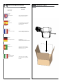
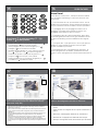
Contents of Box

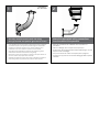
1
Securely mount bracket to wall. Pull wiring
through bracket and position grommet as shown.
• Con seguridad soporte del montaje a emparedar. Tire del cableado
a través del soporte y del ojal de la posición según lo demostrado.
• Solidement parenthèse de bâti à murer. Tirez le câblage par la
parenthèse et le canon isolant de position comme montré.
• Sicher Einfassung Haltewinkel wall. Ziehen Sie Verdrahtung durch
Haltewinkel und Position Gummimuffe, wie gezeigt.
• Firmemente suporte da montagem a wall. Puxe a fiação através do
suporte e do ilhó da posição como mostrado.
• Saldamente staffa del supporto da wall. Tiri i collegamenti tramite la
staffa ed il gommino di protezione di posizione come indicato.
FOR PENDENT/
WALL MOUNTING
6
Make the appropriate wiring connections
from the dome to the pendant.
• Hacer las conexiones de cableado de la cúpula de la
pendiente.
• Faites le câblage de la coupole de la suspension.
• Nehmen Sie die entsprechenden Kabel-Verbindungen von der
Kuppel auf den Anhänger.
• Faça as conexões de cabos da cúpula para o pingente.
• Apportare le opportune connessioni cablaggio dalla cupola a
ciondolo.
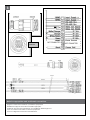
1
2

Make the appropriate male and female connections.
• Haga las conexiones masculinas y femeninas apropiadas.
• Établissez les rapports masculins et femelles appropriés.
• Stellen Sie die passenden männlichen und weiblichen Beziehungen her.
• Faça as conexões masculinas e fêmeas apropriadas.
• Faccia i collegamenti maschii e femminili adatti.
Front of
connector
NOT CONNECTED
NOT CONNECTED
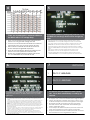
3

To set camera address (analog only) execute a “GO
TO PRESET 95” use the joy stick to move through the
menu
• Para fijar la dirección de la cámara (análogo solamente) ejecute “VAN A
PREESTABLECER” un uso 95 el palillo de alegría de moverse a través del menú
• Pour placer l'adresse d'appareil-photo (analogue seulement) exécutez « VONT
PRÉRÉGLER » une utilisation 95 le bâton de joie de se déplacer par le menu
• SUm Kameraadresse (nur Entsprechung) einzustellen führen Sie einen „GEHEN
Gebrauch 95 EINZUSTELLEN“ der Steuerknüppel sich durch das Menü zu bewegen
durch
• Para ajustar o endereço da câmera (analog somente) execute “VÃO
PRÉ-AJUSTAR” um uso 95 a vara de alegria mover-se através do menu
• Per fissare l'indirizzo della macchina fotografica (analogo soltanto) esegua
“VANNO PRESTABILIRE„ un uso 95 il bastone di gioia muoversi attraverso il menu
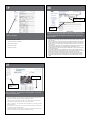
MM
2
AWG
,5 ,75 1,0 1,5 2,5 4 6
22 20 18 16 14 12 10
The beam angle may be adjusted on the
bottom of the unit.
• Éstos se recomiendan las distancias máximas para
24VAC con una gota del voltage del 10%.
• Ceux-ci sont recommandés des distances maximum
pour 24VAC avec une chute de tension de 10%.
• Diese werden maximale Abstände für 24VAC mit
einem 10% Spannungsabfall empfohlen.
• Estes são recomendados distâncias máximas para
24VAC com uma queda de tensão de 10%.
• Questi sono suggeriti distanze massime per 24VAC
con una differenza de potenziale di 10%.
12
These are recommended maximum distances
for 24VAC with a 10% voltage drop.
5
4
Once you have navigated to the “Set site address” menu, use the joystick
to scroll down to the “new address” line. Move the joystick to the right to
change the camera address. The address will be set once you exit the
camera menu.
• Una vez que usted ha navegado “fijó al menú de la dirección del sitio”, utiliza la palanca de mando
para enrollar abajo a la línea de la “nueva dirección”. Mueva la palanca de mando a la derecha
de cambiar la dirección de la cámara. La dirección le será fijado una vez salida el menú de la
cámara.
• Une fois que vous avez dirigé au menu « placiez d'emplacement adresse », utilisez le manche pour
faire descendre l'écran à la ligne de « nouvelle adresse ». Déplacez le manche vers la droite de
changer l'adresse d'appareil-photo. L'adresse vous sera placé une fois sortie le menu d'appareil-
photo.
• Sobald Sie zum „einstellten Aufstellungsortadressen“ Menü, benutzen den Steuerknüppel, um zur
Linie „der neuen Adresse“ unten in einer Liste zu verzeichnen gesteuert haben. Verschieben Sie den
Steuerknüppel rechts, die Kameraadresse zu ändern. Die Adresse wird einmal Sie Ausgang das
Kameramenü eingestellt.
• Uma vez que você navegou “ajustou ao menu do endereço do local”, usa o manche para enrolar
para baixo “a linha do endereço novo”. Mova o manche para a direita mudar o endereço da
câmera. O endereço sê-lo-á ajustado uma vez saída o menu da câmera.
• Una volta che avete traversato “fissaste al menu di indirizzo del luogo„, utilizzate la barra di
comando per arrotolare giù “alla linea di nuovo indirizzo„. Sposti la barra di comando verso la
destra cambiare l'indirizzo della macchina fotografica. L'indirizzo lo sarà regolato una volta uscita il
menu della macchina fotografica.
6
PROTOCOLS
The NiteTrac Pan/Tilt support the above proto-
cols. This is done automatically no settings are
required.
• La ayuda de la NiteTrac Pan/Tilt los protocolos antedichos.
Se requiere esto se hace automáticamente ningunos ajustes.
• L'appui de la NiteTrac Pan/Tilt les protocoles ci-dessus. Ceci
est fait automatiquement aucuns arrangements sont exigés.
• Die NiteTrac Pan/Tilt Unterstützung die oben genannten
Protokolle. Diesem wird automatisch keine Einstellungen
werden angefordert getan.
• A sustentação da NiteTrac Pan/Tilt os protocolos acima. Isto
é feito automaticamente nenhuns ajustes é requerido.
• Il supporto di NiteTrac Pan/Tilt i suddetti protocolli. Ciò è fatta
automaticamente nessun regolazioni è richiesta.
1 PELCO P 4800/9600
2 PELCO D 4800/9600
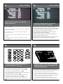
7

When using Videolarm controller; to enter the
menu; select the camera you wish to control.
• Al usar el regulador de Videolarm; para incorporar el menú;
seleccione la cámara fotográfica que usted desea contro-
lar.
• En utilisant le contrôleur de Videolarm ; pour écrire le menu ;
choisissez l'appareil-photo que vous souhaitez commander.
• Wenn Videolarm Steuerpult verwendet wird; das Menü
eintragen; wählen Sie die Kamera vor, die Sie steuern
möchten.
• Ao usar o controlador de Videolarm; para incorporar o
menu; selecione a câmera que você deseja controlar.
• Nel usando il regolatore di Videolarm; per entrare nel menu;
selezioni la macchina fotografica che desiderate controllare.
1
2
3
4
5
6
7 8
9
0
*
#
1, 2, 3...
F
Camera
MENU DRIVEN SETTINGS (Analog)
Then press 95 followed by the Preset
button ( ).
• Entonces la prensa 95 siguió por preestableció el
botón ( ).
• Alors la pression 95 a suivi de a préréglé le bouton
( ).
• Dann folgte Presse 95 von einstellte Taste ( ).
• Então a imprensa 95 seguiu pelo pré-ajustou a
tecla ( ).
• Allora la pressa 95 è seguito dal ha prestabilito il
tasto ( ).
1
2
3
4
5
6
7 8
9
0
*
#
1, 2, 3...
F
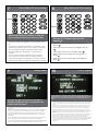
MENU DRIVEN SETTINGS (Analog)
Presets
DISPLAY / MENU
Use pan left/right control on the controller to
navigate through the menu. Pan up/down are
used to enter sub menus.
• Utilice el control dejado/correcto de la cacerola en el regulador para navegar a
través del menú. La cacerola up/down se utiliza para incorporar menús
secundarios.
• Employez commande laissée/bonne de casserole sur le contrôleur pour diriger par
le menu. La casserole haut/bas sont utilisées pour écrire les menus secondaires.
• Verwenden Sie gelassene/rechte Steuerung der Wanne auf dem Steuerpult, um
durch das Menü zu steuern. Die Auf-/Ab Wanne werden benutzt, um Vormenüs
einzutragen.
• Use controle deixado/direito da bandeja no controlador para navegar através do
menu. A bandeja up/down é usada para incorporar menus secundários.
• Usi controllo lasciato/giusto della vaschetta sul regolatore per traversare attraverso
il menu. La vaschetta up/down è utilizzata per entrare nei menu secondari.
utilizzata per entrare nei
DISPLAY / COMPASS
Use this submenu to activate compass heading. Pan up and down to
highlight selection. Pan right to execute the command. NOTE when setting
North, make sure camera is facing North before entering the camera
menu.
• Utilice este menú secundario para activar el título de compás. Cacerola hacia arriba y hacia abajo
para destacar la selección. La derecha de la cacerola de ejecutar el comando. La NOTA al fijar el
norte, se cerciora de que la cámara sea revestimiento del norte antes de incorporar el menú de la
cámara.
• Employez ce menu secondaire pour activer le titre de boussole. Casserole en haut et en bas pour
accentuer le choix. Droite de casserole d'exécuter la commande. La NOTE en plaçant le nord,
s'assurent que l'appareil-photo est nord de revêtement avant d'écrire le menu d'appareil-photo.
• Benutzen Sie dieses Vormenü, um Kompass-Steuerkurs zu aktivieren. Wanne auf und ab, zum von
Vorwähler hervorzuheben. Wannenrecht, den Befehl durchzuführen. ANMERKUNG, wenn sie Norden
einstellt, stellen sicher, dass Kamera die Einfassung ist, die bevor sie das Kameramenü Nord ist,
einträgt.
• Use este menu secundário para ativar o título de compasso. Garimpe acima e para destacar para
baixo a seleção. Garimpe para a direita para executar o comando. ANOTE ao ajustar o norte,
certifique-se que a câmera é revestimento norte antes de incorporar o menu da câmera.
• Usi questo menu secondario per attivare l'intestazione di bussola. Vaschetta su e giù per evidenziare
selezione. Destra della vaschetta eseguire l'ordine. La NOTA quando fissa il Nord, si assicura che la
macchina fotografica sia rivestimento del nord prima di entrare nel menu della macchina
fotografica.
8
7
9 10

DISPLAY / SET NORTH
Use the “Zoom In” botton to set calibration.
Display will show OK.
• Utilice el "zumbido en" botton para fijar la calibración. La exhibición
demostrará MUY BIEN.
• Employez l'"bourdonnement dans" le botton pour placer le calibrage.
L'affichage montrera BIEN.
• Benutzen Sie den "Zoom" im botton, um Kalibrierung einzustellen.
Anzeige stellt O.K. dar.
• Use o "zumbido" no botton ajustar a calibração. A exposição mostrará
ESTÁ BEM.
• Usi "lo zoom" nel botton per regolare la calibratura. L'esposizione
mostrerà BENE.
DISPLAY / POSITION
A numeric camera position is shown on
monitor. With “Position” activated.
• Una posición numérica de la cámara fotográfica se
demuestra respecto a monitor. Con la "Posición" activó.
• Une position numérique d'appareil-photo est montrée
sur le moniteur. Avec l'"Position" a activé.
• Eine numerische Kameraposition wird auf Monitor
gezeigt. Wenn "Position" aktiviert ist.
• Uma posição numérica da câmera é mostrada no
monitor. Com "Posição" ativou.
• Una posizione numerica della macchina fotografica è
indicata sul video. Con "Posizione" ha attivato.
To set a manually controlled pattern by
joystick set Preset 71 (71,#, ).
• Para fijar un patrón manualmente controlado por el sistema
de la palanca de mando preestablezca 71(71, #, ).
• Pour placer un modèle manuellement commandé par
l'ensemble de manche préréglez 71 (71, #, ).
• Um ein manuell gesteuertes Muster durch Steuerknüppelsatz
einzustellen stellen Sie 71 ein (71, #, ).
• Para ajustar um teste padrão manualmente controlado
pelo jogo do manche pré-ajuste 71 (71, #, ).
• Per determinare un modello manualmente controllato
dall'insieme della barra di comando prestabilisca 71 (71, #,
).
1
2
3
4
5
6
7 8
9
0
*
#
1, 2, 3...
F
Using the joystick move Pan/Tilt to desired
positions where you can record up to 128
seconds of movement.
• Con la palanca de mando mueva Pan/Tilt a las posiciones deseadas
donde usted puede registrar hasta 128 segundos de movimiento.
• En utilisant le manche déplacez Pan/Tilt aux positions désirées où vous
pouvez enregistrer jusqu'à 128 secondes de mouvement.
• Mit dem Steuerknüppel verschieben Sie Pan/Tilt auf gewünschte
Positionen, in denen Sie bis 128 Sekunden Bewegung notieren können.
• Usando o manche mova Pan/Tilt para as posições desejadas onde
você pode gravar até 128 segundos do movimento.
• Per mezzo della barra di comando sposti Pan/Tilt verso le posizioni
volute dove potete registrare fino a 128 secondi di movimento.
12
11
13 14

Setup
In order for the to access special functions of the IR and camera
menus commend strings need to be added to the web page.
(Click on the “setup” tab).
• Para que tenga acceso a las funciones especiales de los menús del IR y de la cámara
elogie las secuencias necesitan ser agregados al Web page. (Chasque encendido la
lengüeta de la “disposición”).
• Pour qu'accède à des fonctions spéciales des menus d'IR et d'appareil-photo recomman
dez les cordes doivent être ajoutés à la page Web. (Cliquez sur dessus l'étiquette de «
installation »).
• Damit auf spezielle Funktionen der IR-und Kameramenüs empfehlen Sie Schnüre muss
der Webseite hinzugefügt werden zurückgreift. (Klicken Sie an den „Einstellungs“
Vorsprung).
• Para que alcance funções especiais dos menus do IR e da câmera recomende cordas
precisam de ser adicionados ao Web page. (Estale sobre a aba da “instalação”).
• In modo che per accedere alle funzioni speciali dei menu della macchina fotografica e di
IR lodi le stringhe devono aggiungersi al Web page. (Scatti sopra la linguetta “di messa a
punto„).
Click on “PTZ Configuration” then click on “Advanced”
• Chasque encendido la “configuración de PTZ” entonces chascan encendido
“avanzó”
• Cliquez sur dessus la « configuration de PTZ » cliquent sur alors dessus « a
avancé »
• Klicken Sie an „PTZ Konfiguration“ klicken dann an „voranbrachte“ an
• Estale sobre de “a configuração PTZ” estalam então sobre “avançou”
• Scatti sopra “la configurazione di PTZ„ allora si scattano sopra “ha avanzato„
En “controles”. chasque encendido uno de los ajustes
mencionados del control, después la prensa
se modifica. Usted
Press Preset 71 to stop recording (71,*, ).
Preset 71, to start pattern.
• Presione preestablecen 71 para parar el registrar (71, *, ).
Preestablezca 71, para comenzar el patrón.
• Serrez prérèglent 71 pour cesser d'enregistrer (71, *, ).
Préréglez 71, pour commencer le modèle.
• Betätigen Sie sich einstellen 71, um zu notieren zu stoppen
(71, *, ). Stellen Sie 71 ein, um Muster zu beginnen.
• Pressione pré-ajustam 71 para parar de gravar (71, *, ).
Pré-ajuste 71, para começar o teste padrão.
• Premi prestabiliscono 71 per smettere di registrare (71, *, ).
Prestabilisca 71, per iniziare il modello.
1
2
3
4
5
6
7 8
9
0
*
#
1, 2, 3...
F
Presets
OTHER FEATURES:
Home Preset
Preset 34 is the “home preset”. If this preset has been defined,
then the NiteTrac will always go to this preset when the unit is
powered up.
• La precolocación 34 es la “precolocación casera”. Si se ha
definido esta precolocación, después el NiteTrac irá siempre a
esta precolocación cuando la unidad se acciona para arriba.
• Le préréglage 34 est « le préréglage à la maison ». Si ce
préréglage a été défini, alors le NiteTrac ira toujours à ce
préréglage quand l'unité est mise sous tension.
• Voreinstellung 34 ist die „Hauptvoreinstellung“. Wenn diese
Voreinstellung definiert worden, dann geht das NiteTrac immer
zu dieser Voreinstellung, wenn die Maßeinheit oben angetrie-
ben.
• O pré-ajuste 34 é “o pré-ajuste home”. Se este pré-ajuste foi
definido, a seguir o NiteTrac irá sempre a este pré-ajuste
quando a unidade é psta acima.
• Il preregolamento 34 è “il preregolamento domestico„. Se
questo preregolamento sia definito, quindi il NiteTrac andrà
sempre a questo preregolamento quando l'unità è alimentata in
su.
15
17
16
18

Click on “Controls”
• Chasque encendido los “controles”
• Cliquez sur dessus les « commandes »
• Klicken Sie an „Kontrollen“
• Estale sobre “controles”
• Scatti sopra “i comandi„
In “controls”. click on one of the listed control settings, then press modify.
You will need to change the IP address listed in the control string to match
the one you assigned to the product once done click on “save” then go
back to live view
• En “controles”. chasque encendido uno de los ajustes mencionados del control, después la prensa
se modifica. Usted necesitará cambiar el IP address enumerado en la secuencia del control para
emparejar el que usted asignó al producto hecho una vez chasca encendido “excepto” entonces
vuelve vivir visión
• Dans des « commandes ». cliquez sur dessus un des arrangements énumérés de commande, puis
la presse modifient. Vous devrez changer l'IP address énuméré dans la corde de commande pour
assortir celui que vous avez assigné au produit une fois fait cliquez sur dessus « sauf » retournez
alors pour vivre vu
• „In den Kontrollen“. klicken Sie an eine der aufgeführten Steuereinstellungen, dann ändern Presse.
Sie müssen das IP address ändern, das in der Steuerschnur verzeichnet wird, um das
zusammenzubringen, das Sie dem einmal getanen Produkt klicken an „außer“ gehen dann zurück,
zu leben Ansicht zuwiesen
• Em “controles”. estale sobre um dos ajustes listados do controle, a seguir a imprensa modifica.
Você precisará de mudar o IP address alistado na corda do controle para combinar esse que você
atribuiu ao produto feito uma vez estala sobre “excepto” vai então para trás viver vista
• “Nei comandi„. scatti sopra una delle regolazioni elencate di controllo, quindi la pressa modifica.
Dovrete cambiare il IP address elencato nella stringa di controllo per abbinare quello che avete
assegnato al prodotto fatto una volta vi scattate sopra “salvo„ allora andate indietro vivere vistae il
modello.
Modify
Control setting
Click on “Ctrl panel”. You will see the control sting button. To use them
just click on the desired one.
•
Chasque encendido el “panel del Ctrl”. Usted verá el botón de la picadura del
control. Para utilizarlos apenas chasque encendido deseado.
• Cliquez sur dessus le « panneau de CTRL ». Vous verrez le bouton de piqûre de
commande. Pour les employer cliquez sur juste dessus désiré.
• Click on “Ctrl panel”. You will see the control sting button. To use them just click
on the desired one.
• Estale sobre do “o painel CTRL”. Você verá a tecla da picada do controle. Para
usá-los apenas estale sobre desejado.
• Chasque encendido el “panel del Ctrl”. Usted verá el botón de la picadura del
control. Para utilizarlos apenas chasque encendido deseado.
Control string
buttons
CTRL panel
19
21
20

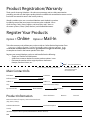
Product Registration/Warranty
Thank you for choosing Videolarm. We value your patronage and are solely committed to
providing you with only the highest quality products available with unmatched customer service
levels that are second-to-none in the security industry.
Should a problem arise, rest assure that Videolarm stands behind its products
by oering some of the most impressive warranty plans available: 3 Years
on all Housings, Poles, Power Supplies, and Accessories and 5 Years on
all camera systems (SView, QView, Warriors), and InfraRed Illuminators.
Register Your Products
Option 1: Online Option 2: Mail-In
Take a few moments and validate your purchase with our Online Product Registration Form
at
www.videolarm.com/productregistration.jsp
or complete and mail-in the bottom portion of this yer.
Register your recent Videolarm purchases and benet from the following:
• Simple and Trouble-Free RMA process
• Added into customer database to receive product updates / news
• Eliminate the need to archive original purchase documents:
Receipts, Purchase Orders, etc…
Main Contact Info
First Name: Last Name:
Professional Title: Company:
Address 1: Address 2:
City: State / Province/Country:
Zip / Postal Code: Phone Number: E-mail Address:
Product Information
Please Circle One: Business Personal
Name & Location of Company / Store where Purchased:
(City, State, Country)
Videolarm Product ID Product Description
Serial #
(Available only for Camera Systems, IR Illuminators, Wireless Devices)
PO#
Cut at the dotted Line
Place in envelope, ax stamp and mail to:
Videolarm ATTN: Warranty
2525 Park Central Ave.
Decatur, GA 30035
-
 1
1
-
 2
2
-
 3
3
-
 4
4
-
 5
5
-
 6
6
-
 7
7
-
 8
8
-
 9
9
-
 10
10
-
 11
11
-
 12
12


Moog Videolarm NTK-SD-3 Installation And Operation Instructions Manual
- Categoria
- Accessori per telecamere di sicurezza
- Tipo
- Installation And Operation Instructions Manual
- Questo manuale è adatto anche per
in altre lingue
- English: Moog Videolarm NTK-SD-3
- español: Moog Videolarm NTK-SD-3
Documenti correlati
-
Moog Videolarm S-View Pan/Tilt Series Istruzioni per l'uso
-
-
-
-
-
-
-
Moog Videolarm FDW75 Manuale utente