
Zurn Industries, LLC | Wilkins
1747 Commerce Way, Paso Robles, CA U.S.A. 93446 Ph. 855-663-9876, Fax 805-238-5766
In Canada | Zurn Industries Limited
3544 Nashua Drive, Mississauga, Ontario L4V 1L2 Ph. 905-405-8272, Fax 905-405-1292
www.zurn.com
Rev. G
Date: 1/17
Document No. BF-375
Patent No. 5, 913, 331
Product No. Model 375
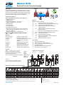
Model 375
Reduced Pressure Principle Assembly
Page 1 of 2
Options
(Suffixes can be combined)
c - with NRS shut-off valves (standard)
c FSC - with epoxy coated wye type strainer (flanged only)
c G - with grooved end NRS gate valves
c GF - with grooved inlet connection and flanged
outlet connection
c FG - with flanged inlet connection and grooved
outlet connection
c L - less shut-off valves (flanged body connections)
c MS - with Integral Relief Valve Monitor Switch
c OSY - with OS&Y gate valves
c PI - with Post Indicator gate valve
c BG - with grooved end butterfly valves with integral
supervisory switches
c –509 - with AWWA C509 gate valves
Accessories
c Repair kit (rubber only)
c Thermal expansion tank (Model XT)
c OS & Y Gate valve tamper switch (OSY-40)
c Air gap (Model AG)
c Electronic Solenoid Timer (Model EST)
c QT-SET Quick Test Fitting Set
Relief Valve discharge port:
2 1/2" - 6" - 2.75 sq. in.
8" - 10" - 3.69 sq. in.
E
F
C
D
B
E
F
G
C
D
G
A
B
H
A
MODEL 375OSYG SHOWN ABOVE
Dimensions & Weights (do not include pkg.)
NSF/ANSI 61
Application
Designed for installation on potable water lines to protect
against both backsiphonage and backpressure of contami-
nated water into the potable water supply. The Model 375
provides protection where a potential health hazard exists.
Ideal for use where lead-free* valves are required.
Standards Compliance
(Unless Otherwise Noted, Sizes 2 1/2" Thru 10")
• ASSE® Listed 1013
• IAPMO® Listed
• CSA® Certified B64.4 (2 1/2" thru 8")
• AWWA Compliant C511, and C550
• FM® Approved
• UL® Classified
• C-UL® Classified
• NYC MEA 49-01-M Vol 2
• Approved by the Foundation for Cross Connection
Control and Hydraulic Research at the University of
Southern California.
• Meets the requirements of NSF/ANSI 61*
Materials
Main valve body Ductile Iron ASTM A 536
Access covers Ductile Iron ASTM A 536
Coatings NSF Approved fusion epoxy finish
Internals Stainless steel, 300 Series
NORYL™
Fasteners Stainless Steel, 300 Series
Seal rings EPDM (FDA approved)
O-rings Buna Nitrile (FDA approved)
Springs Stainless Steel, 300 Series
Sensing line Stainless Steel, braided hose
Features
Sizes: 2 1/2", 3", 4", 6", 8", 10"
Maximum working water pressure 175 PSI
Maximum working water temperature 140°F
Hydrostatic test pressure 350 PSI
End connections (Grooved for steel pipe) AWWA C606
(Flanged) ANSI B16.1
Class 125
Attention:
Model 375 (flange body) and Model 375A
(grooved body) have different lay lengths.

ഌ
Flow Characteristics
Zurn Industries, LLC
| Wilkins
1747 Commerce Way, Paso Robles, CA U.S.A. 93446 Ph. 855-663-9876, Fax 805-238-5766
In Canada | Zurn Industries Limited
3544 Nashua Drive, Mississauga, Ontario L4V 1L2 Ph. 905-405-8272, Fax 905-405-1292
www.zurn.com
Page 2 of 2
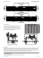
Typical Installation
Local codes shall govern installation requirements. Unless
otherwise specified, the assembly shall be mounted at a
minimum of 12" (305mm) and a maximum of 30" (762mm)
above adequate drains with sufficient side clearance for test-
ing and maintenance. The installation shall be made so that
no part of the unit can be submerged.
Speci cations
The Reduced Pressure Principle Backflow Prevention Assembly shall be certified to NSF/ANSI 61, ASSE® Listed 1013, and
supplied with full port gate valves. The main body and access cover shall be epoxy coated ductile iron (ASTM A 536), the seat
ring and check valve shall be NORYL™, the stem shall be stainless steel (ASTM A 276) and the seat disc elastomers shall be
EPDM. The checks and the relief valve shall be accessible for maintenance without removing the device from the line. The
Reduced Pressure Principle Backflow Prevention Assembly shall be a ZURN WILKINS Model 375.
OUTDOOR INSTALLATIONINDOOR INSTALLATION (375GF)
PROTECTIVE
ENCLOSURE
DIRECTION OF FLOW
12" MIN.
30" MAX.
AIR GAP
W/DRAIN
DIRECTION OF FLOW
12" MIN.
30" MAX.
-
 1
1
-
 2
2

