
CARACTERISTICAS TECNICAS
: Latón UNI en 12165:11 CW617N
: Dispositivo anti blocaje con OR en EPDM y asiento en PTFE
: Latón UNI EN 12164:11 CW614N
: 16 bar
: 5 bar
: -5 °C (con anti hielo)+100°C
: agua, agua con glicol
Cuerpo válvula esfera
Junta de retención
Eje de mando
Presión mínima de espació
Presión máxima diferencial
Temperatura uido circulante
Fluido utilizable
FAR Rubinetterie S.p.A. - www.far.eu
Hoja de instrucciones
E
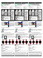
ART.307080 - 307180 - 307082 - 307182 VÀLVULA DE ZONA 3 VÍAS DESVIADORA
g.1
Rotación de 90°
g.2
Rotación de 90°
En este caso el indicador muestra que la posición de la esfera permite la entrada del uido por la vía inferior y lo desvía a la
derecha. O bien la entrada del uido puede venir de la derecha y derivarse ala vía inferior.
Antes de la instalación del servomotor controlar que el indicador de la vía de
posicionado en la dirección deseada. La válvula puede ser maniobrada mediante
el uso de un destornillador. La serigrafía situada en el eje de regulación indicada
indica la posición de la esfera
ТЕХНИЧЕСКИЕ ДАННЫЕ
Корпуси шар
Система антиблокировки
Контрольный шток
Номинальное рабочее давление
Макс.перепад давления
Температура рабочей жидкости
Рабочая жидкость
FAR Rubinetterie S.p.A. - www.far.eu
АРТ.307080 - 307180 - 307082 - 307182 3Х ХОДОВЫЕ ПЕРЕНАПРАВЛЯЮЩИЕ ЗОННЫЕ КРАНЫ
Рис.1
Поворот на 90°
Рис.2
Поворот на 90°
Такая иллюстрация показывает положение шара, когда поток входит снизу и затем перенаправляется направо. Эта же
позиция означает, что поток входит справа и затем перенаправляется вниз.
Перед установкой привода убедитесь в том, что проходное отверстие
в шаре находится в нужном положении. Кран можно отрегулировать с
помощью отвертки.. Положение шара указано трафаретом на контрольном
штоке крепления шара.
РУКОВОДСТВО ПО МОНТАЖУ
RUS
VF253 EDIZIONE N°1: 15/02/2013
: латунь CW617N
: O-ring–EPDM, посадочные кольца - PTFE
: латунь CW614N
: 16 бар
: 5 бар
: -5°С (с антифризом) +100 °С
: вода, гликолиевые смеси
АРТ.307075 - 307175 - 307077 - 307177 2-Х ХОДОВЫЕ ЗОННЫЕ КРАНЫ
Особенность зонных шаровых кранов – они имеют внутреннюю специальную систему
антиблокировки, которая предотвращает стопор шара при плохих условиях эксплуатации.
Система включает в себя два посадочных кольца из PTFE уплотненные прокладками O-ring,
которые
La válvula de zona dispone interiormente un sistema antigripaje que permite aun en las peores
condiciones de funcionamiento evitar el bloqueo de la esfera.
La válvula de tres vías con paso a L, es una válvula desviadora con entrada por vía inferior y
envío del uido termovector hacia derecha o izquierda en función de la posición del servomotor
(g.1) o viceversa de derecha ó izquierda verso la vía central (g.2). La válvula está preparada
para la conmutación de la instalación de invierno a verano y viceversa.
3-х ходовой зонный кран с Г-образным проходом направляет поток, поступающий снизу
налево или направо, в зависимости от позиции привода (рис.1); а при поступлении потока
справа или слева направляет его через центр вниз (рис.2).
Эти краны идеально подходят для коммутации систем, работающих в разные времена года.
VALVOLE DI ZONA MOTORIZZATE
CON AGGANCIO RAPIDO
CARATTERISTICHE TECNICHE
FAR Rubinetterie S.p.A. - www.far.eu
Libretto d’istruzioni
I
: Ottone UNI EN 12165:11 CW617N
: Dispositivo antibloccaggio con OR in EPDM e sedi in PTFE
: Ottone UNI EN 12164:11 CW614N
: 16 bar
: 5 bar
: -5 °C (con antigelo) +100 °C
: acqua, acqua con glicole
Corpo valvola e sfera
Guarnizione di tenuta
Asta di comando
Pressione nominale di esercizio
Pressione massima differenziale
Temperatura uido circolante
Fluidi utilizzabili
ART.307075 - 307175 - 307077 - 307177 VALVOLA DI ZONA A 2 VIE
ART.307080 - 307180 - 307082 - 307182 VALVOLA DI ZONA A 3 VIE DEVIATRICE
g.1
Rotazione di 90°
g.2
Rotazione di 90°
In questo caso l’indicatore mostra che la posizione della sfera consente l’ingresso del uido dal basso e lo devia sulla
destra. Oppure l’ingresso del uido può avvenire da destra e viene deviato verso il basso.
Prima dell’installazione del servocomando, occorre controllare che l’indicatore
del foro sfera sia posizionato nel senso voluto. La valvola può essere manovrata
servendosi di un cacciavite. La serigraa sull’asta di regolazione indica la
posizione della sfera.
La valvola di zona presenta internamente un sistema antigrippaggio che consente anche nelle
situazioni peggiori di funzionamento di evitare il bloccaggio della sfera. Il sistema è presente su
tutte le tipologie di valvole di zona.
La valvola a tre vie con passaggio a L, è una valvola deviatrice con ingresso dal basso e invio
del uido termovettore verso destra o verso sinistra in funzione della posizione del servocomando
(Fig.1), oppure viceversa da destra o sinistra verso la via centrale (Fig.2). La valvola è indicata per
la commutazione dell’impianto da periodo invernale ad estivo e viceversa.
SERVOCOMANDO Tensione di alimentazione:
Coppia motrice:
Angolo di rotazione:
Grado di protezione:
Tempo di rotazione:
24V - 230V 50Hz
10Nm
90°
IP44
40s
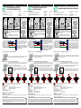
1- Inserire il servocomando sul perno della valvola di zona
2- Abbassare completamente la ghiera di bloccaggio
3- Ruotare la ghiera in senso orario no a raggiungere il necorsa
COLLEGAMENTI ELETTRICI
Esempio di collegamento del servocomando
all’alimentazione. Il cavo di colore blu va collegato
direttamente al neutro, il marrone ed il nero al
termostato ambiente. I cavi di colore rosso e verde
sono collegati rispettivamente al comune e al
normalmente aperto di un microinterruttore ausiliario.
NB: Per invertire il senso di rotazione del
servocomando e commutare quindi il segnale
da normalmente aperto a normalmente chiuso, è
sufciente invertire il collegamento del cavo nero
con quello marrone.
MTA
FASE
NEUTRO
VERDE
ROSSO
NERO
MARRONE
BLU
123Il motore può essere installato
sulla valvola in due diverse
posizioni senza alcuna differenza.
Per stabilire se la valvola è in posizione di apertura
o chiusura una volta installata, bisogna vericare
attraverso la nestrella del corpo motore, la posizione
del perno interno di colore arancione:
- Valvola aperta se è presente il perno arancione.
- Valvola chiusa se non è presente il perno arancione
СЕРВОПРИВОД Напряжение питания:
Крутящий момент:
Угол поворота:
Уровень защиты:
Время поворота:
24V - 230V 50Гц
10Нм
90°
IP44
40с
1 – Установить привод на шток зонного клапана
2 – Опустить блокирующее кольцо
3 – Повернуть кольцо по часовой стрелке до щелчка
ЭЛЕКТРИЧЕСКИЕ СОЕДИНЕНИЯ
Пример подключения сервопривода к сети.
Голубой провод должен непосредственно
подключаться к нейтрали, коричневый и чёрный
к термостату. Красный и зелёный провода
подключаются к общей клемме и к нормально
открытому внутреннему переключателю.
NB: Для реверса вращения сервопривода и
перевода режима включения с «нормально
открытого» на «нормально закрытое»
поменяйте местами соединение чёрного и
коричневого провода.
MTA
ФАЗА
НЕЙТРАЛЬ
ЗЕЛЁНЫЙ
КРАСНЫЙ
ЧЁРНЫЙ
КОРИЧНЕВЫЙ
ГОЛУБОЙ
ART.307075 - 307175 - 307077 - 307177 VÀLVULA DE ZONA 2 VÍAS
SERVOMOTOR Tensión de alimentación:
Fuerza motriz:
Angulo de rotación:
Grado de protección:
Tiempo de rotación:
24V - 230V 50Hz
10Nm
90°
IP44
40s
1- Insertar el servomotor sobre el eje de la válvula de zona
2- Bajar completamente la tuerca de blocaje
3- Girar la tuerca en sentido horario hasta alcanzar el nal de carrera
Ejemplo de conexión del servomotor a la
alimentación. el cable de color azul va conectado
directamente al neutro, el marrón y el negro al
termostato de ambiente. Los cables de color rojo y
verde van conectados respectivamente al común y al
normalmente abierto de un microruptor auxiliar.
NOTA: Para invertir el sentido de rotación del
servomotor y cambiar la señal de normalmente
abierto a normalmente cerrado, es suciente
invirtiendo la conexión del cable negro con el
marrón.
CONEXIÓN ELÉCTRICA
MTA
FASE
NEUTRO
VERDE
ROJO
NEGRO
MARRON
AZUL
123El motor puede ser instalado en
la válvula en dos posiciones sin
ninguna diferencia
Para averiguar si la válvula se encuentra en posición de
apertura o cierre una vez instalada, debemos vericarlo
en la apertura del cuerpo motor, la posición del perno en
color naranja:
-Válvula abierta si el perno está naranja
-Válvula cerrada si no esta la marca naranja del perno
123Сервопривод может быть
установлен на кран в любой из
двух позиций, на работу это не
влияет
После установки сервопривода на клапан положение
сферы (отк./закр.) можно определить через отверстие
на корпусе сервомотора по внутренней оранжевой
метке:
- кран открыт: оранжевая метка видна.
- кран закрыт: оранжевая метка не видна.
DIRETTIVA 2002/96/CE SUI RIFIUTI DI APPARECCHIATURE ELETTRICHE ED ELETTRONICHE
La direttiva comunitaria 2002/96/CE sui RAEE (riuti di apparecchiature elettriche ed elettroniche) prevede che
sia vietato smaltire qualsiasi tipo di RAEE come riuto solido urbano ma debba essere obbligatoriamente gestito
separatamente. Per il corretto smaltimento dei RAEE occorre rivolgersi alle autorità locali che informeranno sulle
modalità e procedure da seguire, nonchè sul luogo e sugli orari per i quali dovrà essere conferito il riuto.
DICHIARAZIONE DI CONFORMITA’
La FAR Rubinetterie dichiara sotto la propria responsabilità che i servomotori sono conformi alle direttive comunitarie:
2004/108/CE e 2006/95/CE.
DECLARACIÓN DE CONFORMIDAD
Far Rubinetterie SpA declara bajo responsabilidad propia que los servomotores son conformes a las directivas comunitarias:
2004/108/CE y 2006/95/CE
DIRECTIVA 2002/96/CE SOBRE RESIDUOS DE APARATOS ELÉCTRICOS Y ELECTRÓNICOS
La directiva comunitaria 2002/96/CE sobre RAEE (residuos de aparatos eléctricos y electrónicos) prevee que
este prohibido deshacerse de cualquier tipo de RAEE como residuo sólido urbano, y tiene que ser obligatoriamente
gestionado separadamente. Para el correcto rechazo de los RAEE hay que dirigirse a las autoridades locales que
informaran sobre el proceso a seguir, así como del lugar y el horario donde entregar el residuo.
VÁLVULA DE ZONA MOTORIZADA CON
ENSAMBLAJE RÁPIDO
МОТОРИЗОВАННЫЕ ЗОННЫЕ КРАНЫ
С БЫСТРОРАЗЪЁМНЫМ СОЕДИНЕНИЕМ
ДИРЕКТИВА 2002/96/CE ПО УТИЛИЗАЦИИ ЭЛЕКТРИЧЕСКОГО И ЭЛЕКТРОННОГО ОБОРУДОВАНИЯ
Директива 2002/96/CE ‘RAEE’ (утилизация электрического и электронного оборудования) устанавливает,
что они на могут трактовать как твёрдые бытовые отходы и должны перерабатываться отдельно. Для
правильной утилизации ‘RAEE’ следует обратиться к местным органам управления, которые располагают
информацией о соответствующих методах и процедурах, а также местах и времени утилизации.
ДЕКЛАРАЦИЯ СООТВЕТСВИЯ
FAR Rubinetterie S.P.A. информирует, что сервомоторы соответствуют европейским стандартам 2004/108CE и 2006/95/CE.

TECHNICAL FEATURES
ART.307075 - 307175 - 307077 - 307177 2-WAY ZONE VALVE
FAR Rubinetterie S.p.A. - www.far.eu
Instructions
ART.307080 - 307180 - 307082 - 307182 3-WAY DIVERTER ZONE VALVE
Pic.1
90° Rotation
Pic.2
90° Rotation
The illustration shows how the position of the ball permits the inlet of uid from below and then diverts it to the right. In the
same position it can permit uid to enter from the right and then divert it downwards.
Before installing the actuator, it is essential to check that the ow aperture in the
ball of the valve is positioned in the desired direction. The valve can be adjusted
by means of a screwdriver. The silk-screen printing on the control stem shows
the position of the ball.
The zone valve features a special anti-blockage system inside, which prevents the valve blocking
in even the worst operating conditions. All models of zone valve feature this system.
GB
: UNI EN 12165:11 CW617N Brass
: Anti-blockage system with OR in EPDM and seats in PTFE
: UNI EN 12164:11 CW614N Brass
: 16 bar
: 5 bar
: -5 °C (with antifreeze) +100 °C
: water, water with glycol
Valve body and ball
Sealing gaskets
Control stem
Nominal working pressure
Differential maximum pressure
Circulating uid temperature
Usable uids
TECHNISCHE DATEN
: Messing UNI EN 12165:11 CW617N
: Antiblockiervorrichtung mit OR aus EPDM und Sitze aus PTFE
: Messing UNI EN 12164:11 CW614N
: 16 bar
: 5 bar
: -5 °C (mit Frostschutz) +100 °C
: Wasser und Wasser mit Glykol
Ventilgehäuse und Kugel
Dichtung
Einstellbolzen
Betriebs-Nenndruck
Maximaler Differenzialdruck
Flüssigkeitstemperatur
Zugelassene Flüssigkeiten
ART.307075 - 307175 - 307077 - 307177 2-WEGE-ZONENVENTIL
ART.307080 - 307180 - 307082 - 307182 3-WEGE-ZONENVENTIL MIT ABLEITFUNKTION
Abb.1
Drehung um 90°
Abb.2
Drehung um 90°
FAR Rubinetterie S.p.A. - www.far.eu
Anleitung
D
Das Zonenventil ist im Innenbereich mit einem Blockierungsschutz ausgestattet, der auch unter
schwierigsten Betriebsbedingungen ein Klemmen der Kugel verhindert. Mit dieser Vorrichtung
sind alle Zonenventil-Typen ausgerüstet.
In diesem Fall ist an der Anzeige ersichtlich, dass die Kugel den Einlauf der Flüssigkeit von unten nach rechts ermöglicht.
Der Einlauf der Flüssigkeit kann auch von rechts nach unten erfolgen.
Vor der Installation der Servosteuerung muss die Stellung des Anzeigers am
Kugelloch überprüft werden, um sicherzustellen, dass er in die gewünschte
Richtung gebracht wurde. Das Ventil kann mithilfe eines Schraubenziehers
geregelt werden. Die Markierung am Einstellbolzen zeigt die Stellung der Kugel.
CARACTÉRISTIQUES TECHNIQUES
ART.307075 - 307175 - 307077 - 307177 VANNE DE ZONE À 2 VOIES
FAR Rubinetterie S.p.A. - www.far.eu
Mode d’emploi
ART.307080 - 307180 - 307082 - 307182 VANNE DE ZONE DÉVIATRICE À 3 VOIES
Fig.1
Rotation de 90°
Fig.2
Rotation de 90°
Dans ce cas, l’indicateur montre que la position de la bille permet l’entrée du uide du bas vers la droite. L’entrée du uide
peut au contraire se produire de la droite vers le bas.
Avant d’installer le servomoteur il faut s’assurer que l’indicateur du trou de la
bille se trouve dans la direction voulue. La vanne peut être réglée à l’aide d’un
tournevis. Le marquage sur la tige de commande indique la position de la bille.
La vanne de zone intègre un système antiblocage qui permet d’éviter le blocage de la bille même
dans situations d’exercice les plus difciles. Ce système est incorporé dans toutes les vannes de
zone, quelqu’en soit le type.
F
: Laiton UNI EN 12165:11 CW617N
: Dispositif antiblocage avec O-ring en EPDM et siège en PTFE
: Laiton UNI EN 12164:11 CW614N
: 16 bars
: 5 bars
: -5 °C (avec antigel) +100 °C
: eau et eau avec glycol
Corps vanne et bille
Garniture
Tige de commande
Pression nominale d’exercice
Pression différentielle maximale
Température du uide circulant
Fluides admis
VANNES DE ZONE MOTORISEE A RACCORD RAPIDE
3-Way zone valve with “L” passage is a diverter valve with uid inlet from below and uid delivery
to the thermal carrier towards right or left as a function of the position of actuator (Pic.1); or
entering from right or left and diverted towards the centre (Pic.2).
This valve is ideal for the commutation of the system, depending on the change of seasons.
Das Dreiwege-Zonenventil mit L-Anschluss ist ein Ableitventil mit Einlauf auf der unteren Seite und
Auslauf der wärmetragenden Flüssigkeit nach links oder nach rechts, abhängig von der Stellung
des Stellantriebs (Abb.1), oder umgekehrt von rechts bzw. links nach unten (Abb.2). Dieses Ventil
eignet sich für die Umschaltung vom Sommer- auf den Winterbetrieb und umgekehrt.
La vanne à trois voies avec passage à L est une vanne déviatrice avec entrée au- dessous
et renvoi du uide caloporteur vers la droite ou vers la gauche, en fonction de la position du
servomoteur (g.1), ou au contraire de la droite ou la gauche vers le bas (g.2). Cette vanne est
indiquée pour le passage de la modalité hiver à la modalité été et vice-versa.
ACTUATOR Feed voltage:
Torque:
Rotation angle:
Protection level:
Rotation time:
24V - 230V 50Hz
10Nm
90°
IP44
40s
1- Place the actuator on the stem of the zone valve
2- Lower the locking ring
3- Turn the ring clockwise up to the end of the stroke
ELECTRICAL CONNECTIONS
Example of an actuator connection to a terminal. The
blue wire must be connected directly to neutral, the
brown and the black to the thermostat. The red and
the green wires must be connected to the common
contact and to a N.O. auxiliary microswitch.
NB: To reverse the rotation of the actuator , and
then switch the signal from ‘normally open’ to
‘normally closed’, reverse the connection of the
black wire with the brown.
MTA
PHASE
NEUTRAL
GREEN
RED
BLACK
BROWN
BLUE
123The actuator can be installed on
the valve in either two positions
with no impact on operation.
Once the valve is installed, the opening or closing
position can be determined through the aperture on the
actuator body by checking the position of the internal
orange pin:
- Open valve: when the orange pin is visible.
- Closed valve: when the orange pin is not visible.
SERVOSTEUERUNG Netzspannnung:
Drehmoment:
Drehwinkel:
Schutzgrad:
Drehzeit:
24V - 230V 50Hz
10Nm
90°
IP44
40s
1- Die Servosteuerung auf den Bolzen des Zonenventils stecken
2- Den Arretierring vollständig nach unter schieben
3- Den Arretierring im Uhrzeigersinn bis zum Anschlag drehen
Beispiel für den Anschluss der Servosteuerung an die
Stromversorgung. Das blaue Kabel muss direkt mit
dem Neutralleiter verbunden werden, das braune und
das schwarze Kabel mit dem Umgebungsthermostat.
Das rote und das grüne Kabel werden jeweils mit dem
gemeinsamen Leiter und mit dem Arbeitskontakt des
Mikrohilfsschalters verbunden.
Bitte beachten Sie: Um die Drehrichtung der
Servosteuerung umzukehren und folglich das
Signal von Arbeitskontakt auf Ruhekontakt
umzuschalten, ist es ausreichend, die
Verbindungen des schwarzen Kabels mit denen
des braunen auszutauschen.
ELEKTRISCHE VERBINDUNGEN
MTA
PHASE
NEUTRAL
GRÜN
ROT
SCHWARZ
BRAUN
BLAU
123Der Motor kann auf dem
Ventil in zwei verschiedenen
Positionen installiert werden, die
unterschiedslos verwendet werden
können.
Um festzustellen, ob das bereits installierte Ventil
offen oder geschlossen ist, muss man die Stellung des
orangefarbenen Bolzens im Innenbereich durch das
Inspektionsfenster im Motorengehäuse überprüfen:
-Ventil offen, wenn der orangefarbene Bolzen sichtbar ist.
-Ventil geschlossen, wenn der orangefarbene Bolzen
nicht sichtbar ist.
SERVOMOTEUR Type de servomoteur:
Couple moteur:
Angle de rotation:
Degré de protection:
Temps de rotation:
24V - 230V 50Hz
10Nm
90°
IP44
40s
1- Insérer le servomoteur sur le pivot de la vanne de zone
2- Baisser complètement le collier de blocage
3- Tourner le collier dans le sens des aiguilles d’une montre jusqu’en butée
BRANCHEMENTS
Exemple de branchement du servomoteur à
l’alimentation. Le câble bleu doit être raccordé
directement au neutre, le marron et le noir au thermostat
ambiant. Les câbles rouge et vert sont raccordés,
respectivement, au contact commun et au contact
normalement ouvert d’un micro-interrupteur auxiliaire.
NB : Pour inverser le sens de rotation du
servomoteur et commuter donc le signal de
normalement ouvert à normalement fermé, il suft
d’inverser le raccordement du câble noir par celui
du câble marron.
MTA
PHASE
NEUTRE
VERT
ROUGE
NOIR
MARRON
BLEU
123Le moteur peut être installé sur
la vanne dans deux positions
différentes, sans aucune différence.
Pour établir si la vanne est en position d’ouverture ou de
fermeture après installation, il faut vérier la position du
pivot interne couleur orange à travers la petite fenêtre
du corps moteur :
- Vanne ouverte, si le pivot orange est présent
- Vanne fermée, si le pivot orange n’est pas présent
DECLARATION OF CONFORMITY
FAR Rubinetterie SpA under its own responsibility declares that actuators are produced in conformity to the EEC standards:
2004/108CE and 2006/95CE.
KONFORMITÄTSERKLÄRUNG
FAR Rubinetterie SpA erklärt unter eigener Verantwortung, dass die Stellantriebe folgender EU-Richtlinien entsprechen:
2004/108/CE und 2006/95/CE.
The 2002/96/CE directive on the ‘RAEE’ (waste from electrical and electronic equipment) states that they cannot
be treated like the municipal solid waste, but must be managed separately. In order to carry out a correct recovery
of the ‘RAEE’, apply to the local authority, which will have information about methods and procedures to follow, as
well as about place and time for the waste delivery.
EU-RICHTLINIE 2002/96/EG BEZÜGLICH ABFALL VON ELEKTRISCHEN UND ELEKTRONISCHEN GERÄTEN
Nach der europäischen WEEE-Richtlinie 2002/96/EG (Elektro-und Elektronikaltgeräte) ist eine Entsorgung von allen
WEEE-Altgeräten über Restmüll verboten. Die entsprechenden Altgeräte sind getrennt zu entsorgen. Für die einwandfreie
Entsorgung der WEEE-Geräte wenden Sie sich bitte an die zuständigen Behörden, die Ihnen Informationen über das
entsprechende Entsorgungsverfahren sowie über den Ort und die Zeiten zur Entsorgung der Altgeräte liefern werden.
MOTORIZED ZONE VALVES WITH
QUICK-COUPLING INSTALLATION
MOTORISIERTE ZONENVENTILE MIT
SCHNELLKUPPLUNG
DIRECTIVE 2002/96/CE SUR LES DECHETS D’EQUIPEMENTS ELECTRIQUES ET ELECTRONIQUES (DEEE)
Conformément à la directive communautaire 2002/96/CE sue les déchets d’équipements électrique et
électroniques, les DEEE ne doivent pas être éliminés comme déchets municipaux solides, mais être traités
séparément. Pour connaître les modalités et les procédures à suivre pour une bonne élimination des DEEE, ainsi
que le lieu et les horaires de collecte des déchets, il convient de s’adresser aux autorités locales.
DECLARATION DE CONFORMITE
La société FAR Rubinetterie S.p.A. déclare, sous sa responsabilité, que ses servomoteurs sont conformes aux directives
communautaires 2004/108/CE et 2006/95/CE.
2002/96/CE DIRECTIVE FOR THE RECOVERY OF WASTE FROM ELECTRICAL AND ELECTRONIC EQUIPMENT
-
 1
1
-
 2
2


in altre lingue
- français: Far V3PZV1 Guide d'installation
- español: Far V3PZV1 Guía de instalación
- Deutsch: Far V3PZV1 Installationsanleitung
Altri documenti
-
Giacomini R140C Istruzioni per l'uso
-
-
-
Caleffi 526142 Manuale utente
-
-
-
-
-
-