CAME FLEX 119RID158 Manuale del proprietario
- Tipo
- Manuale del proprietario

CANCELLI AU TO MA TI CI
Documentazione
Tecnica
M01
rev. 0.1
12/03
©
CAME
CANCELLI
AUTOMATICI
119DM01
B= 210
C min
cor sa=350
C max
corsa=115
B= 235
A= 100
A= 40
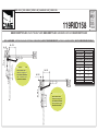
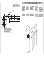
ASSI & INGOMBRI | CENTRE LINES AND EXTERNAL DIMENSIONS | AXES ET ENCOMBREMENTS | ACHSEN & ABMESSUNGEN | EJES Y DIMENSIONES MÁXIMAS
LARGHEZZA ANTA PESO ANTA
GATE WING WIDTH GATE WING WEIGHT
LARGEUR VANTAIL POIDS VANTAIL
TORFLÜGELBREITE
TORFLÜGELGEWICHT
ANCHO PUERTA PESO PUERTA
m. Kg.
0,80 150
1,20 125
1,60 100
A C
40÷100 0÷150
BRACCIO DRITTO FLEX / FLEX STRAIGHT ARM / BRAS DROIT FLEX / GERADER ARM FLEX / BRAZO RECTO FLEX
119RID158
SERIE FLEX | FLEX SERIES | SÊRIE FLEX | BAUREIHE FLEX | SERIE FLEX
Disassamento min.
Minimum misalignment
Excentration minimum
Min. Fluchtabweichung
Desalineado mínimo
C
min=0
B
= 210
Disassamento max.
Maximum misalignment
Excentration maximum
Max. Fluchtabweichung
Desalineado máximo
C
max=150
B
= 235

56
12
20
80
3 x ø 8,5
56
400
20
3 x M6
50
50150150
15
24
12
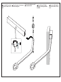
Guida di scorrimento braccio diritto
Travel guide for straight arm
Glissière de coulissement bras droit
Führungsschiene für geraden Arm
Guía de deslizamiento brazo recto
Flangia attacco motoriduttore
Gear motor mounting ange
Bride de raccord du motoréducteur
Getriebemotorbefestigungs-Flansch
Brida anclaje motorreductor
1 Tracciare
gli assi e gli
ingombri
del l’in sie me
tenendo con-
to dello sche-
ma a pag. 2,
quindi s sa re
la angia di
an co rag gio
del motoridut-
tore al muro
o al pi la stro.
Descrizione fasi - Steps description - Description des phases - Reschreibung der Montagevorgänge - Descripción fases
ISTRUZIONI DI MONTAGGIO | ASSEMBLY INSTRUCTIONS | INSTRUCTIONS POUR LE MONTAGE
MONTAGEANLEITUNG | INSTRUCCIONES DE MONTAJE
1 Trace the
axes and the
dimensions of
the assembly,
taking account
of the diagrams
on page 2; then
secure the an-
choring ange of
the gearmotor to
the wall or to the
pillar.
1 Tracer les axes
et les encom-
brements de
l’ensemble en
tenant compte
des schémas
à la page 2 et
xer la bride
d’ancrage du
motoréducteur
au mur ou au
pilier.
1 Die Achsen
und den Raum-
bedarf der
Einheit festlegen
und dabei die
Pläne auf Seite 2
berücksichtigen;
danach den Ver-
ankerungs ansch
des Getriebemo-
tors an der Wand
oder am Pfeiler
befestigen.
1 Marque los
ejes y las di-
mensiones del
conjunto tenien-
do en cuenta los
esquemas de
pág.2, entonces
je la brida de
sujeción del mo-
torreductor a la
pared o al pilar

2 Fissare la guida di scorrimen-
to all'anta e inserire il braccio
dritto.
2 Secure the runner to the wing and
insert the straight arm.
2 Fixer le rail de guidage au vantail
et monter le bras droit.
2 Die Laufschiene am Türügel
befestigen und den geraden Arm
einführen.
2 Fije la guía de deslizamiento
a la hoja e introduzca el brazo
recto.

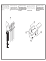
5 Assemblare il braccio diritto (D)
alla boccola intermedia solidale
all’albero del motoriduttore e s-
sare il braccio tramite i grani M8
(C) e M4 (E);
D
C
C
E
E
5
Assemble the straight arm (D) to
the intermediate bushing integral to
the gearmotor shaft, and secure the
arm with grub-screws M8 (C) and M4
(E);
5
Assembler le bras droit (D) à la
douille intermédiaire solidaire de
l’arbre du motoréducteur et xer le
bras à l’aide des vis sans tête M8
(C) et M4 (E) ;
5
Den geraden Arm (D) an die fest
mit der Getriebemotorwelle verbun-
denen Zwischenbüchse montieren
und den Arm mit den Stiften M8 (C)
und M4 (E) befestigen;
5
Ensamble el brazo recto (D) al
casquillo intermedio solidario al
árbol del motorreductor y je el
brazo con los tornillos sin cabeza
M8 (C) y M4 (E);
-
 1
1
-
 2
2
-
 3
3
-
 4
4


