Pepperl+Fuchs RL28-8-H-2000-IR-Z/49/116 Istruzioni per l'uso
- Tipo
- Istruzioni per l'uso

alle Maße in mm
Dimensions
Abmessungen
Technische Daten
Technical data
Elektrischer Anschluss
Electrical connection
Adressen/Addresses
Sicherheitshinweise:
• Vor der Inbetriebnahme Betriebsanleitung lesen
• Anschluss, Montage und Einstellung nur durch Fachpersonal
• Kein Sicherheitsbauteil gemäß EU-Maschinenrichtlinie
Security Instructions:
• Read the operating instructions before attempting commissioning
• Installation, connection and adjustments should only be undertaken by specialist personnel
• Not a safety component in accordance with the EU Machinery Directive
all dimensions in mm
www.pepperl-fuchs.com
Pepperl+Fuchs GmbH
68301 Mannheim · Germany
Tel. +49 621 776-4411
Fax +49 621 776-27-4411
Worldwide Headquarters
Pepperl+Fuchs GmbH · Mannheim · Germany
USA Headquarters
Pepperl+Fuchs Inc. · Twinsburg · USA
E-mail: fa-info@us.pepperl-fuchs.com
Asia Pacific Headquarters
Pepperl+Fuchs Pte Ltd · Singapore
Company Registration No. 199003130E
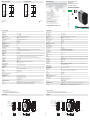
Empfänger
Sender
Typenschild
Hell-/Dunkel-Schalter
Tastweiteneinsteller
LED-Schaltzustand
LED-Schaltzustand
LED-Betriebsanzeige
Schwalbenschwanz-
aufnahme
DIP-Schalter
Zeiteinsteller
für GAB und IAB
Zeiteinsteller
für GAN
interne Verbindung
interne Verbindung
DIP-Schalter
16
9.6
25.8
2
25
66211
5
63
88
65.5
26
ø5
26.5
8
5
4
3
2
1
8
7
6
GY
BU
BU
OG
OG
GY
GY
GY
ON
4
3
2
1
OFF
Reflexions-Lichttaster HGA
mit Klemmraum
Background suppression sensor
with terminal compartment
RL28-8-H-2000-IR-Z/49/116
Allgemeine Daten
Tastbereich 20 ... 2000 mm
Tastbereich min. 20 ... 200 mm
Tastbereich max. 20 ... 2000 mm
Hintergrundausblendung max. + 10 % der oberen Tastbereichsgrenze
Lichtsender IRED
Lichtart infrarot, Wechsellicht , 880 nm
Schwarz-/Weiß-Differenz (6%/90%) < 40 %
Lichtfleckdurchmesser ca. 70 mm im Abstand von 2000 mm
Öffnungswinkel Sender 2°,
Empfänger 2°
Fremdlichtgrenze 50000 Lux
Kenndaten funktionale Sicherheit
MTTFd 720 a
Gebrauchsdauer (TM) 20 a
Diagnosedeckungsgrad (DC) 0 %
Anzeigen/Bedienelemente
Betriebsanzeige LED grün
Funktionsanzeige 2 LEDs gelb
ein: Objekt innerhalb des Tastbereiches\aus: Objekt außerhalb des Tastbereiches
Bedienelemente Tastweiteneinsteller , Hell-/Dunkel-Umschalter
Elektrische Daten
Betriebsspannung UB10 ... 30 V DC
Welligkeit 10 %
Leerlaufstrom I0
40 mA
Ausgang
Schaltungsart hell-/dunkelschaltend, umschaltbar (Dabei ist der eine H/D-Umschalter nur dann in Funktion,
wenn sich der jeweils andere in der Stellung "dunkelschaltend" befindet.)
Signalausgang 1 NPN, 1 PNP gleichschaltend, kurzschlussfest, verpolgeschützt , offene Kollektoren
Schaltspannung max. 30 V DC
Schaltstrom max. 200 mA
Schaltfrequenz f 250 Hz
Ansprechzeit 2 ms
Timerfunktion GAN, GAB, IAB, GAN-IAB, GAN-GAB, programmierbar
Einstellbereich 0,02 ... 1 s
Umgebungsbedingungen
Umgebungstemperatur -40 ... 60 °C (-40 ... 140 °F)
Lagertemperatur -40 ... 75 °C (-40 ... 167 °F)
Mechanische Daten
Schutzart IP67
Anschluss Klemmraum mit 8 Federzugklemmen für Aderquerschnitt 0,5 ... 1,5 mm2, Abisolierung 7,5 ... 8,5
mm, Kabelverschraubung M16x1,5
Material
Gehäuse Kunststoff ABS
Lichtaustritt Kunststoffscheibe
Masse 112 g
Normen- und Richtlinienkonformität
Richtlinienkonformität
EMV-Richtlinie 2004/108/EG EN 60947-5-2:2007 + A1:2012
Normenkonformität
Produktnorm EN 60947-5-2:2007 + A1:2012
IEC 60947-5-2:2007 + A1:2012
Normen UL 60947-5-2: 2014
EN 62471:2008
Zulassungen und Zertifikate
Schutzklasse II, Bemessungsspannung
250 V AC bei Verschmutzungsgrad 1-2 nach IEC 60664-1
Achtung !
Die Schutzklasse 2 ist nur gültig bei geschlossenem Klemmraum.
UL-Zulassung E87056 , cULus Listed , "Class 2"-Netzteil , Type Rating 1
Receiver
Transmitter
Name plate
Light/dark switch
Sensing range adjuster
LED-switch status
LED-switch status
LED-operating display
Dovetail mount
DIP-switch
Indicator of detection range
for OFF delay and one shot
Indicator of detection range
for ON delay
Internal connection
Internal connection
DIP-switch
16
9.6
25.8
2
25
66211
5
63
88
65.5
26
ø5
26.5
8
5
4
3
2
1
8
7
6
GY
BU
BU
OG
OG
GY
GY
GY
ON
4
3
2
1
OFF
11/12/2015
Date: DIN A3 -> DIN
Option:
Q1
Q2
n.c.
n.c
GY
GY
GY
GY
BU
BU
OG
OG
0 V
+UB
/49
Option:
Q1
Q2
n.c.
n.c
GY
GY
GY
GY
BU
BU
OG
OG
0 V
+UB
/49
General specifications
Detection range 20 ... 2000 mm
Detection range min. 20 ... 200 mm
Detection range max. 20 ... 2000 mm
Background suppression max. + 10 % of the upper limit of the detection range
Light source IRED
Light type modulated infrared light , 880 nm
Black/White difference (6 %/90 %) < 40 %
Diameter of the light spot approx. 70 mm at a distance of 2000 mm
Angle of divergence transmitter 2°
receiver 2°
Ambient light limit 50000 Lux
Functional safety related parameters
MTTFd 720 a
Mission Time (TM) 20 a
Diagnostic Coverage (DC) 0 %
Indicators/operating means
Operation indicator LED green
Function indicator 2 LEDs yellow
ON: object inside the scanning range
OFF: object outside the scanning range
Control elements Detection range adjuster , Light/Dark switch
Electrical specifications
Operating voltage UB10 ... 30 V DC
Ripple 10 %
No-load supply current I0
40 mA
Output
Switching type light/dark on, switchable (selectable, light/dark switching is only activated if the receiver has 'dark
on' selected.)
Signal output 1 NPN, 1 PNP synchronized-switching, short-circuit protected, reverse polarity protected , open
collectors
Switching voltage max. 30 V DC
Switching current max. 200 mA
Switching frequency f 250 Hz
Response time 2 ms
Timer function ON delay (GAN), OFF delay (GAB), one shot (IAB), ON delay-one shot (GAN-IAB), ON delay-
OFF delay (GAN-GAB), programmable
adjustment interval 0.02 s ... 1 s
Ambient conditions
Ambient temperature -40 ... 60 °C (-40 ... 140 °F)
Storage temperature -40 ... 75 °C (-40 ... 167 °F)
Mechanical specifications
Degree of protection IP67
Connection terminal compartment with 8 spring-loaded terminals for wire cross section 0.5 ... 1.5 mm2, insu-
lation stripping 7.5 ... 8.5 mm, M16 x 1.5 cable gland
Material
Housing Plastic ABS
Optical face Plastic pane
Mass 112 g
Compliance with standards and directives
Directive conformity
EMC Directive 2004/108/EC EN 60947-5-2:2007 + A1:2012
Standard conformity
Product standard EN 60947-5-2:2007 + A1:2012
IEC 60947-5-2:2007 + A1:2012
Standards UL 60947-5-2: 2014
EN 62471:2008
Approvals and certificates
Protection class II, rated voltage
250 V AC with pollution degree 1-2 according to IEC 60664-1
Caution!
The protection class 2 is only valid when the terminal compartment is closed.
UL approval E87056 , cULus Listed , class 2 power supply , type rating 1
= Hellschaltung
= Dunkelschaltung
= Light on
= Dark on
A7
Part. No.: 421276 45-0424F
Doc. No.:

Bestimmungsgemäße Verwendung:
Beim Reflexionslichttaster mit Hintergrundausblendung befinden sich Sender und
Empfänger in einem Gehäuse. Durch eine Winkelanordnung zwischen Sender
und Empfänger (2 Empfängerelemente) wird eine Ausblendung von Objekten au-
ßerhalb des Tastbereiches erreicht.
Die Erfassung von Objekten erfolgt unabhängig von deren Oberflächenstruktur,
Helligkeit und Farbe, sowie der Helligkeit des Hintergrundes.
Montagehinweise:
Die Sensoren können mit den Befestigungsschrauben direkt befestigt werden
oder über einen Haltewinkel (nicht im Lieferumfang).
Die Untergrundfläche muss plan sein, um Gehäuseverzug beim Festziehen zu
vermeiden. Es empfiehlt sich, die Mutter und Schraube mit Federscheiben zu si-
chern, um einer Dejustierung des Sensors vorzubeugen.
Justage:
Nach Anlegen der Betriebsspannung leuchtet die LED grün.
Sensor auf den Hintergrund ausrichten. Sollte die gelbe LED leuchten, ist der
Tastbereich mit Hilfe des Tastweiteneinstellers so zu reduzieren bis die gelbe LED
erlischt.
Objekterfassung:
Das zu erfassende Objekt in der gewünschten maximalen Tastweite platzieren
und den Lichtfleck darauf ausrichten. Wird das Objekt erfasst, leuchtet die gelbe
LED.
Leuchtet diese nicht, muss die Tastweite am Potentiometer so lange eingestellt
werden bis sie bei Objekterfassung leuchtet.
Reinigung:
Wir empfehlen in regelmäßigen Abständen die Optikfläche zu reinigen und Ver-
schraubungen, sowie die Anschlussverbindungen zu überprüfen.
Öffnen des Klemmraums
1)Um den Klemmraum zu öffnen wird ein flacher Schraubendreher benötigt. Der
Klemmraum befindet sich hinter dem schwarzen bedruckten Deckel. Setzen Sie
das Schraubendreher-Blatt in die Mittelkerbe unter dem LED Fenster. Schieben
Sie den Schraubendreher vollständig bis zum Anschlag in diese Kerbe ein.
2)Drücken Sie nun den Schraubendreher-Griff nach oben in Richtung zur Rich-
tung des LED Fensters.
3)Der bedruckte Deckel öffnet sich nach außen und außerhalb und gibt den
Klemmraum frei. Um den Klemmraum zu schließen, drücken Sie einfach den
Deckel in seine Ausgangsstellung zurück bis er einrastet.
Intended use:
The transmitter and receiver are located in the same housing for direct detection
sensors with background masking. Marking of objects outside the detection range
is achieved by arranging the angle between the transmitter and receiver (2 recei-
ver elements).
Objects are detected independently of their surface structures, brightness and co-
lour, as well as the brightness of the background.
Mounting instructions:
The sensors can be fastened directly with fixing screws or with a support bracket
(not included with delivery).
The surface underneath must be flat to prevent the housing from moving when it
is tightened into position. We recommend securing the nut and screw in place with
spring washers to prevent the sensor from going out of adjustment.
Adjustment:
After the operating voltage is applied, the LED is lit green.
Align the sensor to the background. If the yellow LED is lit, the detection range
should be reduced with the detection range adjuster until the yellow LED goes out.
Object detection:
Place the object to be detected at the desired maximum detection range and align
the light spot to it. If the object is detected, the yellow LED lights up.
If it does not light up, the detection range must be adjusted on the potentiometer
until it lights up when an object is detected.
Cleaning:
We recommend cleaning the optical surface and checking the screwed connection
and other connections at regular intervals.
Opening the terminal compartment
1)A flat-head screwdriver is needed to open the terminal compartment. Insert the
screwdriver into the center notch under the LED window next to the printed black
door with the blade all the way to back of this notch.
2)Push the screwdriver upward toward the direction of the LED.
3)The hinged door with printing will pivot outward, exposing the terminal compart-
ment. To close, simply push the hinged door to its original position so that it
snaps back into position.
X [m]
Y [mm] RL28-8-H-2000-IR
x
y
18 %
6 %
90 %
-15
-10
-5
0
5
10
15
0 500 1000 1500 2000 2500
Charakteristische Ansprechkurve
Courbe de response caractéristique
Curve di risposta caratteristica
Characteristic response curve
Curva de respuesta característica
Möglicher Abstand (Versatz) zwischen
optischer Achse und Referenzobjekt.
Permissible distance (offset) between
optical axis and reference target.
Ecart possible entre l'axe optique et la
cible de référence.
Desplazamiento entre el eje óptico y
objeto de referencia.
Distanza possibile (sfalsato) tra l'asse
ottico e l'ogetto di riferimento.
RL28-8-H-2000-IR
0
500
1000
1500
2000
2500
0500 1000 1500 2000 2500
Tastweitendifferenz
L'attenuation de la protée
Differenza dell' ampiezza di esplorazione
Difference detection distance
Differencia del rango de detección
x
18 %
6 %
90 %
eingestellte Tastweite x [mm]
Distance ΔX related to the focus point x [mm]
distance ΔX relative à la focale x [mm]
Distancia ΔX relativa al foco x [mm]
Distanza ΔX in relazione al fuoco x [mm]
gemessene Tastweite x [mm]
Measured detection distance x [mm]
Potée de détection mesurée x [mm]
Rango de detección medido x [mm]
Ampiezza di explorazione misurato x [mm]
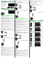
Einstellhinweise/adjustment instructions
Einstellhinweise/adjustment instructions
Zeitfunktionen
Fonctions de temporisation
Funzioni di temporizzazione
Timer functions
Funciones de tiempo
Zeitfunktion
Ohne
GAB
Dunkel
Hell
Dunkel
Hell
Dunkel
Hell
Schaltungsart Empfänger belichtet
Empfänger dunkel
EIN
AUS
EIN
AUS
EIN
AUS
EIN
AUS
EIN
AUS
GAN
IAB Dunkel
Hell
EIN
AUS
EIN
AUS
tAN
tAN tAN tAN
tAB
tAB
tIAB
tIAB tIAB tIAB
tIAB tIAB
tAB tAB
Die Zeit tAN, tAB und t IAB sind von 0,02 - 1 Sekunde einstellbar.
Der H/D-Schalter (Schalter links außen) ist in Stellung Dunkelschaltung dargestellt.
Timer function
Without
OFF delay
Dark
Light
Dark
Light
Dark
Light
Switching type Receiver exposed
Receiver dark
ON
OFF
ON
OFF
ON
OFF
ON
OFF
ON
OFF
ON delay
one shot Dark
Light
ON
OFF
ON
OFF
tON
tON tON tON
tOFF
tOFF
tOS
tOS tOS tOS
tOS tOS
tOFF tOFF
Time tON, tOFF and tOS are adjustab le from 0.02 to 1 seconds .
The Light-/Dark-Switch (Left, outer switch) is shown in the "Dark ON" position.
Fonction de temporisation
sans
GAB
foncé
clair
foncé
clair
foncé
clair
Mode de commutation Récepteur éclairé
Récepteur non éclairé
activé
désactivé
activé
désactivé
activé
désactivé
activé
désactivé
activé
désactivé
GAN
IAB foncé
clair
activé
désactivé
activé
désactivé
tAN
tAN tAN tAN
tAB
tAB
tIAB
tIAB tIAB tIAB
tIAB tIAB
tAB tAB
Les temps t
Le commutateur H/D (commutateur à l'extrême gauche) est représenté en position commutation obscur.
AN, tAB et tIAB sont réglables de 0,02 ... 1 s.
Función de tiempo
Sin
GAB
Oscuro
Claro
Oscuro
Claro
Oscuro
Claro
Modo de conmutación Receptor recibiendo luz
Receptor oscuro
GAN
IAB Oscuro
Claro
tAN
tAN tAN tAN
tAB
tAB
tIAB
tIAB tIAB tIAB
tIAB tIAB
tAB tAB
ON
OFF
ON
OFF
ON
OFF
ON
OFF
ON
OFF
ON
OFF
ON
OFF
El tiempo t
El conmutador H/D (conmutador exterior izquierdo) está representado en posición de recucción de la luz.
AN, tAB y tlAB es ajustable entre 0,02 y 1 segundos .
Funzione tempo
Senza
GAB
Scuro
Chiaro
Scuro
Chiaro
Scuro
Chiaro
Modo di commutazione Ricevitore illuminato
Ricevitore scuro
Un
Disattivo
Un
Disattivo
Un
Disattivo
Un
Disattivo
Un
Disattivo
GAN
IAB Scuro
Chiaro
Un
Disattivo
Un
Disattivo
tAN
tAN tAN tAN
tAB
tAB
tIAB
tIAB tIAB tIAB
tIAB tIAB
tAB tAB
i tempi t
L'interruttore chiaro/scuro (interruttore sul lato esterno sinistro) è rappresentato in posizione di azionamento in scuro.
AN, tAB e tIAB sono regolabili tra 0,02 s e 1 s.
ON
1234
ON
1234
ON
1234
ON
1234
ON
1234
ON
1234
ON
1234
ON
1234
ON
1234
ON
1234
ON
1234
ON
1234
ON
1234
ON
1234
ON
1234
ON
1234
ON
1234
ON
1234
ON
1234
ON
1234
-
 1
1
-
 2
2


Pepperl+Fuchs RL28-8-H-2000-IR-Z/49/116 Istruzioni per l'uso
- Tipo
- Istruzioni per l'uso
in altre lingue
Documenti correlati
-
Pepperl+Fuchs RL28-55-Z/49/76a/82b/116 Istruzioni per l'uso
-
-
-
-
-
-