Lindy HDBaseT Presentation System Manuale utente
- Categoria
- Interruttori video
- Tipo
- Manuale utente

© LINDY Group - FIRST EDITION (April 2020)
HDBaseT Presentation System with
Control Keypad
User Manual English
No. 38288
lindy.com
Tested to comply with
FCC Standards
For Home and Office Use!


!!! IMPORTANT !!!
Only use a direct Cat.5e/6/7 cable connection between the
HDBaseT ports. Do not connect these ports to Network or
Ethernet equipment or any active components
!!!! WICHTIG !!!!
Verwenden Sie AUSSCHLIEßLICH eine direkte
Kabelverbindung zwischen den HDBaseT Anschlüssen
aber NIEMALS eine Netzwerkverbindung oder Ethernet
oder irgendwelche aktiven Komponenten
!!! ATTENTION !!!
N'utilisez qu'une connexion par câble Ethernet directe
entre les ports, sans passer par le réseau Ethernet, un
commutateur ou un quelconque périphérique connecté à
votre réseau !
!!! IMPORTANTE !!!
UTILIZZATE UN CAVO DEDICATO PER LA CONNESSIONE
TRA LE DUE UNITA', NON COLLEGATELO AD UNA RETE
ETHERNET O AD ALTRI COMPONENTI ATTIVI

User Manual English
Safety Instructions
! WARNING !
Please read the following safety information carefully and always keep this document with
the product.
Failure to follow these precautions can result in serious injuries or death from electric
shock, fire or damage to the product.
Touching the internal components or a damaged cable may cause electric shock, which
may result in death.
This device is a switching type power supply and can work with supply voltages in the range 100 - 240
VAC For worldwide usability four different AC adapters are enclosed: Euro type, UK type, US/Japan type
and Australia/New Zealand type. Use the appropriate AC adapter as shown in the picture and ensure it
is firmly secured in place and does not detach by pulling before installing into a power socket.
To reduce risk of fire, electric shocks or damage:
▪ Do not open the product nor its power supply. There are no user serviceable parts inside.
▪ Only qualified servicing personnel may carry out any repairs or maintenance.
▪ Never use damaged cables.
▪ Do not expose the product to water or places of moisture.
▪ Do not use this product outdoors it is intended for indoor use only.
▪ Do not place the product near direct heat sources. Always place it in a well-ventilated place.
▪ Do not place heavy items on the product or the cables.
▪ Please ensure any adapters are firmly secured and locked in place before inserting into a wall socket

User Manual English
Introduction
Thank you for purchasing the HDBaseT Presentation System with Control Keypad. This product has been
designed to provide trouble free, reliable operation. It benefits from both a LINDY 2 year warranty and free
lifetime technical support. To ensure correct use, please read this manual carefully and retain it for future
reference.
The Lindy HDBaseT Presentation System is a multi-function AV solution which is ideal for creating smart,
autonomous presentation, education or collaboration spaces combining three core components. An
HDBaseT multi-AV transmitter, An HDBaseT receiver and a separate wall mounted room control panel.
Using reliable HDBaseT technology, single cable installation and PoH means this system is perfectly
suited for education in a classroom or training room environment
Package Contents
▪ HDBaseT Transmitter Wall Plate
▪ HDBaseT Receiver
▪ Control Panel
▪ 24V 3.75A Multi Country DC power Supply, Barrel Size: 5.5/2.1mm
▪ Quick Instruction Guide
Features
▪ Valens HDBaseT VS210 Chipset
▪ Distance:
▪ 4K, 30Hz, RGB, 8bit with 40m of Cat.6 cable
▪ 1920x1080, 60Hz, RGB, 8Bit with 70m of Cat.6 cable.
▪ HDMI 1.4b, HDCP 2.2 and HDCP 1.4 compliant.
▪ Up to 7.1 channels of High Definition audio pass through (LPCM, Dolby TrueHD, and DTS-HD Master
Audio).
▪ Supports multi-VESA Standard VGA formats input up to 1080p.
▪ Supports MIC input via terminal block.
▪ Stereo 30watts@4 ohms amplifier output (2 channel)
▪ Supports interactive display (Touch screen) USB control using USB HID.
▪ Control over Web GUI.
▪ Separate control panel for system control.
▪ Supports relay control.
▪ Supports RS-232 control.
▪ Colour: Transmitter: White, Receiver: Black, Control Plate: White
▪ ESD Protection: ± 8kV (air-gap discharge)
▪ Human Body Model: ± 4kV (contact discharge)
▪ Power Consumption: 75W max
▪ Operating Temperature 0°C - 40°C (32°F - 104°F)
▪ Storage Temperature -20°C - 60°C (-4°F - 140°F)
▪ Relative humidity: 20 – 90% RH (non condensing)
▪ CE/FCC and RoHS/REACH, California 65 compliant

User Manual English
Specification
• Transmitter wall plate:
• Input ports: 2x HDMI, 1x VGA, 1x Stereo Audio (3.5mm), 1x USB Type B Female
• Output ports: 1x HDBaseT, 1x RJ45 for RS232/Power (Control Plate connection)
• Control Ports: 1x Source Select Switch
• Dimensions: 115.9mm [W] x 38.7mm [D] x 114.3mm [H]
• Receiver:
• Input ports: 1x HDBaseT, 1x Mic, 1x LAN (RJ45), 1x USB Type A Female
• Output ports: 1x HDMI, 1x RS-232 (Screw Terminal), 1x Relay (Screw Terminal), 1x Audio
Out (Screw Terminal), 1x 2x30 Watts@4 ohms amplifier output (Screw Terminal)
• Dimensions: 250mm [W] x 104mm [D] x 30mm [H]
• Control Plate:
• Input / Output port: 1x RJ45 for RS232/Power
• Dimensions: 70mm [W] x 32mm [D] x 115mm [H]
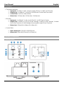
Installation and Operation
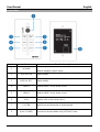
Transmitter Panel

User Manual English
Number
Name
Function Description
1
HDCP LED
HDCP status indicator.
▪ OFF: HDMI input is not carrying HDCP content.
▪ ON: HDMI input is carrying HDCP content.
2
LINK LED
HDBaseT Link status indicator.
▪ OFF: No Link.
▪ GREEN: Link successful.
▪ Blink GREEN: Link abnormal.
3
VGA LED
VGA signal indicator.
▪ OFF: There is no +5V HPD or VGA signal detected on the input.
▪ FLASHING: +5V HPD or VGA signal is detected.
▪ GREEN: VGA input is active and the VGA signal is detected.
4
POWER LED
System power indicator.
5
VGA IN
Connect to a VGA source.
6
AUDIO IN
Connect to an external audio source for the VGA signal.
7
HDMI 1 LED
HDMI 1 signal indicator.
▪ OFF: There is no +5V HPD or HDMI signal detected on the
input.
▪ FLASHING: +5V HPD or HDMI signal is detected.
▪ GREEN: HDMI input is active and the HDMI signal is detected.
8
HDMI 1 IN
Connect to an HDMI source device.
9
SOURCE
Press to switch between sources.
10
TO PC
Connect to the USB Host device, typically a PC
11
HDMI 2 LED
HDMI 2 signal indicator.
▪ OFF: There is no +5V HPD or HDMI signal detected on the
input.
▪ FLASHING: +5V HPD or HDMI signal is detected.
▪ GREEN: HDMI input is active and the HDMI signal is detected.
12
HDMI 2 IN
Connect to an HDMI source device.
13
HDBaseT OUT
Connect to the HDBaseT Receiver with a Cat5e/6/7 cable.

User Manual English
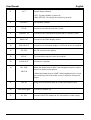
14
RS-232/POWER
Connect to the Control Panel via CAT5e/6/7 cable.
15
24VDC
(OPTIONAL)
This 24V / 1A connection is only used when the receiver doesn’t
provide power. The receiver included with 38288 provides power.
16
Micro-USB
For firmware updates.
17
DIP SWITCH
Used in combination with firmware updates. Please leave on the
default position.
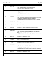
Receiver
Number
Name
Function Description
1
MIC GAIN
Adjust the MIC input gain. (Volume)
2
POWER LED
System power indicator.
3
LINK LED
HDBaseT Link status indicator.
▪ OFF: No Link.
▪ GREEN: Link successful.
▪ Blink GREEN: Link abnormal.
4
HDCP LED
HDCP status indicator.
▪ OFF: HDMI input is not carrying HDCP content.
▪ ON: HDMI input is carrying HDCP content.

User Manual English
5
ACT
System status indicator.
▪ OFF: System standby or power off.
▪ Blink GREEN: The system is functioning correctly.
6
SERVICE
For firmware updates.
7
TCP/IP
Connect to the LAN for web GUI control.
8
HDBaseT IN
Connect to the Transmitter Wall plate with a Cat5e/6/7 cable.
9
HDMI OUT
Connect to the HDMI display device.
10
USB DEVICE
Connect to an interactive display or USB sink device as required.
11
RS-232
RS-232 control for the display.
12
RELAY
To control the projector screen rise and fall.
13
AUDIO OUT
Connect to a speaker.
14
MIC LINE
SWITCH
When the switch is set to “MIC”, the microphone input is used to
connect a dynamic microphone.
▪ When the switch is set to “LINE”, the microphone input is used
for connecting a line level audio source or wireless microphone
output.
15
MIC IN
Using Phoenix terminal cable to connect microphone input
16
2X30 watts @4Ω
Connect to speaker out
17
DC 24V
Connect 24V/3.75A adaptor to AC wall outlet for power supply.

User Manual English
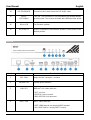
Control Plate
Number
Name
Function Description
1
VOLUME
Volume adjustment and LED indicator
Adjusts amplifier volume output
2
DISPLAY ON
Runs the DISPLAY ON routine, please see the full manual for
further details
3
DISPLAY OFF
Runs the DISPLAY OFF routine, please see the full manual for
further details.
4
HDMI 1
Selects HDMI 1 as the active source
5
HDMI 2
Selects HDMI 2 as the active source
6
VGA
Selects VGA as the active source
7
SYSTEM
Long press the button for 3 seconds to turn on or off the system,
please see the full manual for further details.
8
RJ45 / POWER
Connect to the transmitter using CAT5e/6/7 cable

User Manual English
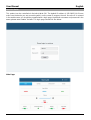
Web GUI Guide
This product can be controlled via it’s built in Web GUI. The default IP address is 192.168.2.100. Please
make sure the device you are connecting with is on the same IP range as the unit. Once the IP is entered
in the web browser you should be prompted with a login page, the default username and password is the
same, please enter “admin” for both. The login page should look like below:
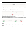
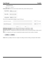
Main Page:

User Manual English
Input Select: You can choose from the available input options. It also shows the status of the input signal.
Green: The input port has an active signal.
Blue: The input port has a live connected device, but it is not an active signal.
Red: The input port has no signal.
Volume control adjusts the output for the amplifier and the audio extractor. Adjusting the slider will increase
or decrease volume for the amplifier and the audio extractor.
Mute toggle will silence the amplifier and the audio extractor outputs, however it does not silence the audio
on the HDMI output.
System: runs the system on/off subroutine when you switch the toggle. (see Routines at the end of the
manual)
Connection Status: indicates the connection status about the web server.
Display: Runs the display on/off subroutine when you switch the toggle, (see Routines at the end of the
manual)
Output Mute: when on, turns off the video output but it does not mute audio.

User Manual English
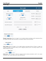
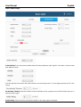
Control Page:
Display System Sync: When the toggle is in the ‘enable’ position, the display on/off subroutine will run
the system subroutine on/off every time. (see Routines at the end of the manual)
Auto System: When the toggle is in the ‘enable’ position, the system will turn off when no signals are
actively connected the amount of time can be configured, please see the “No Activity Timeout” in the
INPUT/CONTROL section.
Relay Sync: Sets the relays to either be triggered with the display subroutine on/off or the system
subroutine on/off. (see Routines at the end of the manual)

User Manual English
Relay (On) Time: Sets the amount of time that the relay contacts will stay closed.
The RS-232 communication settings for the RS-232 port.
RS232 On Command: Sends the string when the Display On subroutine is called.
RS232 Off Command: Sends the string when the Display Off subroutine is called.
CR + LF: Appends a carriage return and line feed character to the end of the input strings as they are sent
out.
Hex: The commands can be input as hexadecimal numbers when the Hex checkbox is marked.
Save: After any settings have been changed, the settings must be saved by pressing the ‘Save’ button.

User Manual English
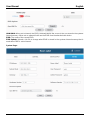
Input / Output Page:
Switch Mode: Sets how the transmitter plate will change between input signals. It includes an ‘Auto’ mode
and ‘Manual’ mode.
Sets the priority to use when the switch mode is set to priority mode. 1 is the highest priority and 3 is the
lowest.
No Activity Timeout: Sets the amount of time it will take for the system to turn itself off when there is no
detected input signal.
Audio Delay: Sets how many seconds the audio on the amp output is delayed.

User Manual English
HDMI EDID: When set to Internal, the EDID communicated to the source is the one stored in the systems
internal memory. When set on external it will use the EDID from the attached sink device.
EDID: The name of the current EDID.
EDID Update: Upload a .bin file to change what EDID is stored in the systems internal memory that is
used when EDID is set to internal.
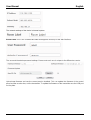
System Page:

User Manual English
The network settings of the device’s internal system.
Room Label: This is the customisable label that appears at the top of the web interface.
The user and the admin password settings. Please note each one is unique to the different accounts.
Upload new firmware and see the current version installed. This can update the firmware of the control
panel and the receiver box, not the transmitter. To update the firmware of the transmitter use the USB port
on the plate.

User Manual English
Troubleshooting
I have lost access to the system or it has strange behaviour.
To perform a system reset hold the transmitter source button (SOURCE button) for 20 seconds until the
HDCP light flashes three times. When the system is reset, user settings will return to their default values
this includes passwords, room label, switching mode, IP address, etc.
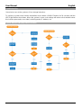
System ON/OFF & Display ON/OFF Routine

User Manual English
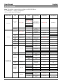
RS-232 Commands
Note: The default communication settings are 9600 8N1 None.
> - Command, ? - Query, () Response
<CR> = 0x0D Hex / 13 Decimal
Command Category
Action
Basic ASCII String
Variables
Example Settings
Example String
Example Response
Com Settings
Setup Baud
Rate
>BR:a,b,p<CR>
a = Baud rate
Set RS232 Baud
Rate to 9600 with 8
bits and No Parity
>BR:9600,8,N<CR>
(BR:9600,8,N)
(2400, 4800, 9600,
14400, 19200, 38400,
5600, 57600, 115200)
b=bits,
p=parity
(Even = E, Odd = O,
None = N)
Query Rs232
Com Setting
?RS<CR>
Request the Rs232
Setting
?RS<CR>
(Rs232, BR:9600,8,N)
IP Settings
IP Adressing
>IPA:m, ipa<CR>
m = Mode (S=Static,
D=Dynamic)
Set IP Adress to
static at
192.168.2.175
>IPA:S,192.168.2.175<CR>
(Static, 192.168.2.175)
ipa = IP Adress
Set The Unit to
Dynamic
>IPA:D<CR>
(Dynamic, 192.168.1.50)
Quary IP
Adress
?IPA<CR>
Request IP adress
?IPA<CR>
(Static,192.168.2.175)
(Dynamic, 192.168.1.20)
Set Subnet
Mask
>MASK:m<CR>
m = Mask
(XXX.XXX.XXX.XXX)
Set the mask to
255.255.255.0
>MASK:255.255.255.0<CR>
(Mask, 255.255.255.0)
Quary Subnet
Mask
?MASK<CR>
Request the subnet
mask
?MASK<CR>
(Mask, 255.255.255.0)
Set Gateway
>GATE:ipa<CR>
ipa = IP Adress
Set the Gateway to
192.168.1.1
>GATE:192.168.1.1<CR>
(Gateway, 192.168.1.1)
Quary
Gateway
?GATE<CR>
Request the
Gateway
?GATE<CR>
(Gateway, 192.168.1.1)
Input/Output and
switching Controls
Switching
Inputs to
Output
>SW:i<CR>
i = Input
Switch to (VGA and
Audio)
>SW:V<CR>
(VGA Active)
(V= VGA & Audio,
DP = DisplayPort
Switch to
DisplayPort
>SW:DP<CR>
(DP Active)
H (or H1, H2) = HDMI,
Switch to HDMI1
>SW:H1<CR>
(HDMI1 Active)
Switch to HDMI2
>SW:H2<CR>
(HDMI2 Active)
Query Active
Signal
?SW<CR>
Request the active
source
?SW<CR>
([Value] Active)
Mute the
Output Video
>VM:a<CR>
a = 0, 1, T
Unmute the Video
Output
>VM:0<CR>
(Video Output Mute Off)
0 = Unmute Video
Output
1 = Mute Video
Output
Mute the Video
Output
>VM:1<CR>
(Video Output Mute On)
T = Toggle
Toggle the Mute
>VM:T<CR>
(Video Output Mute [Off,
On])
Query Mute
Status
?VM<CR>
Request Video
Mute Status
?VM<CR>
(Video Output Mute [On,
Off])
Setting the
Front Panel
Select Button
mode
>PB:a<CR>
a = Button Status
Enable Front Panel
Button
>PB:1<CR>
(Button Enabled)
(0 = Disabled
1 = Enabled)
Disable Front Panel
Button
>PB:0<CR>
(Button Disabled)
2 = Rs232 Mode
Rs232 Mode
>PB:2<CR>
(Button Rs232 Mode)
Changing
Switch Modes
>SM:a<CR>
a = Switching Mode
Set Switch Mode to
Manual
>SM:M<CR>
(Manual Mode)
(M = Manual,
H = Hybrid,
Set Switch Mode to
Hybrid
>SM:H<CR>
(Hybrid Mode)锁定一个
接入的信号源

User Manual English
A = Auto,
Set Switch Mode to
Auto
>SM:A<CR>
(Auto Mode)
P = Priority)
Set Switch Mode to
Priority
>SM:P<CR>
(Priority Mode)
Query
switching
mode
?SM<CR>
Request active
mode
?SM<CR>
([value] Mode)
Setting Input
Priority
>SMP:[a,b,c]<CR>
Port prioritisation : "a"
the highest priority
followed by b and so
on for multiple inputs
Set the following
priority from
Highest to lowest;
HDMI1, HDMI2,
VGA
>SMP:[H1,H2,V]<CR>
(Priority [H1,H2,V])
(V = VGA & Audio,
DP = DisplayPort
(H1, H2) = HDMI
Query Port
Priority
?SMP<CR>
Request the
current Priority of
Inputs for Auto
Switching
?SMP<CR>
(Priority [H1,H2,V])
Audio Mode
>AUD:a<CR>
a = Audio Mode
Set the Unit to pass
embeded audio
>AUD:I<CR>
(Audio, Embedded)
(I=Embeded Audio, E =
External Input,
Set the unit to
Embed the external
input
>AUD:E<CR>
(Audio, External Input)
T = Toggle)
Toggle between
Embeded and
External
>AUD:T<CR>
(Audio, [Value])
Query Audio
Mode
?AUD<CR>
Request Audio
Mode
?AUD<CR>
([value] Mode)
Audio
Volume
Control
>VOL:a<CR>
a = +/-
Increase Audio
Volume
>VOL:+<CR>
(Volume value)
+ = Increase Vol
- = Decreaase Vol
Decrease Audio
Volume
>VOL:-<CR>
(Volume value)
>VOL:S,50<CR>
(Volume value)
?VOL<CR>
(Volume value)
Audio Mute
>AM:a<CR>
a = 0, 1, T
Unmute the Audio
Output
>AM:0<CR>
(Audio Output Mute Off)
0 = Unmute Audio
Output
1 = Mute Audio
Output
Mute the Audio
Output
>AM:1<CR>
(Audio Output Mute On)
T = Toggle
Toggle the Mute
>AM:T<CR>
(Audio Output Mute [Off,
On])
Query Mute
Status
?AM<CR>
Request Audeo
Mute Status
?AM<CR>
(Audio Output Mute [On,
Off])
Auto RS232
Command Features
Input Detect
Command Set
>IDC:{a}:h,t<CR>
send command 60
seconds after input
on switch is
connected, do not
disable carrage
return and not in
hex
>IDC:{Command}:0,60<CR>
(Input Detect :
{Command}, Carrage
return enabled, Hex off,
Timer 60 seconds)
a = Command string,
No Input
Detect
Command Set
>NIC:{a}:h,t<CR>
send command 60
seconds after all
inputs are
disconnected, do
not disable carrage
return and not in
hex
>NIC:{Command}:0,60<CR>
(No Input : {Command},
Carrage return enabled,
Hex off, Timer 60
seconds)
h = hex 1 = on 0 = off
Select Button
Hold
Command Set
>SBC:{a}:h<CR>
t = timmer in seconds
send command
when select button
is held for 3
seconds, do not
disable carrage
return and not in
hex
>SBC:{Command}:0<CR>
(Select Button :
{Command}, Carrage
return enabled, Hex off)
Pass Through
Commands
>PTC:a'c<CR>
a = Control Port
Pass the Command
"Hello" to the RS-
232 port on the
HDBase-T RX
>PTC:RSR'Hello<CR>
(RST = Local Rs232,
RSR = HDBase-T
Rs232,
Pass the Command
"Hello" to the local
RS-232 port on the
SB3M-B110
>PTC:RST'Hello<CR>
LAN = Local Area
Network)
La pagina sta caricando ...
La pagina sta caricando ...
La pagina sta caricando ...
-
 1
1
-
 2
2
-
 3
3
-
 4
4
-
 5
5
-
 6
6
-
 7
7
-
 8
8
-
 9
9
-
 10
10
-
 11
11
-
 12
12
-
 13
13
-
 14
14
-
 15
15
-
 16
16
-
 17
17
-
 18
18
-
 19
19
-
 20
20
-
 21
21
-
 22
22
-
 23
23


Lindy HDBaseT Presentation System Manuale utente
- Categoria
- Interruttori video
- Tipo
- Manuale utente
in altre lingue
Documenti correlati
-
Lindy Cat.6 HDMI 18G, IR & RS-232 HDBaseT Extender, Transmitter: For Use Manuale utente
-
-
-
-
-
-
-
-
-