Juno-Electrolux JDK5575E Manuale utente
- Categoria
- Cappe da cucina
- Tipo
- Manuale utente

Libretto Istruzioni
Instruction Manual
Manuel d’Instructions
Bedienungsanleitung
Gebruiksaanwijzing
NL
38
DE 29
FR 20
GB
11
IT 2


12GB
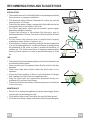
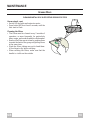
RECOMMENDATIONS AND SUGGESTIONS
INSTALLATION
• The manufacturer will not be held liable for any damages resulting
from incorrect or improper installation.
• The minimum safety distance between the cooker top and the
extractor hood is 650 mm.
• Check that the mains voltage corresponds to that indicated on the
rating plate fixed to the inside of the hood.
• For Class I appliances, check that the domestic power supply
guarantees adequate earthing.
Connect the extractor to the exhaust flue through a pipe of
minimum diameter 120 mm. The route of the flue must be as short
as possible.
• Do not connect the extractor hood to exhaust ducts carrying
combustion fumes (boilers, fireplaces, etc.).
• If the extractor is used in conjunction with non-electrical appliances
(e.g. gas burning appliances), a sufficient degree of aeration must
be guaranteed in the room in order to prevent the backflow of
exhaust gas. The kitchen must have an opening communicating
directly with the open air in order to guarantee the entry of clean
air.
USE
• The extractor hood has been designed exclusively for domestic use
to eliminate kitchen smells.
• Never use the hood for purposes other than for which it has ben
designed.
• Never leave high naked flames under the hood when it is in
operation.
• Adjust the flame intensity to direct it onto the bottom of the pan
only, making sure that it does not engulf the sides.
• Deep fat fryers must be continuously monitored during use:
overheated oil can burst into flames.
• The hood should not be used by children or persons not instructed
in its correct use.
MAINTENANCE
• Switch off or unplug the appliance from the mains supply before
carrying out any maintenance work.
• Clean and/or replace the Filters after the specified time period.
• Clean the hood using a damp cloth and a neutral liquid detergent.
650 mm min.

13GB
2.1
2.2
2
12c
12a
7.2.1 11
11
12a
1
7.3
14.1
15
300
260
898
163
25
520
200
200
670
800 - 1130
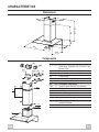
CHARACTERISTICS
Dimensions
Components
Ref. Q.ty Product Components
1 1 Hood Body, complete with: Controls, Light,
Blower, Filters
2 1 Telescopic Chimney comprising:
2.1 1 Upper Section
2.2 1 Lower Section
14.1 2 Air Outlet Connection Extension
15 1 Air Outlet Connection
Ref. Q.ty Installation Components
7.2.1 2 Upper Chimney Section Fixing Brackets
7.3 1 Air Outlet Connection Support
11 6 Wall Plugs
12a 6 Screws 4,2 x 44,4
12c 6 Screws 2,9 x 9,5
Q.ty Documentation
1 Instruction Manual
1 Warranty

14GB
11
12a
395
X
116
1÷2
116
650 min.
7.2.1
INSTALLATION
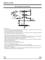
Wall drilling and bracket fixing
Wall marking:
• Draw a vertical line on the supporting wall up to the ceiling, or as high as practical, at the centre
of the area in which the hood will be installed.
• Draw a horizontal line at 650 mm above the hob.
• Place bracket 7.2.1 on the wall as shown about 1-2 mm from the ceiling or upper limit aligning
the centre (notch) with the vertical reference line.
• Mark the wall at the centres of the holes in the bracket.
• Place bracket 7.2.1 on the wall as shown at X mm below the first bracket (X = height of the upper
chimney section supplied), aligning the centre (notch) with the vertical line.
• Mark the wall at the centres of the holes in the bracket.
• Mark a reference point as indicated at 116 mm from the vertical reference line and 395 mm above
the horizontal reference line.
• Repeat this operation on the other side.
• Drill ø 8 mm holes at all the centre points marked.
• Insert the wall plugs 11 in the holes.
• Fix the lower bracket 7.2.1 using the 12a screws (4,2 x 44,4) supplied.
• Fix the upper bracket 7.2.1 and the air outlet connection support 7.3 together using the 2 screws
12a (4,2 x 44,4) supplied.
• Insert the two screws 12a (4,2 x 44,4) supplied in the hood body fixing holes, leaving a gap of 5-
6 mm between the wall and the head of the screw.

15GB
12a
Vr
ø 150
ø 150
14.1
15
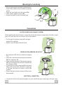
Mounting the hood body
• Before attaching the hood body, tighten the two
screws Vr located on the hood body mounting
points.
• Hook the hood body onto the screws 12a.
• Fully tighten support screws 12a
• Adjust screws Vr to level the hood body.
Connections
DUCTED VERSION AIR EXHAUST SYSTEM
When installing the ducted version, connect the hood to the chimney using either a flexible or rigid
pipe ø 150 mm, the choice of which is left to the installer.
• Fix the pipe in position using sufficient pipe
clamps (not supplied).
• Remove any activated charcoal filters.
RECIRCULATION VERSION AIR OUTLET
• Put connection 15 into the connection support
7.3.
• Insert the connection extension pieces laterally
14.1 in connection 15.
• Make sure that the outlet of the extension pieces
14.1 is horizontally and vertically aligned with
the chimney outlets.
• Connect the air outlet connection 15 to the hood
body outlet using either a flexible or rigid pipe
ø 150 mm, the choice of which is left to the
installer.
• Ensure that the activated charcoal filters have
been inserted.
ELECTRICAL CONNECTION
• Connect the hood to the mains through a two-pole switch having a contact gap of at least 3 mm.

16GB
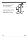
Flue assembly
Upper exhaust flue
• Slightly widen the two sides of the upper flue
and hook them behind the brackets 7.2.1,
making sure that they are well seated.
• Secure the sides to the brackets using the 4
screws 12c (2,9 x 9,5) supplied.
• Make sure that the outlet of the extensions pieces
is aligned with the chimney outlets.
Lower exhaust flue
• Slightly widen the two sides of the flue and hook
them between the upper flue and the wall,
making sure that they are well seated.
• Fix the lower part laterally to the hood body
using the 2 screws 12c (2,9 x 9,5) supplied.
12c
2.1
2.2
2
7.2.1
12c

17GB
USE
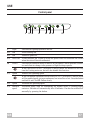
Control panel
L Light Switches the lighting system on and off.
S1 Led Motor running led.
S2 Led Intensive speed led.
S3 Led Filter Alarm indicator led. Lights up when the grease filters are saturated and flashes
when the odour filters are exhausted.
M Motor Switches the extractor motor on and off at low speed. Used to provide a contin-
uos and silent air change in the presence of light cooking vapours.
When the Hood is in ELC (Electronic Comfort) mode, the button will not only
turn the Ducting motor on, but will also disable this function.
V1 Speed Reduces the operating speed.
When the button is pressed with the Motor off, ELC (Electronic Comfort) mode
will be enabled again, giving a continuous, low noise flow of air. Press the button
and hold it until Led S1 flashes slowly.
V2 Speed Increases the operating speed.
V3 Intensive Maximum speed, used for eliminating the highest levels of cooking vapour
speed emission. Switches off automatically after 10 minutes. Can also be switched off
manually by pressing the button.
LM V3S1 S2 S3V2V1

18GB
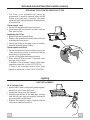
MAINTENANCE
Grease filters
CLEANING METAL SELF-SUPPORTING GREASE FILTERS
Alarm signal reset
• Switch off the lights and extractor motor.
• Press button V2 for at least 3 seconds, until the
leds start to flash.
Cleaning the filters
• The filters must be cleaned every 2 months of
operation, or more frequently for particularly
heavy usage, and can be washed in a dishwasher.
• Remove the filters one at a time by pushing them
towards the back of the group and pulling down
at the same time.
• Wash the filters, taking care not to bend them.
Allow them to dry before refitting.
• When refitting the filters, make sure that the
handle is visible on the outside.

19GB
Lighting
LIGHT REPLACEMENT
20 W halogen light.
• Remove the 2 screws fixing the Lighting support,
and pull it out of from the Hood.
• Extract the lamp from the Support.
• Replace with another of the same type, making
sure that the two pins are properly inserted in
the lamp holder socket holes.
• Replace the Support, fixing it in place with the
two screws removed as above.
Activated charcoal filter (Recirculation version)
REPLACING THE ACTIVATED CHARCOAL FILTER
• The filter is not washable and cannot be
regenerated. It must be replaced when led S3
flashes or at least every 4 months. The alarm
signal will only light up when the extractor motor
is switched on.
Alarm signal reset
• Switch off the lights and extractor motor.
• Press button V2 for at least 3 seconds, until the
leds start to flash.
Replacing the Filter
• Remove the metal grease filters
• Remove the saturated activated carbon filter by
releasing the fixing hooks
• Fit the new filter by hooking it into its seating
• Replace the metal grease filters.
Alarm signal activation
• On the recirulcation version extractor hood, the
filter saturation alarm is activated during
installation or at a later date.
• Switch off the lights and extractor motor.
• Press button V2 for at least 10 seconds, until
the leds start to flash:
2 flashes of the activated carbon odour filter
saturation alarm led = filter ACTIVATED
1 flash of the activated carbon odour filter
saturation alarm led = filter DEACTIVATED.

Quest’apparecchio è conforme alla norma europea sulla bassa tensione C.E.E. 73/23 relativa alla sicurezza elettrica e alle norme
europee: C.E.E. 89/336 relativa alla compatibilità elettromagnetica e C.E.E. 93/68 relativa alla marcatura CE.
This appliance conforms to European Low Voltage Directive 73/23/CEE governing electrical safety, European Directive 89/
336/CEE on Electromagnetic Compatibility and Directive 93/68/CEE regarding CE Marking.
Cet appareil est conforme à la norme européenne en matière de basse tension C.E.E. 73/23 de sécurité électrique ainsi qu’aux
normes européennes : C.E.E. 89/336 en matière de compatibilité électromagnétique et C.E.E. 93/68 en matière de label CE.
Dieses Gerät entspricht folgenden EG-Richtlinien: Niederspannungsrichtlinie EWG 73/23 hinsichtlich elektrischer Sicherheit,
Richtlinie Elektromagnetische Verträglichkeit EWG 89/336 und Richtlinie EWG 93/68 hinsichtlich der CE-Kennzeichnung.
Dit apparaat voldoet aan de Europese laagspanningsnorm 73/23/EEG inzake de elektrische veiligheid en de Europese normen:
89/336/EEG inzake de elektromagnetische compatibiliteit en 93/68/EEG inzake de CE-markering.
436001664 01 - 030117
-
 1
1
-
 2
2
-
 3
3
-
 4
4
-
 5
5
-
 6
6
-
 7
7
-
 8
8
-
 9
9
-
 10
10
-
 11
11


Juno-Electrolux JDK5575E Manuale utente
- Categoria
- Cappe da cucina
- Tipo
- Manuale utente
in altre lingue
- English: Juno-Electrolux JDK5575E User manual