
366811 - 366821
Audio Kit
Manuale installatore • Installation manual
LE06329AB01PC17W05

2

Audio - Kit
3
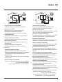
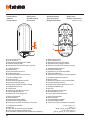
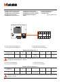
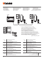
• Vecchio impianto a campanello
Impianto esistente con 3 fili e sola chiamata.
• Old system with bell
Existing system with 3 wires and just call.
• Ancienne installation a sonnette
Installation existante à 3 fils et un seul appel.
• Alte klingelanlage
Vorhandene 3-Leiter Anlage nur mit Ruffunktion.
• Vieja instalación con timbre
Instalación existente con 3 hilos y una llamada.
• Oude deurbelinstallatie
Bestaande 3-aderige installatie met alleen een
oproepfunctie.
• Antiga instalação em campaínha
Instalação existente com 3 fios e somente
chamada.
• Παλαιό σύστηα ε κουδούνι
Παρόν σύστηα ε 3 καλώδια και ια κλήση.
• Система предыдущиx лет выпуска со звонком
3- .
• Eski zil sistemi
3 kablo ve sadece arama ile donatılmış halihazırda
mevcut sistem.
• Stara instalacja z dzwonkiem
Istniejąca instalacja dzwonkowa na 3 przewodach.
•
3
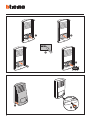
• Nuovo impianto citofonico
Impianto realizzato senza modifiche ai 2 fili
esistenti: chiamata, citofono e serratura.
• New door entry system
System made without modifications to the 2 existing
wires; call, door entry and electric door lock.
• Nouvelle installation phonique
Installation réalisée sans modifications sur les 2 fils
existants: appel, phone, et serrure électrique.
• Neue haustelefonanlage
Anlage ohne Änderungen an den vorhandenen 2 Leiter:
Ruffunktion, haustelefon und elektrischer Schloss.
• Nueva instalación interfónica
Instalación realizada sin las modificaciones a los 2 hilos
existentes: llamada, interfono y cerradura eléctrica.
• Nieuwe deurtelefooninstallatie
Installatie aangelegd zonder wijzigingen aan de 2
bestaande aders: oproep, deurtelefoon en elektrisch
deurslot.
• Nova instalação do intercomunicador
Instalação realizada sem modificar os 2 fios existentes:
chamada, intercomunicador e fechadura eléctrica.
• Νέο σύστηα ενδοεπικοινωνία
Κατασκευή συστήατο χωρί ετατροπέ στα 2
υπάρχοντα καλώδια: κλήση, ενδοεπικοινωνία και κλειδαριά.
• Новая система домофонии
: , .
• Yeni dahili ünite sistemi
Halihazırda mevcut 2 kabloda değişiklik yapılmadan
gerçekleştirilmiş sistem: Arama, dahili ünite ve kilitleme.
• Nowa instalacja domofonowa
Instalacja wykorzystująca 2 istniejące przewody –
wywołanie, domofon, otwarcie drzwi.
•
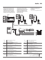
230 Vac 12 V
230 Vac
346040
344242
342911
346040
PRI 110 - 240 V 50 - 60 Hz 370 mA - 225 mA
BUS 26.0 V 600 mA
BUS
PRI
PRI
BUS

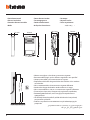
4
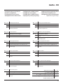
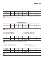
• Altezza consigliata salvo diversa normativa vigente.
• Recommended height, unless different regulations are specified.
• Hauteur conseillée sauf autre norme en vigueur.
• Empfohlene Höhe falls die gesetzlichen Vorschriften nichts anderes
vorschreiben.
• Altura recomendada salvo normativa vigente diferente.
• Aanbevolen hoogte behoudens andere normen in voege.
• Altura aconselhada a não ser se a norma em vigor for diferente.
• Συνιστούενο ύψο πλην διαφορετική ισχύουσα νοοθεσία.
• ,
.
• Yürürlükteki kanunlarca farklı şekilde belirlenenler hariç olarak,
tavsiye edilen yükseklik.
• Zalecana wysokość z zastrzeżeniem innych obowiązujących
przepisów.
160 – 165 cm
135–140 cm
• Dati dimensionali
• Dimensional data
• Données dimensionnelles
• Maße
• Datos dimensionales
• Formaatgegevens
• Dados dimensionais
• εδοένα διαστάσεων
• Размеры
• Boyutsal verler
• Dane wymiarowe
176 mm
31 mm 98 mm
194 mm
78 mm54,5 mm

Audio - Kit
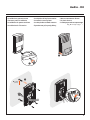
5
1
• Installazione posto esterno
• Entrance panel installation
• Installation du poste extérieur
• Installation der Türstation
• Instalación de la placa exterior
• Installatie externe plaats
• Instalação da unidade externa
• Εγκατάσταση εξωτερική θέση
• Монтаж внешнего блока
• Dış ünte kurma
• Instalacja panelu zewnętrznego
2
S
BU
4
3
Ø 5 mm
(max)

6
1
CLAC
CLAC
2
CLAC
3
4
CLAC
CLAC
5
5
6

Audio - Kit
7
• Installazione del posto interno
• Handset installation
• Installation du poste interne
• Installation der Hausstation
• Instalación de la unidad interior
• Installatie van het intern punt
• Instalação da unidade interna
• Εγκατάσταση τη εσωτερική
θέση
• Монтаж внутреннего блока
• Dahl ünte kurma
• Instalacja miejsca
wewnętrznego
• Attenzione: il citofono deve rispettare le seguenti regole installative:
- deve essere installato solo in ambienti interni
- non deve essere esposto a stillicidio o a spruzzi d’acqua
- non ostruire le aperture di ventilazione
- deve essere usato unicamente all’interno del Kit in cui è venduto
Ogni uso improprio dell’articolo puó comprometterne le caratteristiche di sicurezza.
1
2

8
• Caution: the internal unit must respect the following installation rules:
- it must only be installed indoors
- it must not be exposed to water drops or splashes
- do not block the ventilation openings
- only to be used as part of the kit it is sold with.
An improper use of the item can compromise its safety features.
• Attention: le phone doit respecter les règles d’installation suivantes:
- il doit être monté seulement à l’intérieur
- il ne doit pas être exposé à des suintements ou à des éclaboussures
- ne pas boucher les ouvertures d’aération
- il doit être utilisé uniquement à l’intérieur du kit avec lequel il est vendu.
Tout usage impropre de la référence peut compromettre les caractéristiques de sécurité.
• Achtung: die Hausstation muss unter Beachtung folgender Regeln installiert werden:
- es darf nur im Inneren installiert werden
- es darf nicht Wassertropfen oder-spritzer ausgesetzt werden.
- Belüftungsschlitze nicht verstopfen
- darf nur zusammen mit dem Set verwendet werden, mit dem es verkauft wird
Jeder ungeeigneter Gebrauch des Geräts kann seine Sicherheitseigenschaften beeinträchtigen.
• Atención: el interfono debe respetar las siguientes normas de instalación:
- se debe instalar sólo al cubierto
- no debe estar expuesto a goteo o salpicones de agua
- no tape las aberturas de ventilacióN
- se debe usarse únicamente en el kit con el que se vende.
Cualquier uso impropio del artículo puede comprometer sus características de seguridad.
• Let op: Bij de installatie van de telefoon moet men de volgende voorschriften in acht nemen:
- binnenshuis installeren
- niet aan waterdruppels en -stralen blootstellen
- de ventilatieopeningen niet versperren
- mag uitsluitend in de kit waarmee die verkocht is gebruikt worden
Leder oneigenlijk gebruik kan de veiligheid van het product schaden.
• Atenção: o intercomunicador deve respeitar as seguintes regras para ser instalado:
- deve ser instalado somente internamente
- não deve ser exposto a estilicídio ou borrifos de água
- não deve obstruir as aberturas de ventilação
- deve ser usado exclusivamente no âmbito do kit em que o mesmo é vendido
Qualquer uso impróprio do artigo pode comprometer as suas características de segurança.
• Προσοχή: το σύστηα ενδοεπικοινωνία θα πρέπει να συορφώνεται ε του ακόλουθου
κανόνε εγκατάσταση:
- πρέπει να εγκαθίσταται όνο σε εσωτερικού χώρου - δεν πρέπει να εκτίθεται σε κατακόρυφη ή
υπό γωνία πρόσπτωση νερού
- ην βουλώνετε τα ανοίγατα αερισού
- θα πρέπει να χρησιοποιείται αποκλειστικά στο εσωτερικό του κιτ στο οποίο πωλείται.
Κάθε ακατάλληλη χρήση του είδου πορεί να θέσει σε κίνδυνο τα χαρακτηριστικά ασφαλεία.

Audio - Kit
9
• Внимание:
:
-
-
-
- ,
.
.
• Dkkat: dahl ünte, aşağıdak kurma kurallarına uymalıdır:
- sadece kapalı ortamlara kurulmalıdır
- damlamaya veya su püskürtmelerne maruz bırakılmamalıdır
- havalandırma delklern kapatmayın
- sadece brlkte satıldığı kt çnde kullanılmalıdır
Ürünün her farklı kullanımı emnyet özellklern tehlkeye atablr.
• Uwaga: domofon należy podłączyć według poniższych zasad instalacji:
- instalacja wyłącznie w budynku
- nie może być narażony na wilgoć i zalewanie wodą
- nie zasłaniać otworów wentylacyjnych
- musi być używany wyłącznie z zestawem, w którym został sprzedany.
Nieprawidłowe stosowanie i użycie może ograniczyć bezpieczeństwo produktu.

10
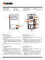
• Posto interno
• Handset
• Poste interne
• Hausstation
• Unidad interior
• Intern punt
• Unidade interna
• Εσωτερική θέση
• Внутренний блок
• Dahl ünte
• Aparat wewnętrzny
3 5
4
2
1
1. Tasto configurabile
2. Tasto serratura
3. Morsetto per collegamento al BUS
4. Sede dei configuratori.
5. Morsetto per pulsante chiamata al piano.
1. Configurable key
2. Door lock key
3. BUS connection terminal
4. Congurator seat.
5. Terminal for floor call pushbutton.
1. Touche configurable
2. Touche serrure
3. Borne de branchement au BUS
4. Logement congurateurs.
5. Borne pour bouton d’appel à l’étage.
1. Konfigurierbare Taste
2. Schlosstaste
3. Klemme für den BUS-Anschluss
4. Sitz der Konguratoren.
5. Klemme für Taste Etagenruf.
1. Tecla programable
2. Tecla cerradura
3. Borne de conexión al BUS
4. Alojamiento configuradores .
5. Borne para pulsador de llamada a la planta.
1. Configureerbare toets
2. Toets slot
3. Klem voor de verbinding met de BUS
4. Plaats van de conguratiemodules.
5. Aansluitklem voor knop voor oproep op verdieping.
1. Botão configurável
2. Tecla da fechadura.
3. Borne para conexão com o BUS
4. Alojamento dos configuradores.
5. Borne para botão de chamada no andar.
1. ιαορφώσιο πλήκτρο
2. Πλήκτρο κλειδαριά
3. Ακροδέκτη για σύνδεση σε BUS
4. Έδρα διαρυθιστών.
5. Ακροδέκτη για πλήκτρο κλήση ορόφου.
1.
2.
3. (BUS)
4. .
5. .
1. Konfgüre edleblr tuş
2. Klt tuşu
3. BUS bağlantısı çn termnal
4. Konfgüratörler yuvası.
5. Katta çağrı butonu termnal.
1. Klawisz programowy
2. Klawisz zamka
3. Zacisk połączenia do BUS
4. Gniazdo konguratoró.
5. Zacisk dla przycisku połączeń na piętrze.
1
2
."BUS"3
4
5

Audio - Kit
11
N = 1-99 Indirizzo posto interno.
P = 0 Accensione luci scale.
1–8 Attivazione Posto Esterno con indirizzo 1-8.
9
Chiamata Posto Esterno con indirizzo 0 - Cen-
tralino di portineria.
N = 1-99 Handset address
P = 0 Switching on staircase lights
1–8 Activation of Entrance Panel with address 1-8
9 0 Entrance Panel – switchboard call
N = 1-99 Adresse poste interne
P = 0 Allumage lumière escaliers
1–8 Activation Poste Externe avec adresse 1-8
9
Appel Poste Externe avec adresse 0 – Standard
de concierge
N = 1-99 Adresse Hausstation
P = 0 Treppenlicht einschalten
1–8 Türstation mit Adresse 1-8 aktivieren
9
Anruf von Türstation mit Adresse o - Hauswart-
zentrale
N = 1-99 Dirección unidad interior
P = 0 Encendido de la luz de la escalera
1–8 Activación de la placa exterior con dirección 1-8
9
Llamada placa exterior con dirección 0 - Centra-
lita de conserjería
N = 1-99 Adres interne post
P = 0 Inschakeling lichten trapzaal
1–8 Activering Externe Post met adres 1-8
9
Oproep Externe Post met adres o – portier-
centrale
N = 1-99 Endereço da unidade interna
P = 0 Ligação das luzes escadas
1–8 Activação da unidade externa com endereço 1-8
9
Chamada da unidade externa com o endereço
0 – Central de portaria
N = 1-99 ιεύθυνση εσωτερική θέση
P = 0 Άναα φώτων σκάλα
1–8
Ενεργοποίηση Εξωτερική Θέση ε διεύθυν-
ση 1-8
9
Κλήση Εξωτερική Θέση ε διεύθυνση 0- Κεντρική
ονάδα θυρωρείου
N = 1-99
P = 0
1–8 1-8
9
0 – -
N = 1-99 İç ünte adres
P = 0 Merdven ışıklarının yakılması
1–8 1-8 adresl Dış Ünte etkn kılınması
9 0 - Kapıcı odası santral adresl Dış Ünte arama
N = 1-99 Adres aparatu wewnętrznego
0 Włączenie światła na klatce schodowej
1–8 Aktywacja Panelu Zew. o adresie 1-8
9
Wywołanie Panelu Zewn. o adresie 0 – Central-
ka portinerii
• Configurazione posto interno
• Handset configuration
• Configuration poste interne
• Konfiguration einer Hausstation
• Configuración unidade interior
• Configuratie intern plaats
• Configuração unidade interna
• ιαόρφωση εσωτερική θέση
• Конфигурация внутреннего блока
• Dâhl ünte konfgürasyonu
• Konfiguracja miejsca wewnętrznego
1-99 = N
0 = P
1–8
0
9

12
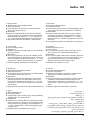
• Posto esterno
• Entrance panel
• Poste extérieur
• Türstation
• Placa exterior
• Externe plaats
• Unidade externa
• Εσωτερικού σηείου
• Внешний блок
• Dış ünte
• Panelu zewnętrznego
OFF ON
7 2
3
4
3
5
6
1
1
3
1. Altoparlante.
2. Sede dei configuratori.
3. Tasti di chiamata.
4. Esclusione tono di chiamata su posto esterno: po-
sizionare lo switch su OFF.
5. Microfono.
6. Morsetti di collegamento BUS e serratura: il mo-
dulo consente di comandare un’elettroserratura
connessa direttamente ai morsetti S+ S- (18 V 4 A
impulsivi - 250 mA di mantenimento su 30 Ohm
max).
7. Regolazione volume microfono e altoparlante.
1. Loudspeaker.
2. Configurator housing.
3. Call keys.
4. To disable the call tone on the entrance panel:
move the switch to the OFF position.
5. Microphone.
6. Terminals for BUS and door lock connection: the
module allows to control an electric door lock
directly connected to the S+ S- terminals (18 V 4 A
impulsive - 250 mA holding current 30 Ohm max).
7. Microphone and loudspeaker volume adjustment.
1. Haut-parleur.
2. Logement des configurateurs.
3. Touches d’appel.
4. Exclusion tonalité d’appel sur poste extérieur: pla-
cer le sélecteur sur OFF.
5. Micro.
6. Bornes de branchement BUS et serrure: le module
permet de commander une serrure électrique
directement branchée aux bornes S+ S- (18V 4A à
impulsions - 250 mA de maintien sur 30 Ohm max.).
7. Réglage du volume haut-parleur et micro.
1. Lautsprecher.
2. Sitz der Konfiguratoren.
3. Ruftasten.
4. Rufton an der Türstation ausschließen: Den Schal-
ter auf OFF schalten.
5. Mikrophon.
6. Anschlussklemmen BUS und Schloss: Das Modul
gestattet es, das Elektroschloss direkt über die
Klemmen S+ S- (18 V 4 A impulsiv - 250 mA Auf-
rechterhalten bei 30 Ohm max) zu steuern.
7. Regelung des Mikrophon- und Lautsprecher-
Lautstärke.

Audio - Kit
13
1. Luidspreker.
2. Plaats configuratoren.
3. Beltoetsen.
4. Beltoon uitsluiten op externe plaats: de schakelaar
op OFF plaatsen.
5. Microfoon.
6. BUS-aansluitklemmen en slot: de module maakt
het mogelijk om een elektroslot aan te sturen dat
direct is aangesloten op de klemmen S+ S- (18 V 4
A impulsen - 250 mA houdstroom max. 30 Ohm).
7. Volumeregeling microfoon en luidspreker.
1. Hoparlör.
2. Konfgüratörler yuvası.
3. Arama tuşları.
4. Dış ünte üzernde arama tonu devreden çıkarıl-
ması: Swtch’ OFF üzernde konumlandırın.
5. Mkrofon.
6. BUS ve klt bağlantı klemensler: Modül, doğrudan
S+ S- klemenslerne (18 V 4 A empülsyonlu - max
30 Ohm üzernde 250 mA muhafaza) bağlı br
elektrkl kld kumanda etmey sağlar.
7. Mkrofon ve hoparlör ses ayarı.
1. Altifalante.
2. Alojamento dos configuradores.
3. Teclas de chamada.
4. Exclusão do tom de chamada na unidade externa:
posicionar o interruptor em OFF.
5. Microfone.
6. Bornes de conexão BUS e fechadura: o módulo
permite comandar uma fechadura eléctrica co-
nectada directamente aos bornes S+ S- (18 V 4 A
impulsivos - 250 mA de mantimento, no máximo
em 30 Ohm).
7. Regulação do volume do microfone e do altifalante.
1. Głośnik.
2. Gniazdo konfiguratorów.
3. Klawisze wywołania.
4. Wyłączenie dźwięku wywołania w aparacie we-
wnętrznym: ustawić przełącznik na OFF.
5. Mikrofon.
6. Zaciski połączenia magistrali BUS i zamka: moduł
umożliwia sterowanie zamkiem elektrycznym
bezpośrednio połączonym z zaciskami S + S – (18
V 4 A impuls - 250 mA utrzymanie przy maks. 30
Ohm)
7. Regulacja głośności mikrofonu i głośnika.
1. Ηχείο
2. Έδρα διαορφωτών.
3. Πλήκτρα κλήση.
4. Αποκλεισό τόνου κλήση στην εξωτερική θέση:
τοποθετήστε το switch στο OFF.
5. Μικρόφωνο
6. Ακροδέκτε σύνδεση BUS και κλειδαριά: η βαθ-
ίδα επιτρεέπι τον έλεγχο ια ηλεκτρική κλειδα-
ριά συνδεδεένη άεσα ε του ακροδέκτε S+
S- (18 V 4 A παλικού - 250 mA διατήρηση στα
30 Ohm max).
7. Ρύθιση όγκου ικροφώνου και ηχείου.
1. Altoparlante
2. Alojamiento de los configuradores
3. Teclas de llamada
4. Exclusión tono de llamada en la placa exterior:
lleve a OFF el interruptor.
5. Micrófono
6. Bornes de conexión BUS y cerradura: el módulo
permite accionar una electrocerradura conectada
directamente a los bornes S+ S- (18 V 4 A impulsi-
vos – 250 mA de mantenimiento en 30 Ohm máx.).
7. Regulación volumen micrófono y altoparlante.
1. .
2. .
3. .
4. : -
OFF ().
5. .
6. :
, -
S+ S- (18 4 A
- 250 30
.).
7. .
1
2
3
4
."OFF"
5
"BUS"6
S
2504
30
7

14
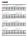
• Congurazione posto esterno
• Entrance panel conguration
• Conguration poste extérieur
• Konguration Türstation
• Conguración placa exterior
• Conguratie externe plaats
• Conguração unidade externa
• ιαρρύθιση εξωτερικού σηείου
• Конфигурация внешнего
блока
• Dış ünite kongürasyonu
• Konguracja panelu
zewnętrznego
·
BUS PL SS
P N T S
T= temporizzatore serratura
S= non deve essere congurato
Numero del configuratore - T
0 = nessun
configuratore
1 2 3 4 5 6 7
4 s 1 s 2 s 3 s
come
pulsante
6 s 8 s 10 s
• P= non deve essere congurato
N= non deve essere congurato
Attenzione: tutte le volte che si modifica la configurazione è necessario togliere e ridare l’alimentazione
all’impianto, attendendo circa 1 minuto.
T= door lock timer relay
S= must not be congured
Number of the configurator - T
0 = no
configurator
1 2 3 4 5 6 7
4 s 1 s 2 s 3 s
as
pushbutton
6 s 8 s 10 s
• P= must not be congured
N= must not be congured
Caution: every time the configuration is altered the system must be switched off and back on again, waiting
for about 1 minute.

Audio - Kit
15
T= temporisateur relais serrure
S= ne doit pas être conguré
Numéro du configurateur - T
0 = aucun
configurateur
1 2 3 4 5 6 7
4 s 1 s 2 s 3 s
comme
poussoir
6 s 8 s 10 s
• P= ne doit pas être conguré
N= ne doit pas être conguré
Attention: chaque fois que l’on modifie la configuration, il faut retirer, puis redonner l’alimentation à
l’installation, après avoir attendu environ 1 minute.
T= zeitgeber schlossrelais
S= muss nicht konguriert werden
Konfiguratornummer - T
0 = kein
Konfigurator
1 2 3 4 5 6 7
4 s 1 s 2 s 3 s
wie
taste
6 s 8 s 10 s
• P= muss nicht konguriert werden
N= muss nicht konguriert werden
Achtung: jedes Mal, wenn die Konfiguration geändert wird, den Strom abschalten, etwa 1 Minute warten
und dann wieder einschalten.
T= temporizador relé cerradura
S= no debe estar congurado
Numero del configurador - T
0 = ningun
configurador
1 2 3 4 5 6 7
4 s 1 s 2 s 3 s
come
pulsador
6 s 8 s 10 s
• P= no debe estar congurado
N= no debe estar congurado
Atención: cada vez que modifica la configuración, es necesario cortar y volver a dar alimentación a la
instalación, después de esperar aproximadamente 1 minuto.
T= timer deurslotrelais
S= moet niet gecongureerd worden
Configurator nummer - T
0 = geen
configurator
1 2 3 4 5 6 7
4 s 1 s 2 s 3 s
als de
drukknop
6 s 8 s 10 s
• P= moet niet gecongureerd worden
N= moet niet gecongureerd worden
Let op: na iedere wijziging in de configuratie moet de installatie ongeveer 1 minuut van het elektriciteitsnet
worden afgesloten.

16
T= temporizador do relé da fechadura
S= não deve ser congurado
Numero do configurador - T
0 = nenhum
configurador
1 2 3 4 5 6 7
4 s 1 s 2 s 3 s
como
botão
6 s 8 s 10 s
• P= não deve ser congurado
N= não deve ser congurado
Atenção: todas as vezes que se modificar a configuração é necessário ligar e desligar a instalação da
energia eléctrica, esperando cerca de 1 minuto.
T= χρονοδιακόπτη κλειδαριά
S=δεν πρέπει να διαρρυθίζεται
Αριθμός του διαρρυθμιστή - T
0 = κανένα διαρ-
ρυθιστή
1 2 3 4 5 6 7
4 s 1 s 2 s 3 s ω κουπί 6 s 8 s 10 s
• P= δεν πρέπει να διαρρυθίζεται
N= δεν πρέπει να διαρρυθίζεται
Προσοχή: κάθε φορά που τροποποιείται η διαρρύθιση χρειάζεται να κόψετε κι επαναφέρετε την τροφοδό-
τηση στην εγκατάσταση, περιένοντα περίπου 1 λεπτό.
T:
S:
Номер конфигуратора - T
0 = -
1 2 3 4 5 6 7
4 c 1 c 2 c 3 c 6 c 8 c 10 c
• P=
N=
Внимание:
, 1 .
T= Klt zaman ayarlayıcı
S= Konfgüre edlmemeldr
Konfigüratör sayısı - T
0 = Konfgüratör
yok
1 2 3 4 5 6 7
4 s 1 s 2 s 3 s Buton olarak 6 s 8 s 10 s
• P= Konfgüre edlmemeldr
N= Konfgüre edlmemeldr
Dkkat: Konfgürasyon her değştrldğnde tess beslemesn kesmek ve yaklaşık 1 dakka bekleyerek yen-
den vermek gerekr.

Audio - Kit
17
T= czas działania przekaźnika zamka
S= nie może być kongurowane
Numer konfiguratora - T
0 = bez
konfiguratora
1 2 3 4 5 6 7
4 s 1 s 2 s 3 s
jak
przycisk
6 s 8 s 10 s
• P= nie może być kongurowane
N= nie może być kongurowane
Uwaga: przy każdej zmianie konfiguracji system musi zostać wyłączony, a po upływie 1 minuty ponow-
nie podłączony do zasilania.
1
7 6 5 4 3 2 1
0
10 8 6 3 2 1 4
T -
P •
N
T
S
1

18
BUS
BUS
PL S+
S-
A
346040
PRI 1 10 - 240 V 50 - 60 Hz 370 mA - 225 mA
BUS 26.0 V 600 mA
BUS
PRI
PRI
BUS
230 Vac
BUS
• Schema base
• Basic diagram
• Schéma de base
• Übersichtszeichnung
• Esquema básico
• Basis schema
• Esquema de base
• Βασικό διάγραμμα
• Базовая схема
• Standart şema
• Schemat podstawowy
•
•
A Pulsante apertura serratura
S+ S- 18 V; 4 A impulsivi
250 mA mantenimento (30 max)
•
A Door lock pushbutton
S+ S- 18 V; 4 A impulsive
250 mA holding current (30 max)
•
A Poussoir d’ouverture serrure
S+ S- 18 V; 4 A impulsifs
250 mA entretien (30 max)
•
A Schalter Türöffner
S+ S- 18 V; 4 A impulsstrom
250 mA Haltestrom (30 max)
•
A Pulsador de apertura de cerradura
S+ S- 18 V; 4 A por impulsos;
250 mA mantenimiento (30 max)
•
A Drukknop opening
S+ S- 18 V; 4 A impulsief;
250 mA onderhoud (30 max)
•
A Botão para abertura do trinco
S+ S 18 V; 4 A instantâneos
250 mA continuos (30 max)
•
A Πλήκτρο ανοίγατο κλειδαριά
S+ S 18 V; 4 A παλικά
250 mA διατήρηση (30 max)
•
A
S+ S 18 - 4A
250 (30 .)
•
A kilit açma butonu
S+ S 18 V; 4 A empülsiyonlu
250 mA muhafaza (30 max)
•
A Przycisk otwarcia zamka drzwi
S+ S 18 V; 4 A impuls
250 mA podtrzymanie (maks. 30 )
A
•
418
30250
S+ S
* • Inserire il configuratore fornito a corredo
• Connect the configurator supplied as standard
•
Mettre en place le configurateur fourni à cet effet
• Den mitgelieferten Konfigurator einsetzen
• Inserte el configurador suministrado
• Breng de standaard geleverde configurator aan
• Inserir o configurador fornecido no equipamento base
• Εισάγετε τον διαορφωτή που χορηγείται στον εξοπλισό
• ,
• Donanım dahlnde tedark edlmş konfgüratörü takın
• Umieścić konfigurator będący na wyposażeniu
P
= –
= –
N
= –
= –
T = –
S = –
N
= –
= –
P
= –
= –
N
= –
= 1 *
P
= –
= –

Audio - Kit
19
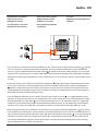
• Schema con serratura a relè
• Diagram with relay door lock
• Schéma avec serrure à relais
• Schema mit Schloss und Relais
• Esquema con cerradura de relé
• Schema met slot met relais
• Esquema do trinco com relè
• Σχέδιο ε κλειδαριά ε ρελέ
• Схема с релейным замком
• Röleli kilitli şema
• Schemat ze zamkiem na
przekaźnik
•
•
A Pulsante apertura serratura
S+ S- 18 V; 4 A impulsivi
250 mA mantenimento (30 max)
•
A Door lock pushbutton
S+ S- 18 V; 4 A impulsive
250 mA holding current (30 max)
•
A Poussoir d’ouverture serrure
S+ S- 18 V; 4 A impulsifs
250 mA entretien (30 max)
•
A Schalter Türöffner
S+ S- 18 V; 4 A impulsstrom
250 mA Haltestrom (30 max)
•
A Pulsador de apertura de cerradura
S+ S- 18 V; 4 A por impulsos;
250 mA mantenimiento (30 max)
•
A Drukknop opening
S+ S- 18 V; 4 A impulsief;
250 mA onderhoud (30 max)
•
A Botão para abertura do trinco
S+ S 18 V; 4 A instantâneos
250 mA continuos (30 max)
•
A Πλήκτρο ανοίγατο κλειδαριά
S+ S 18 V; 4 A παλικά
250 mA διατήρηση (30 max)
•
A
S+ S 18 - 4A
250 (30 .)
•
A kilit açma butonu
S+ S 18 V; 4 A empülsiyonlu
250 mA muhafaza (30 max)
•
A Przycisk otwarcia zamka drzwi
S+ S 18 V; 4 A impuls
250 mA podtrzymanie (maks. 30 )
A
•
418
30250
S+ S
PL S+ S-
BUS
BUS
346040
PRI 1 10 - 240 V 50 - 60 Hz 370 mA - 225 mA
BUS 26.0 V 600 mA
BUS
PRI
PRI
BUS
230 Vac
BUS
8 A cosφ = 1
4 A cosφ = 0,7
3 A cosφ = 0,4
24 Vdc; 24 Vac
24 Vac
24 Vac
NO
NC
C
346250
S-
S+
C
NC
NO
A
P
= –
= –
N
= –
= –
T = –
S = –
N
= –
= 1 *
P
= –
= –
N
= –
= –
P
= –
= –

20
B C
A
D
346040
PRI 110 - 240 V 50 - 60 Hz 370 mA - 225 mA
BUS 26.0 V 600 mA
BUS
PRI
PRI
BUS
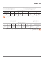
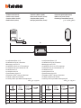
• Installazione no a 3 PI
• Installation of up to 3 handsets
• Montage jusqu’à 3 PI
• Installation von bis zu 3 Türstationen
• Instalación con un máximo de 3 PI
• Installatie tot 3 PI
• Instalação até 3 UI
• Εγκατάσταση έχρι 3 PI
• . 3 .
• En fazla 3 dahili ünite kurma
• Instalacja do 3 aparatów wewnętrznych
.”PI3 •
• Installazione no a 5 PI
• Installation of up to 5 handsets
• Montage jusqu’à 5 PI
• Installation von bis zu 5 Türstationen
• Instalación con un máximo de 5 PI
• Installatie tot 5 PI
• Instalação até 5 UI
• Εγκατάσταση έχρι 5 PI
• . 5 .
• En fazla 5 dahili ünite kurma
• Instalacja do 5 aparatów wewnętrznych
.”PI5 •
0,28 mm
2
BTicino
336904
BTicino
L4669
0,35 mm
2
1 mm
2
A 380 m 610 m 400 m 1000 m
B 200 m 290 m 210 m 580 m
C 180 m 320 m 190 m 560 m
D 30 m 50 m 30 m 100 m
0,28 mm
2
BTicino
336904
BTicino
L4669
0,35 mm
2
1 mm
2
A 340 m 500 m 360 m 1000 m
B 200 m 290 m 210 m 580 m
C 140 m 210 m 150 m 420 m
D 30 m 50 m 30 m 100 m
• Sezione cavi (mm2)
• Cable section (mm2)
• Section câbles (mm2)
• Kabelschnitt (mm2)
• Sección cables (mm2)
• Doorsnede sleutels (mm2)
• Secção cabos (mm2)
• ιατοή καλωδίων (mm2)
• Сечение проводов (мм2)
• Kablo seksiyonu (mm2)
• Przekrój przewodów (mm2)
2 •
La pagina si sta caricando...
La pagina si sta caricando...
La pagina si sta caricando...
La pagina si sta caricando...
-
 1
1
-
 2
2
-
 3
3
-
 4
4
-
 5
5
-
 6
6
-
 7
7
-
 8
8
-
 9
9
-
 10
10
-
 11
11
-
 12
12
-
 13
13
-
 14
14
-
 15
15
-
 16
16
-
 17
17
-
 18
18
-
 19
19
-
 20
20
-
 21
21
-
 22
22
-
 23
23
-
 24
24


Bticino 366811 Istruzioni per l'uso
- Tipo
- Istruzioni per l'uso
- Questo manuale è adatto anche per
in altre lingue
- français: Bticino 366811 Mode d'emploi
- Deutsch: Bticino 366811 Bedienungsanleitung
- português: Bticino 366811 Instruções de operação
Documenti correlati
-
Bticino 364211 Istruzioni per l'uso
-
Legrand 366511 Istruzioni per l'uso
-
-
-
-
-
-
-
-