
2008. 9
303MF56710
Guía de instalación para el IB-40/IB-40
(Type-H) (convertidor Ipv6-Ipv4)
Piezas suministradas
A IB-40........................................................ 1
B Cable ....................................................... 1
C IB-40 (Type-H)......................................... 1
D Cable (Type-H) ........................................ 1
・ Para instalarlo en la ranura HDD del sistema de
impresión del 6030/8030, use el IB-40 (Type-H).
・ Como la inserción incorrecta del IB-40 e IB-40
(Type-H) causa el rompimiento del producto,
instálelos con sumo cuidado.
Precauciones
・ El número de clavijas de conector es diferente
entre IB-40 (A) e IB-40 (Type-H) (C).
IB-40 (A): 60 clavijas; IB-40 (Type-H) (C): 40
clavijas
・ Asegúrese de apagar el MFP y desenchúfelo del
suministro de red eléctrica antes de instalar una
tarjeta de interfaz de red.
・ No toque la superficie de montaje de la PWB con
las manos desnudas, o algo con electricidad
estática.
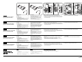
[Cuando instale en 3050/4050/5050/2560/3060]
1. Quite dos tornillos (1) y desmonte la cubierta OPT2.
2. Inserte el IB-40 (A) a lo largo del riel OPT2, de manera que la marca
(2) esté orientada como se ilustra en la figura, y asegúrela con los dos
tornillos (1) que fueron quitados en el paso 1.
3. Conecte el cable (B) a los conectores (3) y (4) de MFP.
4. Conecte el cable de LAN (6) al conector de LAN (5).
Guide d'installation du IB-40/IB-40
(Type-H) (convertisseur IPv6-IPv4)
Pièces fournies
A IB-40........................................................ 1
B Câble ....................................................... 1
C IB-40 (Type-H)......................................... 1
D Câble (Type-H) ........................................ 1
・ Pour l'installation dans le logement du disque dur
du système d'impression du 6030/8030, utiliser le
IB-40 (Type-H).
・ Effectuer l'installation avec le plus grand soin, car si
le IB-40 et le IB-40 (Type-H) sont mal insérés, le
produit risquera de tomber en panne.
Précautions
・ Le IB-40 (A) et le IB-40 (Type-H) (C) possèdent un
nombre de broches de connecteur différent.
IB-40 (A): 60 broches; IB-40 (Type-H) (C): 40
broches
・ Veiller à mettre l'interrupteur principal du MFP hors
tension et à débrancher le MFP de la prise secteur
avant d'installer une carte d'interface de réseau.
・ Ne pas toucher la surface de montage du PWB
avec les mains nues ou avec un objet chargé
d'électricité statique.
[Installation sur les modèles 3050/4050/5050/2560/3060]
1. Retirer les deux vis (1), puis le couvercle OPT2.
2. Insérer le IB-40 (A) le long du rail de l'OPT2 de façon que le repère (2)
soit orienté comme indiqué sur l'illustration, et le fixer à l'aide des deux
vis (1) retirées à l'étape 1.
3. Connecter le câble (B) au connecteur du MFP (3) et au connecteur (4).
4. Connecter le câble LAN (6) au connecteur LAN (5).
Installation Guide for IB-40/IB-40
(Type-H) (IPv6-IPv4 converter)
Supplied parts
A IB-40........................................................ 1
B Cable ....................................................... 1
C IB-40 (Type-H)......................................... 1
D Cable (Type-H) ........................................ 1
・ For installing into the HDD slot of printing system of
6030/8030, use IB-40 (Type-H).
・ Since incorrect insertion of IB-40 and IB-40 (Type-
H) causes breakdown of the product, take care
when installing.
Precautions
・ The number of connector pins is different between
IB-40 (A) and IB-40 (Type-H) (C).
IB-40 (A): 60 pins; IB-40 (Type-H) (C): 40 pins
・ Be sure to turn the MFP switch off and unplug the
MFP from the power supply before installing a
network interface card.
・ Do not touch the PWB mounting surface with bare
hands or something with static electricity.
[When installing in 3050/4050/5050/2560/3060]
1. Remove the two screws (1) and then remove the OPT2 cover.
2. Insert IB-40 (A) along the OPT2 rail so that the marking (2) is oriented
as shown in the figure and secure it with the two screws (1) that have
been removed in step 1.
3. Connect the cable (B) to the MFP connector (3) and the connector (4).
4. Connect the LAN cable (6) to the LAN connector (5).
OPT2
OPT2
4
5
B
6
6
3
4
3
5
2560/3060
3050/4050/5050
B
2560/3060
3050/4050/5050
OPT2
OPT2
1
1
A
A
2
2
A
B
D
C
IB-40 IB-40 (Type-H)
Installationsanleitung für IB-40/IB-40
(Type-H) (IPv6-IPv4-Konverter)
Gelieferte Teile
A IB-40........................................................ 1
B Kabel ....................................................... 1
C IB-40 (Type-H)......................................... 1
D Kabel (Type-H) ........................................ 1
・ Für den Einbau in den HDD-Steckplatz des
Drucksystems 6030/8030 ist IB-40 (Type-H) zu
verwenden.
・ Da falscher Einschub von IB-40 und IB-40 (Type-H)
einen Ausfall des Produkts verursacht, lassen Sie
bei der Installation Sorgfalt walten.
Vorsichtsmaßnahmen
・ Die Zahl der Steckerstifte ist unterschiedlich
zwischen IB-40 (A) und IB-40 (Type-H) (C).
IB-40 (A): 60 Stifte; IB-40 (Type-H) (C): 40 Stifte
・ Schalten Sie den MFP-Schalter aus, und trennen
Sie den MFP von der Stromquelle, bevor Sie eine
Netzwerk-Schnittstellenkarte installieren.
・ Berühren Sie die Platinen-Montagefläche nicht mit
bloßen Händen oder Gegenständen mit statischer
Elektrizität.
[Bei Einbau in 3050/4050/5050/2560/3060]
1. Die zwei Schrauben (1) herausdrehen, und dann die Abdeckung OPT2
entfernen.
2. IB-40 (A) entlang der OPT2-Schiene so einschieben, dass die
Markierung (2) gemäß der Abbildung ausgerichtet ist, und mit den in
Schritt 1 entfernten zwei Schrauben (1) befestigen.
3. Das Kabel (B) an den MFP-Steckverbinder (3) und den Steckverbinder
(4) anschließen.
4. Das LAN-Kabel (6) an den LAN-Anschluss (5) anschließen.
IB-40/IB-40(Type-H)
(IPv6-IPv4 コンバータ)
設置手順書
同梱品
A IB-40 ................................... 1
B ケーブル ................................ 1
C IB-40(Type-H)........................... 1
D ケーブル(Type-H)........................ 1
・6030/8030 のプリンティングシステムの HDD スロッ
トに装着する場合は、IB-40(Type-H)を使用くだ
さい。
・IB-40 と IB-40(Type-H)を挿入し間違えると、製
品の破損になる為、取り付け時注意すること。
注意事項
・IB-40(A)と IB-40(Type-H)(C)では、コネクタ
のピン数が異なります。
IB-40(A):60 ピン /IB-40(Type-H)(C):40 ピン
・ネットワークインタフェースカードを設置する場
合は、MFP 本体の主電源スイッチを OFF にし、電源
プラグを抜いてから作業をおこなう。
・基板の実装面は、素手または静電気を帯びているも
ので触れないこと。
[3050/4050/5050/2560/3060 に設置する場合 ]
1. ビス (1)2 本を外し、OPT2 のカバーを取り外す。
2. IB-40(A) を刻印 (2) が図に示す方向になるように、OPT2 のレールに
沿って挿入し、手順 1 で外したビス (1)2 本で固定する。
English
Français
Español
Deutsch
Italiano
Guida all’installazione di IB-40/IB-40
(Type-H) (convertitore IPv6-IPv4)
Parti di fornitura
A IB-40........................................................ 1
B Cavo ........................................................ 1
C IB-40 (Type-H)......................................... 1
D Cavo (Type-H) ......................................... 1
・ Per l’installazione nell’alloggiamento per HDD di un
sistema di stampa 6030/8030, utilizzare l’IB-40
(Type-H).
・ L’errato inserimento di IB-40 e IB-40 (Type-H)
provoca danni al prodotto. Prestare particolare
attenzione durante l’installazione.
Precauzioni
・ Il numero dei pin di connessione di IB-40 (A) e IB-
40 (Type-H) (C) è diverso.
IB-40 (A): 60 pin; IB-40 (Type-H) (C): 40 pin
・ Assicurarsi di aver spento l’interruttore dell’MFP e
di aver sfilato la spina dell’MFP dalla presa prima di
installare una scheda di interfaccia di rete.
・ Non toccare la superficie di contatto della scheda a
circuito stampato (PWB) con le mani nude od
oggetti che producono elettricità statica.
[Quando si installa nel 3050/4050/5050/2560/3060]
1. Rimuovere le due viti (1), quindi rimuovere il coperchio OPT2.
2. Inserire l’IB-40 (A) lungo la scanalatura OPT2 in modo che le scritte (2)
siano orientate come mostrato nella figura e fissare con le due viti (1)
rimosse nell’operazione 1.
3. Collegare il cavo (B) al connettore MFP (3) e al connettore (4).
4. Collegare il cavo LAN (6) al connettore LAN (5).
3. ケーブル (B) を、MFP コネクタ (3) とコネクタ (4) に接続する。
4. LAN コネクタ (5) に LAN ケーブル (6) を接続する。

2008. 9
303MF56710
11
14
C
12
D
OPT1
HDD
15
9
13
12
15
B
OPT1
HDD
A
11
9
13
14
12
10
B
D
15
OPT1
HDD
7
7
C
A
8
6030/8030
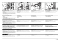
[When installing in 6030/8030]
<For providing both the printer and the scanner with IPv6>
1. Remove the four screws (7) and then remove the OPT1 cover and the
HDD cover.
2. Insert IB-40 (A) along the OPT1 rail so that the marking (8) is oriented
as shown in the figure and secure it with two screws (7) that have been
removed in step 1.
3. Insert IB-40 (Type-H) (C) along the HDD rail so that the marking (8) is
oriented as shown in the figure and secure it with two screws (7) that
have been removed in step 1.
4. Connect the cable (B) to the MFP connector (9) and the scanner
network connector (10).
5. Connect the cable (D) to the MFP connector (11) and the printer
network connector (12).
6. Connect the LAN cable (15) to the LAN connector (13) and the LAN
connector (14).
<For using IB-40 to provide the printer with IPv6>
1. Fit IB-40 (A) to OPT1.
2. Connect the cable (B) to the MFP connector (9) and the printer network
connector (12).
3. Connect the LAN cable (15) to the LAN connector (13).
<For using IB-40 (Type-H) to provide the printer with IPv6>
1. Fit IB-40 (Type-H) (C) to HDD.
2. Connect the cable (D) to the MFP connector (11) and the printer
network connector (12).
3. Connect the LAN cable (15) to the LAN connector (14).
[Installation sur les modèles 6030/8030]
<Pour fournir le IPv6 à l'imprimante et au scanner>
1. Retirer les quatre vis (7) puis retirer le couvercle OPT1 et le couvercle
du disque dur.
2. Insérer le IB-40 (A) le long du rail de l'OPT1 de façon que le repère (8)
soit orienté comme indiqué sur l'illustration, et le fixer à l'aide des deux
vis (7) retirées à l'étape 1.
3. Insérer le IB-40 (Type-H) (C) le long du rail du disque dur de façon que
le repère (8) soit orienté comme indiqué sur l'illustration, et le fixer à
l'aide des deux vis (7) retirées à l'étape 1.
4. Connecter le câble (B) au connecteur du MFP (9) et au connecteur de
réseau du scanner (10).
5. Connecter le câble (D) au connecteur du MFP (11) et au connecteur de
réseau de l'imprimante (12).
6. Connecter le câble LAN (15) au connecteur LAN (13) et au connecteur
LAN (14).
<Utilisation du IB-40 pour fournir l'IPv6 à l'imprimante>
1. Fixer le IB-40 (A) à l'OPT1.
2. Connecter le câble (B) au connecteur du MFP (9) et au connecteur de
réseau de l'imprimante (12).
3. Connecter le câble LAN (15) au connecteur LAN (13).
<Utilisation du IB-40 (Type-H) pour fournir l'IPv6 à l'imprimante>
1. Fixer le IB-40 (Type-H) (C) au disque dur.
2. Connecter le câble (D) au connecteur du MFP (11) et au connecteur de
réseau de l'imprimante (12).
3. Connecter le câble LAN (15) au connecteur LAN (14).
[Cuando instale en 6030/8030]
<Para proveer a la impresora y al escaner con iPv6>
1. Quite cuatro tornillos (7) y luego desmonte la cubierta OPT1 y la
cubierta HDD.
2. Inserte el IB-40 (A) a lo largo del riel OPT1, de manera que la marca
(8) esté orientada como se ilustra en la figura, y asegúrela con los dos
tornillos (7) que fueron quitados en el paso 1.
3. Inserte el IB-40 (Type-H) (C) a lo largo del riel HDD, de manera que la
marca (8) esté orientada como se ilustra en la figura, y asegúrela con
los dos tornillo (7) que fueron quitados en el paso 1.
4. Conecte el cable (B) al conector del MFP (9) y al conector de red del
escaner (10).
5. Conecte el cable (D) al conector del MFP (11) y al conector de red de
la impresora (12).
6. Conecte el cable de LAN (15) a los conectores de LAN (13) y (14).
<Para usar el IB-40 para proveer a la impresora con iPv6>
1. Inserte el IB-40 (A) en OPT1.
2. Conecte el cable (B) al conector del MFP (9) y al conector de red de la
impresora (12).
3. Conecte el cable de LAN (15) al conector de LAN (13).
<Para usar el IB-40 (Type-H) para proveer a la impresora con iPv6>
1. Inserte el IB-40 (Type-H) (C) en HDD.
2. Conecte el cable (D) al conector del MFP (11) y al conector de red de
la impresora (12).
3. Conecte el cable de LAN (15) al conector de LAN (14).
[Bei Einbau in 6030/8030]
<Zur Versorgung von Drucker und Scanner mit IPv6>
1. Die vier Schrauben (7) herausdrehen, und dann die Abdeckung OPT1
und die HDD-Abdeckung entfernen.
2. IB-40 (A) entlang der OPT1-Schiene so einschieben, dass die
Markierung (8) gemäß der Abbildung ausgerichtet ist, und mit den in
Schritt 1 entfernten zwei Schrauben (7) befestigen.
3. IB-40 (Type-H) (C) entlang der HDD-Schiene so einschieben, dass die
Markierung (8) gemäß der Abbildung ausgerichtet ist, und mit den in
Schritt 1 entfernten zwei Schrauben (7) befestigen.
4. Das Kabel (B) an den MFP-Steckverbinder (9) und den Scanner-
Netzwerk-Steckverbinder (10) anschließen.
5. Das Kabel (D) an den MFP-Steckverbinder (11) und den Drucker-
Netzwerk-Steckverbinder (12) anschließen.
6. Das LAN-Kabel (15) an den LAN-Anschluss (13) und den LAN-
Anschluss (14) anschließen.
<Verwendung von IB-40 zur Versorgung des Druckers mit IPv6>
1. IB-40 (A) in OPT1 einsetzen.
2. Das Kabel (B) an den MFP-Steckverbinder (9) und den Drucker-
Netzwerk-Steckverbinder (12) anschließen.
3. Das LAN-Kabel (15) an den LAN-Anschluss (13) anschließen.
<Verwendung von IB-40 (Type-H) zur Versorgung des Druckers mit
IPv6>
1. IB-40 (Type-H) (C) in HDD einsetzen.
2. Das Kabel (D) an den MFP-Steckverbinder (11) und den Drucker-
Netzwerk-Steckverbinder (12) anschließen.
3. Das LAN-Kabel (15) an den LAN-Anschluss (14) anschließen.
[Quando si installa nel 6030/8030]
<Per fornire l’IPv6 sia alla stampante che allo scanner>
1. Rimuovere le quattro viti (7), quindi rimuovere il coperchio OPT1 e
quello HDD.
2. Inserire l’IB-40 (A) lungo la scanalatura OPT1 in modo che le scritte (8)
siano orientate come mostrato nella figura e fissare con le due viti (7)
rimosse nell’operazione 1.
3. Inserire l’IB-40 (Type-H) (C) lungo la scanalatura HDD in modo che le
scritte (8) siano orientate come mostrato nella figura e fissare con le
due viti (7) rimosse nell’operazione 1.
4. Collegare il cavo (B) al connettore MFP (9) e al connettore di rete dello
scanner (10).
5. Collegare il cavo (D) al connettore MFP (11) e al connettore di rete
della stampante (12).
6. Collegare il cavo LAN (15) al connettore LAN (13) e al connettore LAN
(14).
<Per utilizzare l’IB-40 per fornire l’IPv6 alla stampante>
1. Inserire l’IB-40 (A) in OPT1.
2. Collegare il cavo (B) al connettore MFP (9) e al connettore di rete della
stampante (12).
3. Collegare il cavo LAN (15) al connettore LAN (13).
<Per utilizzare l’IB-40 (Type-H) per fornire l’IPv6 alla stampante>
1. Inserire l’IB-40 (Type-H) (C) in HDD.
2. Collegare il cavo (D) al connettore MFP (11) e al connettore di rete
della stampante (12).
3. Collegare il cavo LAN (15) al connettore LAN (14).
4. ケーブル (B) を MFP コネクタ (9) とスキャナネットワークコネクタ
(10) に接続する。
5. ケーブル (D) を MFP コネクタ (11) とプリンタネットワークコネクタ
(12) に接続する。
6. LAN コネクタ (13) と LAN コネクタ (14) に LAN ケーブル (15) を接続す
る。
< IB-40(Type-H)でプリンタを IPv6 対応する場合>
1. IB-40(Type-H)(C) を HDD に取り付ける。
2. ケーブル (D) を MFP コネクタ (11) とプリンタネットワークコネクタ
(12) に接続する。
3. LAN コネクタ (14) に LAN ケーブル (15) を接続する。
< IB-40 でプリンタを IPv6 対応する場合>
1. IB-40(A) を OPT1 に取り付ける。
2. ケーブル (B) を MFP コネクタ (9) とプリンタネットワークコネクタ
(12) に接続する。
3. LAN コネクタ (13) に LAN ケーブル (15) を接続する。
[6030/8030 に設置する場合 ]
<プリンタ・スキャナ両方を IPv6 対応する場合>
1. ビス (7)4 本を外し、OPT1 のカバーと HDD のカバーを取り外す。
2. IB-40(A) を刻印 (8) が図に示す方向になるように、OPT1 のレールに
沿って挿入し、手順 1 で外したビス (7)2 本で固定する。
3. IB-40(Type-H)(C) を刻印 (8) が図に示す方向になるように、HDD の
レールに沿って挿入し、手順 1 で外したビス (7)2 本で固定する。
-
 1
1
-
 2
2


in altre lingue
- English: Copystar CS-3050 Installation guide
- français: Copystar CS-3050 Guide d'installation
- español: Copystar CS-3050 Guía de instalación
- Deutsch: Copystar CS-3050 Installationsanleitung
- 日本語: Copystar CS-3050 インストールガイド
Documenti correlati
Altri documenti
-
KYOCERA KM-3060 Manuale utente
-
KYOCERA KM-2540 Manuale utente
-
KYOCERA TASKALFA 820 Manuale utente
-
HP 9250C DIGITAL SENDER Guida Rapida
-
HP PageWide Managed P77760 Multifunction Printer series Guida utente
-
LevelOne WUS-3200 Manuale utente
-
Dell B2375dfw Mono Multifunction Printer Guida utente
-
-
Philips 346184816 Guida Rapida