Falmec FNLUM36I5SS Guida utente
- Categoria
- Cappe da cucina
- Tipo
- Guida utente
Questo manuale è adatto anche per

EN INSTRUCTIONS BOOKLET
FR MODE D'EMPLOI
ES MANUAL DE INSTRUCCIONES
IT LIBRETTO ISTRUZIONI
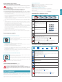
Lumina
Plane
island
FNLUM36I5SS
FNPLS36I5SS

2
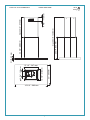
2 1/8” - 55 mm
23 5/8” - 600 mm
ma x 22 5/ 8” - 575 m m
35 3/8” - 900 mm
23” - 585 m m
12 1/ 4” - 310 m m
15 1/ 4” - 387 m m
5 7/8” - 150 mm
25 3/ 4” - 655 m m
ma x 48 3/ 8” - 1230 m m
4 4/8” - 115 m m
99 lb
45 kg
Lumina 36" Cod.: FNLUM36I5SS 120VAC 60Hz 280W

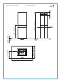
2 6/8” - 70 mm
15 1/4” - 387mm
23 5/8” - 600 mm
12 1/4”
310mm
max 49” - 1244 mm
35 3/8” - 900 mm
21 5/8” - 550 mm
11 7/8” - 301 mm
4 1/2” - 115 mm
92 lb
42 kg
Plane 36" Cod.: FNPLS36I5SS 120VAC 60Hz 280W

4
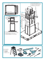
180 mm
7 1/8”
CEILING
FALSE
CEILING
20 5/8” - 523 mm
min. 11” - 280 mm
max. 32 3/4” - 832 mm
Ø150 mm
Ø 5 7/8”
Ø226 mm
Ø 8 7/8”
Ø 9 7/8”
Ø250
mm
13 7/8” - 353 mm
9 5/8” - 245 mm
15” - 382 mm
11 3/4” - 300 mm
Ø 1/4” - 6 mm
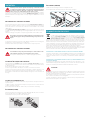
EN - Side outlet which can only be used with false ceiling.
FR - Sortie latérale utilisable uniquement avec faux-plafond.
ES - Salida lateral utilizable solo con falso techo.
IT - Uscita laterale utilizzabile solo con controsotto.
ø5/16"
8 mm
ø1/4"
6 mm
EN- tool required
FR- outil requis
ES- herramienta
requerida
IT - Attrezzi necessari
EN- cable length 5,0ft (1,5m)
FR- longueur de câble 5,0ft (1,5m)
ES- longueur de câble 5,0ft (1,5m)
IT- lunghezza cavo 5,0ft (1,5m)

5
1
2
3
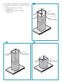
EN - False ceiling (1), ceiling (2) and low ceiling (3) installation.
FR - Installation sur faux-plafond (1), sur plafond (2) et plafond
bas (3).
ES - Instalación en falso techo (1), en techo (2)
y en techo bajo (3).
IT - Installazione su controsotto (1), a sotto (2)
e sotto basso (3).
CEILING
FALSE CEILING
CEILING
CEILING

6
H1
Z
C E IL IN G
Ø 5 7/8” - 150mm
NRS
H = Z + 4 3/4” - 120 mm
NRS
NRS
Z
F
FALSE CEILING
H1
CEILING
H = Z - 4 3/4” - 120 mm
NRS
7 1/8”
180 mm
A
B
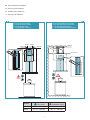
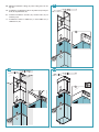
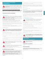
EN INSTALLATION WITH FALSE CEILING
FR INSTALLATION AVEC FAUXPLAFOND
ES INSTALACIÓN CON CIELO RASO
IT INSTALLAZIONE CON CONTROSOFFITTO
EN INSTALLATION ON CEILING
FR INSTALLATION AU PLAFOND
ES INSTALACIÓN EN TECHO
IT INSTALLAZIONE A SOFFITTO
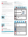
EN - Measurements for installation.
FR - Mesures pour l'installation.
ES - Medidas para la instalacion.
IT - Misure per l’installazione.
Model
Gas (min.) Induction (min.)
Lumina 25 5/8" - 650 mm 20 1/2" - 520 mm
Plane 24 3/4" - 630 mm 20 1/2" - 520 mm

7
1
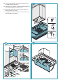
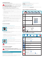
EN - Preliminary operations: remove the panel and the metal lters (1).
FR - Opérations préliminaires:
enlever panneau et ltres métalliques (1).
ES - Operaciones preliminares:
quitar el panel y los ltros metálicos (1).
IT - Operazioni preliminari: togliere pannello e ltri metallici (1).
2
6
5
1
2
3
4

8
2
3
EN - Preliminary operations: disconnect the connector (2), disconnect the Lumina connector (3).
FR - Opérations préliminaires:
débrancher connecteur (2), débrancher connecteur Lumina (3).
ES - Operaciones preliminares:
desconectar el conector (2), desconectar el conector Lumina (3).
IT - Operazioni preliminari: scollegare connettore (2), scollegare connettore Lumina (3).
2
1
2
Lumina NRS
x3
1

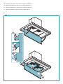
9
4
5
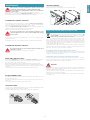
EN - Preliminary operations: motor chamber disassembly
(4), motor chamber bottom trestle assembly (5).
FR - Opérations préliminaires: démontage chambre mo-
teur (4), xation support inférieur sur chambre mo-
teur (5).
ES - Operaciones preliminares: desmontaje de la cámara
del motor (4), montaje de la estructura inferior a la
cámara del motor (5).
IT - Operazioni preliminari: smontaggio camera motore
(4), montaggio traliccio inferiore alla camera motore
(5).
4
1
2
3

10
6
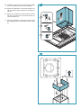
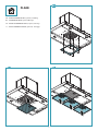
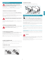
EN - Check valve (6) and NRS pipe (7) installation.
FR - Installation clapet anti-retour (6) et tube NRS (7).
ES - Instalación de la válvula de no retorno (6) y tubo
NRS (7).
IT -
Installazione valvola di non ritorno (6) e tubo NRS (7).
3
4
2
1
NRS
x 3
V 7
7

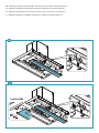
11
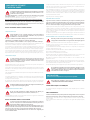
EN -
Ceiling and false ceiling installation. Securing of the upper trestle
to the ceiling (8). Securing of the bottom trestle and the motor
chamber (9).
FR -
Installation sur plafond et faux-plafond. Fixation support
supérieur au plafond (8). Fixation support inférieur et chambre
moteur (9).
ES -
Instalación en techo y falso techo. Fijación estructura superior en
techo (8). Fijación estructura inferior y cámara de motor (9).
IT -
Installazione a sotto e controsotto. Fissaggio traliccio superio-
re a sotto (8). Fissaggio traliccio inferiore e camera motore (9).
CEILING
FALSE CEILING
H1
1
x8
2
1
CEILING
FA
LSE CEILING
Ø 3/8”
Ø8
mm
x4
8
9

12
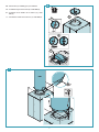
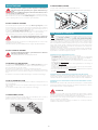
EN - Low ceiling installation. Securing of the bottom trestle and the
motor chamber to the ceiling(14) NRS pipe installation (15).
FR - Installation sur plafonds bas. Fixation support inférieur et
chambre moteur au plafond (14). Installation tube NRS (15).
ES - Instalación del techos bajos. Fijación estructura inferior y cáma-
ra de motor al techo (14). Instalación tubo NRS (15).
IT - Installazione con sotti bassi. Fissaggio traliccio inferiore e ca-
mera motore al sotto (14). Installazione tubo NRS (15).
2
3
V3
x 3
1
14
15

13
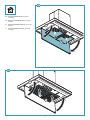
EN - Chimney installation: ceiling (16), false ceiling (17), low ceil-
ing (18).
FR - Installation conduit d’évacuation: sur plafond (16), faux-pla-
fond (17) et plafond bas (18).
ES - Instalación chimenea: en techo (16), en falso techo (17), en
techo bajo (18).
IT - Installazione camino: a sotto (16), a controsotto (17), a
sotto basso (18).
1
2
CEILING
FALSE CEILING
3
1
2
3
CEILING
x4
V5
1
2
3
16
17 18

14
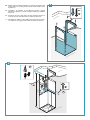
EN - Securing of the shelf (19). Lumina electric connection (20).
Assembly of lters and panel (21).
FR - Fixation panneau inférieur (19). Branchement électrique Lu-
mina (20). Montage ltres et panneau (21).
ES - Fijación del estante (19). Conexión eléctrica Lumina (20).
Montaje de ltros y panel (21).
IT - Fissaggio mensola (19). Collegamento elettrico Lumina (20).
Montaggio ltri e pannello (21).
1
3
V5
5
6
2
4
O N L Y
L U M I N A
1
2
1
2
3
4
19
20 21

15
EN - HP/ACTIVE CARBON FILTERS (optional): assembling
DE - AKTIVKOHLEFILTER/HP (optional): Montage
FR - FILTRES AU CHARBON ACTIF/HP (en option) : Montage
IT - FILTRI AL CARBONE ATTIVO/HP (opzionali) : montaggio
PLANE
22
23 24

16
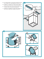
EN - HP/ACTIVE CARBON FILTERS (optional):
assembling
FR - FILTRES AU CHARBON ACTIF/HP (en option) :
Montage
ES - FILTROS DE CARBÓN ACTIVO/HP (opcionales) :
Montaje
IT - FILTRI AL CARBONE ATTIVO/HP (opzionali) :
montaggio
1
2
1
2
25
26

17
ENGLISH
SAFETY INSTRUCTIONS
AND WARNINGS
Installation operations are to be carried out by skilled and qualied in-
stallers in accordance with the instructions in this booklet and in compli-
ance with the regulations in force.
DO NOT use the hood if the power supply cable or other components are damaged:
disconnect the hood from the electrical power supply and contact the Dealer or an author-
ised Servicing Dealer for repairs.
Do not modify the electrical, mechanical or functional structure of the equipment.
Do not personally try to carry out repairs or replacements. Interventions carried out
by incompetent and unauthorised persons can cause serious damage to the unit or
physical and personal harm, not covered by the Manufacturer's warranty.
WARNINGS FOR THE INSTALLER
TECHNICAL SAFETY
Before installing the hood, check the integrity and function of each part.
Should anomalies be noted, do not proceed with installation and contact
the Dealer.
Do NOT install the hood if an aesthetic (or cosmetic) defect has been detected. Put it
back into its original package and contact the dealer.
No claim can be made for aesthetic (or cosmetic) defects once it has been installed.
During installation, always use personal protective equipment (e.g.: Safety shoes) and adopt
prudent and proper conduct.
The installation kit (screws and plugs) supplied with the hood is only to be used on masonry
walls: in case of installation on walls of a dierent material, assess other installation options
keeping in mind the type of wall surface and the weight of the hood (indicated on spec
sheets at the beginning of this manual).
Keep in mind that installations with dierent types of fastening systems from those sup-
plied, or which are not compliant, can cause electrical and mechanical seal danger.
Do not install the hood outdoors and do not expose it to atmospheric elements (rain, wind,
etc.).
ELECTRICAL SAFETY
The electrical system to which the hood is to be connected must be in ac-
cordance with local standards and supplied with earthed connection in
compliance with safety regulations in the country of use. It must also com-
ply with local standards regarding radio antistatic properties.
Before installing the hood, check that the electrical mains power supply corresponds with
what is reported on the identication plate located inside the hood.
The socket used to connect the installed equipment to the electrical power supply must
be within reach: otherwise, install a mains switch to disconnect the hood when required.
Any changes to the electrical system must be carried out by a qualied electrician.
The maximum length of the ue fastening screws (supplied by the manufacturer) must be
13 mm. Use of non-compliant screws with these instructions can lead to danger of an elec-
trical nature.
Do not try to solve the problem yourself in the event of equipment malfunction, but contact
the Dealer or an authorised Servicing Department for repairs.
When installing the hood, disconnect the equipment by removing the
plug or switching o the main switch.
FUMES DISCHARGE SAFETY
Do no connect the equipment to discharge pipes of fumes produced from
combustion (for example boilers, replaces, etc.).
Before installing the hood, ensure that all standards in force regarding discharge of air out of
the room have been complied with.
USER WARNINGS
These warnings have been drawn up for your personal safety and those of
others. You are therefore kindly asked to read the booklet carefully in its
entirety before using the or cleaning the equipment.
The Manufacturer declines all responsibility for any damage caused directly, or in-
directly, to persons, things and pets as a consequence of failing to comply with the
safety warnings indicated in this booklet.
It is imperative that this instructions booklet is kept together with the equipment for
any future consultation.
If the equipment is sold or transferred to another person, make sure that the booklet is
also supplied so that the new user can be made aware of the hood's operation and relative
warnings.
After the stainless steel hood has been installed, it will need to be cleaned to remove any
residues remaining from the protective coating as well as any grease and oil stains which, if
not removed, can cause irreversible damage to the hood surface. To properly clean the unit,
the manufacturer recommends using the supplied moist wipes, which are also available
sold separately.
Insist on original spare parts.
INTENDED USE
The equipment is solely intended to be used to extract fumes generated from cook-
ing food in non-professional domestic kitchens: any other use is improper. Improper
use can cause damage to persons, things, pets and exempts the Manufacturer from
any liability.
The equipment can be used by children over the age of 8 and by persons with reduced
physical, sensory and mental abilities, or with no experience or knowledge, as long as they
do so under supervision or after having received relative instructions regarding safe use of
the equipment and understanding of the dangers connected to it.
Children are not to play with the equipment. Cleaning and maintenance by the user must
not be carried out by children without supervision.
USE AND CLEANING WARNINGS
Before cleaning or carrying out maintenance operations, disconnect the
equipment by removing the plug or switching o the main switch.
Do not use the hood with wet hands or bare feet.
Always check that all electrical parts (lights, extractor fan) are o when the equipment is
not being used.
The maximum overall weight of any objects placed or hung (if applicable) on the hood must
not exceed 3lb 5oz (1.5 Kg).
Always supervise the cooking process during the use of deep-fryers: Overheated oil can
catch re.
Do not leave open, unattended ames under the hood.
Do not prepare food over an open ame under the hood.
Never use the hood without the metal anti-grease lters: in this case, grease and dirt will
deposit in the equipment and compromise its operation.
Accessible parts of the hood can be hot when used at the same time as the cooking ap-
pliances.
Do not carry out any cleaning operations when parts of the hood are still hot.
There can be a risk of re if cleaning is not carried out according to the instructions and
products indicated in this booklet.
Disconnect the main switch when the equipment is not used for long periods of time.
If other appliances that use gas or other fuels are being used at the same
time (boiler, stove, replaces, etc.), make sure the room where the fumes
are discharged is well-ventilated, in compliance with the local regulations.
INSTALLATION
Intended only for qualied personnel
Before installing the hood, carefully read the section 'SAFETY IN-
STRUCTIONS AND WARNINGS'.
TECHNICAL FEATURES
The technical specications are exhibited on the labels located inside the hood.
POSITIONING
The minimum distance between the highest part of the cooking equipment and the
lowest part of the hood is indicated in the installation instructions.
Should the instructions for the gas cooker specify a greater distance, this must be taken
into consideration.
Do not install the hood outdoors and do not expose it to outdoor environment (rain, wind,
etc.).

18
ELECTRICAL CONNECTION
(Intended only for qualied personnel)
Disconnect the equipment from electrical mains power supply before carry-
ing out any operations on the hood.
Ensure that the wires inside the hood are not disconnected or cut:
in the event of damage, contact your nearest Servicing Department.
Refer to qualied personnel for electrical connections.
Connection must be carried out in compliance with the provisions of law in force.
Before connecting the hood to the electrical mains power supply, check that:
• voltage supply corresponds with what is reported on the data plate located inside the
hood;
• the electrical system is compliant and can withstand the load (see the technical speci-
cations located inside the hood);
• the power supply plug and cable do not come into contact with temperatures exceed-
ing 158°F (70 °C);
• the power supply system is eectively and properly connected to earth in compliance
with regulations in force;
•
the socket used to connect the hood is within reach.
In case of:
• devices tted with cables without a plug: the type of plug to use is a ''standardised'' one.
The wires must be connected as follows: yellow-green for grounding, blue for neutral
and brown for the live. The plug must be connected to an adequate safety socket.
•
xed equipment not provided with a power supply cable and plug, or any other device
that ensures disconnection from the electrical mains, with an opening gap of the con-
tacts that enables total disconnection in overvoltage category III conditions.
Said disconnection devices must be provided in the mains power supply in compliance
with installation regulations.
The cable must not be cut o by the switch.
The Manufacturer declines all responsibility for failure to comply with the safety regulations.
FUMES DISCHARGE
EXTERNAL EXHAUST HOOD SUCTION
In this version the fumes and vapours are discharged outside through
the exhaust pipe.
To this end, the hood outlet tting must be connected via a pipe, to an
external output.
The outlet pipe must have:
• a diameter not less than that of the hood tting.
• a slight slope downwards (drop) in the horizontal sections to prevent condensation from
owing back into the motor.
• the minimum required number of bends.
• the minimum required length to avoid vibrations and reduce the suction performance of
the hood.
You are required to insulate the pipes if it passes through cold environments.
In the presence of motors with 800m
3
/h or higher, a check valve is present to prevent
external air owing back.
HOOD WITH INTERNAL RECIRCULATION FILTERING
In this model, the air passes through the charcoal lters to be puried
and recycled in the environment.
Ensure that the active carbon lters are assembled into the hood, if not,
install them as indicated in the assembly instructions.
In this version the check valve must not be assembled: remove it if it is on the air
outlet tting of the motor.
ASSEMBLY INSTRUCTIONS
Intended only for qualied personnel
The hood can be installed in various congurations.
The generic assembly steps apply to all installations; for each case, follow
the specic steps provided for the required installation.
OPERATION
WHEN TO TURN ON THE HOOD?
Switch on the hood at least one minute before starting to cook to direct fumes and vapours
towards the suction surface.
After cooking, leave the hood operating until complete extraction of all vapours and odours.
By means of the Timer function, it is possible to set auto switch-o function which will allow
the hood to turn o automatically after 15 minutes of operation.
WHICH SPEED IS TO BE SELECTED?
1st speed: maintains the circulation of clean air with low electricity consumption.
2nd speed: normal conditions of use.
3rd speed: presence of strong odours and vapours.
4th speed: rapid disposal of odours and vapours.
WHEN SHOULD THE FILTERS BE WASHED OR REPLACED?
The metal lters must be cleaned every 30 hours of operation.
The active carbon lters must be replaced every 3-4 months, depending on the use of the
hood.
For further details refer to the “MAINTENANCE” section.
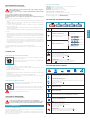
ELECTRONIC PUSHBUTTON PANEL
(PLANE)
Motor ON/OFF
Upon start-up, the speed is that stored at the previous operation.
Increase speed from 1 to 4
Speed 4 is only active for a few min-
utes, then speed 3 activates.
The speeds are indicated by the LEDs
on the keys:
Speed 1
Speed 2
Speed 3
Speed 4
("+" LED ashing)
Reduce speed from 4 to 1
Light on/o
TIMER (red LED ashing)
Auto switch-o after 15 min.
The function deactivates (red LED o) if:
- The TIMER key (
) is pressed again.
- The ON/OFF key (
) is pressed.
FILTER ALARM (red LED steady on with (
) o)
Anti-grease lter maintenance after approximately 30 hours of operation.
Press (
) the meter for 3 seconds to reset.
TOUCH PUSHBUTTON PANEL (LUMINA)
ON/OFF (Blue led steady on)
Motor on/o and Speed 1
ON/OFF (blue led ashing)
If pressed for more than 3 seconds, it activates the 24h cycle (1h ON -> 3h
OFF -> 1h ON)
the function deactivates if:
- The motor turns o (key
)
- After 24h
Speed 2 activation
Speed 3 activation
Speed 4 activation for a few minutes only
Light on/o
TIMER (Red LED ashing)
Auto switch-o after 15 min.
The function deactivates (red LED o) if:
- The motor turns o (key
).
- The speed is changed.
FILTER ALARM (red LED steady on)
Anti-grease lter maintenance after approximately 30 hours of operation.
Press the meter for 3 seconds to reset.

19
ENGLISH
MAINTENANCE
Before cleaning or carrying out maintenance operations, disconnect the
equipment by removing the plug or switching o the main switch.
Do not use detergents containing abrasive, acidic or corrosive substances
or abrasive cloths.
Regular maintenance guarantees proper operation and performance over time.
Special attention is to be paid to the metal anti-grease lters : frequent cleaning of the
lters and their supports ensures that no ammable grease is accumulated.
CLEANING OF EXTERNAL SURFACES
You are advised to clean the external surfaces of the hood at least once every 15 days
to
prevent oily substances and grease from sticking to them. To clean the brushed stainless
steel hood, the Manufacturer recommends using "Magic Steel" wipes.
Alternatively and for all the other types of surfaces, it can be cleaned using a damp cloth,
slightly moistened with mild, liquid detergent or denatured alcohol.
Complete cleaning by rinsing well and drying with soft cloths.
Do not use too much moisture or water around the push button control
panel and lighting devices in order to prevent humidity from reaching
electronic parts.
The glass panels can only be cleaned with specic, non-corrosive or non-abrasive deter-
gents using a soft cloth.
The Manufacturer declines all responsibility for failure to comply with these instructions.
CLEANING OF INTERNAL SURFACES
Do not clean electrical parts, or parts related to the motor inside the hood,
with liquids or solvents.
For the internal metal parts, see the previous paragraph.
METAL ANTI-GREASE FILTERS
It is advised to frequently wash the metal lters (at least once a month) leaving them to
soak in boiling water and cleaning solution for 1 hour, taking care not to bend them.
Do not use corrosive, acid or alkaline detergents.
Rinse them well and wait for them to be completely dry before reassembling them.
Washing in a dishwasher is permitted, however, it may cause the lter material to darken: to
reduce the possibility of this problem from happening, use low-temperature washes (131°F
/ 55°C max.).
To extract and insert the metal anti-grease lters see the assembly instructions.
ACTIVE CARBON FILTERS
These lters retain the odours in the air that passes through them. The puried air is recircu-
lated into the environment.
The active carbon lters must be replaced on average every 3-4 months under normal con-
ditions of use.
See assembly instructions to replace the active carbon lters.
LIGHTING (PLANE)
The range hood is equipped with high eciency, low consumption LED spotlights with an
extremely long life-span under normal use conditions.
Should the LED spotlight need to be replaced, proceed as shown in the gure.
12V
3
1
2
LIGHTING (LUMINA)
The hood has uorescent lamp lighting.
If the lamp ever needs to be replaced, proceed as shown in the gure.
1 2
DISPOSAL AFTER END OF USEFUL LIFE
The crossed-out trash or refuse bin symbol on the appliance means that the
product is WEEE, i.e. “Waste electrical and electronic equipment'', accordingly it
must not be disposed of with regular unsorted waste (i.e. with ''mixed house-
hold waste''), but it must be disposed of separately so that it can undergo specif-
ic processing for its re-use, or a specic treatment, to remove and safely dispose of any
substances that may be harmful to the environment and remove the raw materials that can
be recycled. Proper disposal of these products contributes to saving valuable resources and
avoid potential negative eects on personal health and the environment, which may be
caused by inappropriate disposal of waste.
You are kindly asked to contact your local authorities for further information regarding the
designated waste collection points nearest to you. Penalties for improper disposal of such
waste can be applied in compliance with national regulations.
INFORMATION ON DISPOSAL IN EUROPEAN UNION COUNTRIES
The EU WEEE Directive was implemented dierently in each country, accordingly, if you wish
to dispose of this appliance we suggest contacting your local authorities or dealer to nd
out what the correct method of disposal is.
INFORMATION ON DISPOSAL IN NONEUROPEAN UNION COUNTRIES
The crossed-out trash or refuse bin symbol is only valid in the European Union: if you wish
to dispose of this appliance in other countries, we suggest contacting your local authorities
or dealer to nd out what the correct method of disposal is.
WARNING!
The Manufacturer reserves the right to make changes to the equipment at any time and
without prior notice. Printing, translation and reproduction, even partial, of this manual are
bound by the Manufacturer's authorisation.
Technical information, graphic representations and specications in this manual are for in-
formation purposes and cannot be divulged.
This manual is written in Italian. The Manufacturer is not responsible for any transcription
or translation errors.

20
CONSIGNES DE SÉCURITÉ
ET MISES EN GARDE
Le travail d'installation doit être eectué par des installateurs compétents
et qualiés, conformément aux indications du présent manuel et en res-
pectant les normes en vigueur.
Si le câble d'alimentation ou d’autres composants sont endommagés, la hotte NE
doit PAS être utilisée: débrancher la hotte de l'alimentation électrique et contacter le
revendeur ou un Centre d’Assistance technique agréé pour la réparation.
Ne pas modier la structure électrique, mécanique et fonctionnelle de l'appareil.
Ne pas tenter d'eectuer soi-même des réparations ou des remplacements: les inter-
ventions eectuées par des personnes non compétentes et non qualiées peuvent
provoquer des dommages, éventuellement très graves, à des choses et/ou à des per-
sonnes, non couverts par la garantie du Fabricant.
MISES EN GARDE POUR L’INSTALLATEUR
SÉCURITÉ TECHNIQUE
Avant d'installer la hotte, contrôler l'intégrité et la fonctionnalité de
chaque partie : en cas de constatation d'anomalies, ne pas procéder à
l'installation et contacter le Revendeur.
En cas de constatation d'un défaut esthétique, la hotte NE doit PAS être installée; la
remettre dans son emballage d’origine et contacter le Revendeur.
Après son installation, aucune réclamation ne sera acceptée pour des défauts esthétiques.
Pendant l'installation, toujours utiliser des équipements de protection individuelle (ex.: des
chaussures de sécurité) et adopter un comportement prudent et correct.
Le kit de xation (vis et chevilles) fourni avec la hotte est utilisable uniquement sur des murs en
maçonnerie: s'il faut installer la hotte sur des murs de matériau diérent, évaluer d’autres systèmes
de xation en tenant compte de la résistance du mur et du poids de la hotte (indiqué à la page 2).
Tenir compte du fait que l'installation avec des systèmes de xation diérents de ceux fournis
ou non conformes peut comporter des risques de nature électrique et de tenue mécanique.
Ne pas installer la hotte à l’extérieur et ne pas l’exposer à des agents atmosphériques (pluie, vent, etc.).
SÉCURITÉ ÉLECTRIQUE
Le circuit électrique, auquel est reliée la hotte, doit être aux normes et
muni d’un raccordement à la terre, conformément aux normes de sécurité
du pays d’utilisation; il doit en outre être conforme aux normes euro-
péennes sur l'antiparasite radio.
Avant d'installer la hotte, s'assurer que la tension du secteur correspond à celle reportée sur
la plaque qui se trouve à l'intérieur de la hotte.
La prise utilisée pour le branchement électrique doit être facilement accessible avec l'appa-
reil installé: si cela n'était pas possible, prévoir un interrupteur général pour déconnecter la
hotte en cas de besoin.
Toute modication de l'installation électrique devra être uniquement eectuée par un élec-
tricien qualié.
La longueur maximum de la vis de xation de la cheminée (fournie par le fabricant) est de
13 mm. L'utilisation de vis non conformes avec les présentes instructions peut comporter
des risques de nature électrique.
En cas de dysfonctionnements de l'appareil, ne pas tenter de résoudre personnellement le
problème, mais contacter le revendeur ou un Centre d'Assistance agréé pour la réparation.
Pendant l'installation de la hotte, débrancher l'appareil en retirant la prise
ou en agissant sur l'interrupteur général.
SÉCURITÉ ÉVACUATION DES FUMÉES
Ne pas raccorder l'appareil aux conduits d'évacuation des fumées pro-
duites par la combustion (par ex. chaudières, cheminées, etc.)
Avant l'installation de la hotte, s'assurer que toutes les normes en vigueur sur l’évacuation de
l'air à l'extérieur de la pièce sont respectées.
MISES EN GARDE POUR L'UTILISATEUR
Ces mises en garde ont été rédigées pour votre sécurité et pour celle d'au-
trui, nous vous prions donc de lire attentivement toutes les parties de ce
manuel avant d'utiliser l'appareil ou de le nettoyer.
Le fabricant décline toute responsabilité pour d’éventuels dommages, directs ou in-
directs, pouvant être causés aux personnes, aux choses et aux animaux domestiques,
suite au non-respect des mises en garde de sécurité indiquées dans ce manuel.
Il est très important que ce manuel d'instructions soit conservé avec l'appareil pour
toute consultation future.
Si l'appareil devait être vendu ou transféré à une autre personne, s'assurer que le manuel soit
remis avec celui-ci, de manière à ce que le nouvel utilisateur puisse connaître le fonctionne-
ment de la hotte et des mises en garde relatives.
Après l'installation des hottes en acier inox, il est nécessaire d'eectuer le nettoyage de
celles-ci pour retirer les résidus de colle de la protection et les taches éventuelles de graisse
et d'huile qui, si on ne les enlève pas, peuvent être cause de détérioration irréversible de la
surface de la hotte. Pour cette opération, le fabricant conseille d'utiliser les serviettes four-
nies, disponibles même à l'achat.
Exiger des pièces de rechange originales.
DESTINATION D'UTILISATION
L'appareil est destiné, seulement et exclusivement, pour l'aspiration de fumées générées
par la cuisson d'aliments en milieu domestique, non professionnel: toute autre utilisation
diérente de celle-ci est impropre et peut provoquer des dommages à des personnes,
choses et animaux domestiques, et dégage le Fabricant de toute responsabilité.
L'appareil peut être utilisé par des enfants de plus de 8 ans et des personnes ayant des
capacités physiques, sensorielles ou mentales réduites, ou dépourvues d'expérience ou de
connaissances nécessaires, pourvu qu’ils soient sous surveillance ou bien après qu’ils aient
reçu les instructions relatives à une utilisation sûre de l'appareil et qu’ils aient compris les
dangers correspondants.
Les enfants ne doivent pas jouer avec l'appareil. Le nettoyage et la maintenance destinés à
être eectués par l'utilisateur ne doivent pas être eectués par des enfants sans surveillance.
MISES EN GARDE POUR L'UTILISATION ET LE NETTOYAGE
Avant de procéder à toute opération de nettoyage ou d'entretien, désacti-
ver l'appareil en enlevant la che ou en agissant sur l'interrupteur général.
Ne pas utiliser la hotte avec les mains mouillées ou les pieds nus.
Contrôler toujours que toutes les parties électriques (lumières, aspirateur) soient éteintes
lorsque l'appareil n'est pas utilisé.
Le poids maximum total d'éventuels objets positionnées ou suspendus (où c'est prévu) sur
la hotte ne doit pas dépasser 1,5 kg.
Contrôler les friteuses pendant l'utilisation: l'huile surchauée pourrait s'enammer.
Ne pas allumer de ammes nues sous la hotte.
Ne pas cuisiner avec une amme nue sous la hotte.
Ne jamais utiliser la hotte sans les ltres métalliques anti-graisse ; dans ce cas, la graisse et la
saleté se déposeraient dans l'appareil et compromettrait son fonctionnement.
Des parties accessibles de la hotte peuvent être chaudes si elles sont utilisées avec des
appareils de cuisson.
Ne pas eectuer d’opérations de nettoyage si des parties de la hotte sont encore chaudes.
Si le nettoyage n'est pas mené conformément aux modalités et avec les produits indiqués
dans le présent manuel, un risque d’incendie est possible.
Couper l'interrupteur général si l'appareil n'est pas utilisé pendant de longues périodes.
En cas d'utilisation simultanée avec d'autres éléments (chaudières, poêles,
cheminées, etc.) alimentés au gaz ou avec d'autres combustibles, pourvoir
à une ventilation adéquate du local où s'eectue l'aspiration de la fumée,
conformément aux normes en vigueur.
INSTALLATION
partie réservée uniquement à un personnel qualié
Avant d’eectuer l'installation de la hotte, lire attentivement le chap.
«CONSIGNES DE SÉCURITÉ ET MISES EN GARDE».
CARACTÉRISTIQUES TECHNIQUES
Les données techniques de l'appareil sont reportées sur des étiquettes placées à l'intérieur
de la hotte.
POSITIONNEMENT
La distance minimum entre la partie la plus haute de l'appareil de cuisson et la partie
la plus basse de la hotte de cuisine est indiquée dans les instructions de montage.
Si les instructions de la table de cuisson au gaz spécient une distance supérieure, il faut
en tenir compte.
Ne pas installer la hotte à l’extérieur et ne pas l’exposer à des agents atmosphériques (pluie,
vent, etc.).
La pagina sta caricando ...
La pagina sta caricando ...
La pagina sta caricando ...
La pagina sta caricando ...
La pagina sta caricando ...
La pagina sta caricando ...
La pagina sta caricando ...
La pagina sta caricando ...
La pagina sta caricando ...
La pagina sta caricando ...
La pagina sta caricando ...
La pagina sta caricando ...
-
 1
1
-
 2
2
-
 3
3
-
 4
4
-
 5
5
-
 6
6
-
 7
7
-
 8
8
-
 9
9
-
 10
10
-
 11
11
-
 12
12
-
 13
13
-
 14
14
-
 15
15
-
 16
16
-
 17
17
-
 18
18
-
 19
19
-
 20
20
-
 21
21
-
 22
22
-
 23
23
-
 24
24
-
 25
25
-
 26
26
-
 27
27
-
 28
28
-
 29
29
-
 30
30
-
 31
31
-
 32
32


Falmec FNLUM36I5SS Guida utente
- Categoria
- Cappe da cucina
- Tipo
- Guida utente
- Questo manuale è adatto anche per
in altre lingue
- English: Falmec FNLUM36I5SS User guide
- français: Falmec FNLUM36I5SS Mode d'emploi
- español: Falmec FNLUM36I5SS Guía del usuario
Documenti correlati
-
Falmec FFRIA24W5FS Guida utente
-
-
-
-
Falmec FFPLN48W5FS Guida utente
-
-
-
-
-