
OWNER’S MANUAL
Natural Sound AV Receiver
R-V302K
Thank you for selecting this YAMAHA AV receiver.
R

2
Supplied Accessories ......................................2
Features ..........................................................3
Caution ............................................................4
Profile of This Unit ...........................................5
Speaker Setup ................................................6
Connections ....................................................7
Controls and Their Functions ........................12
Speaker Balance Adjustment ........................17
Basic Operations ...........................................19
Tuning Operations .........................................22
Preset Tuning ................................................23
Using Digital Sound Field Processor (DSP)
.......................................................................26
Enjoying Karaoke...........................................29
Setting the SLEEP Timer ..............................32
Troubleshooting .............................................33
Specifications ................................................34
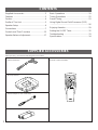
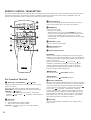
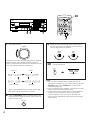
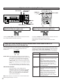
After unpacking, check that the following parts are included.
Indoor FM Antenna
AM Loop Antenna
Antenna adapter (U.S.A. model only)
Batteries (size AA, R6, UM-3)
Remote Control Transmitter
CONTENTS
SUPPLIED ACCESSORIES

3
English
●
5 Speaker Configuration
<
U.S.A. model
>
Main: 60W + 60W (8Ω) RMS Output
Power, 0.04% THD, 20–20,000 Hz
Center: 60W (8Ω) RMS Output
Power,
0.1% THD,
1 kHz
Rear: 20W (8Ω) RMS Output Power,
0.7% THD, 1 kHz
<
Singapore and General models
>
Main: 55W + 55W (8Ω) RMS Output
Power, 0.04% THD, 20–20,000 Hz
Center: 55W (8Ω) RMS Output
Power,
0.1% THD,
1 kHz
Rear: 20W (8Ω) RMS Output Power,
0.7% THD, 1 kHz
● Video Signal Input/Output Capability
● SLEEP Timer
● Remote Control Capability
● 40-Station Random Access Preset Tuning
● Automatic Preset Tuning
● Preset Station Shifting Capability (Preset
Editing)
● IF Count Direct PLL Synthesizer Tuning
System
●
Digital Sound Field Processor
(8 Programs including 4 programs for
Karaoke)
●
Dolby Surround Decoder
( PRO LOGIC, 3 STEREO)
●
Automatic Input Balance Control for
Dolby Surround
●
Test Tone Generator for Easier Speaker
Balance Adjustment
●
Center Channel Output Mode Changing
Capability
●
4 DSP Programs for Karaoke
(BALLAD, POPS, JAZZ, ROCK)
●
ONE TOUCH KARAOKE Button for
Attenuating Vocals from a Music Source
●
VOCAL AID Button to Assist You in
Singing Karaoke
●
2 Microphone Connecting Capability
●
MIC LEVEL and ECHO Level Controls
●
Key Control Capability (in 13 steps)
●
Karaoke Sound Recording Capability
(Recording Your Singing Voice and
Karaoke Effects with the Music Source)
General
Digital Sound Field Processor
Karaoke-functions
Tuner
FEATURES

4
1. To assure the finest performance, please read this manual
carefully. Keep it in a safe place for future reference.
2. Install this unit in a cool, dry, clean place – away from
windows, heat sources, sources of excessive vibration,
dust, moisture and cold. Avoid sources of humming
(transformers, motors). To prevent fire or electrical shock,
do not expose the unit to rain or water.
3. Never open the cabinet. If something drops into the set,
contact your dealer.
4. Do not use force on switches, controls or connection wires.
When moving the unit, first disconnect the power plug and
the wires connected to other equipment. Never pull the
wires themselves.
5. The openings on the cabinet assure proper ventilation of
the unit. If these openings are obstructed, the temperature
inside the cabinet will rise rapidly. Therefore, avoid placing
objects against these openings, and install the unit in well-
ventilated condition. Make sure to allow a space of at least
20 cm behind, 20 cm on the both sides and 30 cm above
the top panel of the unit. Otherwise it may not only damage
the unit, but also cause fire.
6. Always set the VOLUME control to “–
∞
” before starting
the audio source play. Increase the volume gradually to an
appropriate level after playback has been started.
7. Do not attempt to clean the unit with chemical solvents;
this might damage the finish. Use a clean, dry cloth.
8. Be sure to read the “TROUBLESHOOTING” section
regarding common operating errors before concluding that
the unit is faulty.
9. When not planning to use this unit for long periods of time
(ie., vacation, etc.), disconnect the AC power plug from the
wall outlet.
10.To prevent lightning damage, disconnect the AC power
plug and disconnect the antenna cable when there is an
electrical storm.
11.Grounding or polarization – Precautions should be taken
so that the grounding or polarization of an appliance is not
defeated.
12.AC outlet
Do not connect audio equipment to the AC outlet on the
rear panel if that equipment requires more power than the
outlet is rated to provide.
13.Voltage Selector (General Model only)
The voltage selector on the rear panel of this unit must
be set for your local main voltage BEFORE plugging
into the AC main supply.
Voltages are 110/120/220/240 V AC, 50/60 Hz.
This unit is designed for home use only. Do not use this
unit for business purposes.
IMPORTANT
Please record the serial number of this unit in the space
below.
Serial No.:
The serial number is located on the rear of the unit.
Retain this Owner’s Manual in a safe place for future
reference.
WARNING
TO REDUCE THE RISK OF FIRE OR ELECTRIC SHOCK,
DO NOT EXPOSE THIS UNIT TO RAIN OR MOISTURE.
This unit is not disconnected from the AC power source as
long as it is connected to the wall outlet, even if this unit
itself is turned off.
In this state, this unit is designed to consume a very small
quantity of power.
FREQUENCY STEP switch (General Model only)
Because the interstation frequency spacing differs in
different areas, set the FREQUENCY STEP switch (located
at the rear) according to the frequency spacing in your area.
Before setting this switch, disconnect the AC power plug of
this unit from the AC outlet.
WARNING
Do not change the IMPEDANCE SELECTOR switch
setting while the power to this unit is on, otherwise this
unit may be damaged.
IF THIS UNIT FAILS TO TURN ON WHEN THE POWER
SWITCH IS PRESSED
The IMPEDANCE SELECTOR switch may not be set to
either end closely. If so, set the switch to either end closely.
MAINS
I00W MAX. TOTAL
SWITCHED
AC OUTLETS
SINGLE:6ΩMIN. /SPEAKER
:3ΩMIN. /SPEAKER
:6ΩMIN. /SPEAKER
A OR B:4ΩMIN. /SPEAKER
A B:8ΩMIN. /SPEAKER
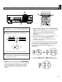
IMPEDANCE SELECTOR
SET BEFORE POWER ON
REAR
REAR
CENTER
MAIN
SINGLE:8ΩMIN. /SPEAKER
:4ΩMIN. /SPEAKER
:8ΩMIN. /SPEAKER
A OR B:8ΩMIN. /SPEAKER
REAR
REAR
CENTER
MAIN
A B:I6ΩMIN ./SPEAKER
VOLTAGE
SELECTOR
IMPEDANCE SELECTOR
(General model)
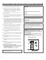
CAUTION : READ THIS BEFORE OPERATING YOUR UNIT.

5
English
PROFILE OF THIS UNIT
You are the proud owner of a Yamaha AV receiver — an extremely sophisticated audio component. The Digital Sound Field
Processor (DSP) built into this unit takes advantage of Yamaha’s undisputed leadership in the field of digital audio processing to
bring you a whole new world of listening experiences. Follow the instructions in this manual carefully when setting up your system,
and this unit will sonically transform your room into a totally new listening environment. In addition, you get incredible realism from
sources encoded with Dolby Surround using the built-in Dolby Pro Logic Surround Decoder.
This unit also has Karaoke functions. They are useful for enjoying Karaoke by using not only multisound sources for Karaoke, but
also normal music sources with vocals. Furthermore, sound-surrounding effects of the DSP expand your Karaoke enjoyment, in
which you will be absorbed in your singing.
Please read this operation manual carefully and store it in a safe place for later reference.
Digital Sound Field Processing (DSP)
What is it that makes live music so good? Today’s advanced
sound reproduction technology lets you get extremely close to
the sound of a live performance, but chances are you’ll still
notice something missing: the acoustic environment of the live
concert hall. Extensive research into the exact nature of the
sonic reflections that create the ambience of a large hall has
made it possible for Yamaha engineers to develop their original
Digital Sound Field Processing Technology to re-create the
acoustic environment of a large concert hall in a home audio
listening room.
Furthermore, our technicians, armed with sophisticated
measuring equipment, have even made it possible to capture
the acoustics of a variety of venues such as an actual concert
hall, live house, etc. to re-create various types of actual live
performance environments for home audio use.
The DSP programs on this unit are made on the basis of this
technology.
Dolby Pro Logic Surround
This unit employs a Dolby Pro Logic Surround decoder similar
to professional Dolby Stereo decoders used in many movie
theaters. By using the Dolby Pro Logic Surround decoder, you
can experience the dramatic realism and impact of Dolby
Surround movie theater sound in your own home. Dolby Pro
Logic employs a four channel five speaker system. The Pro
Logic Surround system divides the input signal into four levels:
the left and right main channels, the center channel (used for
dialog), and the rear surround sound channels (used for sound
effects, background noise, and other ambient noises). The
center channel allows listeners seated in even less-than-ideal
positions to hear the dialog originating from the action on the
screen while experiencing good stereo imaging.
Dolby Surround is encoded on the sound track of pre-recorded
video tapes, laser discs, and some TV/cable broadcasts. When
you play a source encoded with Dolby Surround on this unit,
the Dolby Pro Logic Surround decoder decodes the signal and
distributes the surround-sound effects.
This Dolby Pro Logic Surround Decoder employs a digital
signal processing system. This system improves the stability of
sound at each channel and minimizes crosstalk between
channels, so that positioning of sounds around the room is
more accurate compared with conventional analog signal
processing systems.
In addition, this unit features a built-in automatic input balance
control. This always assures you the best performance without
manual adjustment.
Manufactured under license from Dolby Laboratories Licensing
Corporation. “Dolby”, the double-D symbol and “Pro Logic” are
trademarks of Dolby Laboratories Licensing Corporation.
Enjoying Karaoke with DSP
This unit is a new concept of AV receiver which has Karaoke
functions. They are two microphone input jacks, microphone
level control, echo level control, key level control and two
sound output modes (ONE TOUCH KARAOKE and VOCAL
AID) useful for singing Karaoke by using normal music sources
with vocals.
In addition, the built-in digital sound field processor presents
you with four programs which create sound fields suitable for
singing Karaoke. In those sound fields, you will sing Karaoke
with great feeling and sometimes excitedly.

6
SPEAKER SETUP
SPEAKERS TO BE USED
This unit is designed to provide the best sound-field quality with a 5 speaker configuration. The most effective speakers to use with
this unit are main speakers, rear speakers and a center speaker. You can use one rear speaker only instead of using two rear
speakers, and omit the center speaker. (Refer to the “SPEAKER CONFIGURATION” shown below.)
The main speakers are used for the main source sound plus the effect sounds. They will probably be the speakers from your
present stereo system. The rear speakers are used for the effect and surround sounds, and the center speaker is for the center
sounds (dialog etc.) within programs encoded with Dolby Surround. The center speaker needs to be equal in power to the main
speakers, although the rear speakers should not be equal. However, all the speakers should have high enough power handling to
accept the maximum output of this unit.
SPEAKER CONFIGURATION
5-Speaker Configuration
This configuration is the most effective and recommended one.
In this configuration, the center speaker is necessary as well as
the rear speakers. If the program DOLBY PRO LOGIC or
DOLBY 3 STEREO is selected, conversations will be output
from the center speaker and the ambience will be excellent.
• Set the center channel mode to the “NORMAL” or “WIDE”
position. (For details, refer to page17.)
4-Speaker Configuration (without the center speaker)
The center speaker is not used in this configuration. If the
program DOLBY PRO LOGIC is selected, the center sound is
output from the left and the right main speakers. The program
DOLBY 3 STEREO is useless in this configuration. However,
the sound effect of other programs can be almost the same as
that of the 5-speaker configuration.
• Be sure to set the center channel mode to the “PHANTOM”
position. (For details, refer to page 17.)
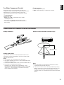
SPEAKER PLACEMENT
The recommended speaker configuration, the 5-speaker
configuration, will require two speaker pairs: main speakers
(your normal stereo speakers), and rear speakers, plus a
center speaker. When you place these speakers, refer to the
following.
Main: In normal position. (The position of your present
stereo speaker system.)
Rear: Behind your listening position, facing slightly inward.
Nearly 1.8 m (approx. six feet) up from the floor.
Center: Precisely between the main speakers. (To avoid
interference with TV sets, use a magnetically shielded
speaker.)
Front R
Center
Front L
TV set
Rear R
Rear L
Main L Center Center
Main R
Rear L
Rear R
Main L
Main R
Rear L
Rear R
Main L
Main R
Rear
Main L
Main R
Rear
Main L
Main R
Note
As this unit is equipped with a monaural amplifier for the rear channel, sounds output from the rear speakers are in monaural. So,
you may use one rear speaker only instead of using two rear speakers. However, the use of two rear speakers is recommended
when there are more than one listener in the listening room.
When using one rear speaker, place it right behind your listening position.
(Two rear speakers)
(One rear speaker)
(Two rear speakers)
(One rear speaker)

7
English
CONNECTIONS
Never plug in this unit and other components until all connections are completed.
CONNECTIONS WITH OTHER COMPONENTS
When making connections between this unit and other components, be sure all connections are made correctly, that is to say L (left)
to L, R (right) to R, “+” to “+” and “–” to “–”. Also, refer to the owner’s manual for each component to be connected to this unit.
* If you have YAMAHA components numbered as 1, 2, 3, etc. on the rear panel, connections can be made easily by making sure
to connect the output (or input) terminals of each component to the same-numbered terminals of this unit.
*
1
,
*
2
: See page 10.
FM
ANT
AM
ANT
GND
75Ω
UNBAL.
GND
MONITOR OUT
VIDEO
IN OUTVCR
VIDEO SIGNAL
CD
TAPE
( MD )
VIDEOPHONO VCR
TAPE
PB
REC
OUT
IN OUT
AUDIO SIGNAL
3 4
1
MAINS
SINGLE:6ΩMIN. /SPEAKER
:3ΩMIN. /SPEAKER
:6ΩMIN. /SPEAKER
A OR B:4ΩMIN. /SPEAKER
A B:8ΩMIN. /SPEAKER
IMPEDANCE SELECTOR
SET BEFORE POWER ON
REAR
REAR
CENTER
MAIN
SINGLE:8ΩMIN. /SPEAKER
:4ΩMIN. /SPEAKER
:8ΩMIN. /SPEAKER
A OR B:8ΩMIN. /SPEAKER
REAR
REAR
CENTER
MAIN
A B:I6ΩMIN ./SPEAKER
50 kHz
/9 kHz
I00 kHz
/I0 kHz
FREQUENCY
STEP
FM
/AM
VOLTAGE
SELECTOR
I00W MAX. TOTAL
SWITCHED
AC OUTLETS
VIDEO IN
GND
OUTPUT
LINE OUT
LINE IN
OUTPUT
VIDEO OUT
AUDIO OUT
AUDIO IN
VIDEO IN
AUDIO OUT
VIDEO OUT
(General model)
To AC outlet
Turntable
LD player etc.
Video cassette recorder
Tape deck,
MD recorder, etc.
CD player
Monitor TV
*
2
*
1

8
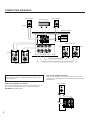
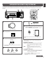
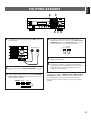
CONNECTING SPEAKERS
REAR REARCENTER
CAUTION
SEE INSTRUCTION MANUAL FOR CORRECT SETTING.
MAIN
SPEAKERS
A
B
REAR
SINGLE
SINGLE:6ΩMIN. /SPEAKER
:3ΩMIN. /SPEAKER
:6ΩMIN. /SPEAKER
A OR B:4ΩMIN. /SPEAKER
A B:8ΩMIN. /SPEAKER
IMPEDANCE SELECTOR
SET BEFORE POWER ON
REAR
REAR
CENTER
MAIN
SINGLE:8ΩMIN. /SPEAKER
:4ΩMIN. /SPEAKER
:8ΩMIN. /SPEAKER
A OR B:8ΩMIN. /SPEAKER
REAR
REAR
CENTER
MAIN
A B:I6ΩMIN ./SPEAKER
Rear speaker Rear speaker
Center speaker
Main speakers B
Left
Right
Left
Right
Main speakers A
Left
Right
Note
Use speakers with the specified impedance shown on the
rear of this unit.
Note on main speaker connections:
One or two speaker systems can be connected to this unit. If
you use only one speaker system, connect it to either the
SPEAKERS A or B terminals.
Note on rear speaker connection:
Only one rear speaker can also be used in place of two rear
speakers. For connecting one rear speaker, follow the method
shown below.
REAR REARCENTER
REAR
SINGLE
Rear speaker
(General model)

9
English
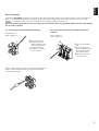
For connecting to the MAIN SPEAKERS terminals
Red: positive (+)
Black: negative (–)
➀
Unscrew the knob.
➁
Insert the bare wire.
[Remove approx. 5mm
(1/4”) insulation from
the speaker wires.]
➂
Tighten the knob and
secure the wire.
Banana Plug connections are also possible (except Singapore
model). Simply insert the Banana Plug connector into the
corresponding terminal.
For connecting to the REAR and CENTER SPEAKERS
terminals
Red: positive (+)
Black: negative (–)
➀
Press up and hold the
tab.
➁
Insert the bare wire.
[Remove approx. 5mm
(1/4”) insulation from
the speaker wires.]
➂
Release the tab and
secure the wire.
➁
➂
➀
1
2
3
How to Connect:
Connect the SPEAKERS terminals to your speakers with wire of the proper gauge, cut as short as possible. If the connections are
faulty, no sound will be heard from the speakers. Make sure that the polarity of the speaker wires is correct, that is the + and –
markings are observed. If these wires are reversed, the sound will be unnatural and lack bass.
Caution
Do not let the bare speaker wires touch each other and do not let them touch any metal part of this unit. This could damage
this unit and/or speakers.

10
Be sure to switch this only when the power of this unit is turned
off.
Select the position whose requirements your speaker system
meets.
WARNING
Do not change the IMPEDANCE SELECTOR switch
setting while the power to this unit is on, otherwise this
unit may be damaged.
IF THIS UNIT FAILS TO TURN ON WHEN THE POWER
SWITCH IS PRESSED
The IMPEDANCE SELECTOR switch may not be set to
either end closely. If so, set the switch to either end closely.
(Upper position)
Rear: If you use one rear speaker, the impedance of the
speaker must be 6Ω or higher.
If you use two rear speakers, the impedance of each
speaker must be 3Ω or higher.
Center: The impedance of the center speaker must be 6Ω or
higher.
Main: If you use one pair of main speakers, the impedance
of each speaker must be 4Ω or higher.
If you use two pairs of main speakers, the impedance
of each speaker must be 8Ω or higher.
(Lower position)
Rear: If you use one rear speaker, the impedance of the
speaker must be 8Ω or higher.
If you use two rear speakers, the impedance of each
speaker must be 4Ω or higher.
Center: The impedance of the center speaker must be 8Ω or
higher.
Main: If you use one pair of main speakers, the impedance
of each speaker must be 8Ω or higher.
If you use two pairs of main speakers, the impedance
of each speaker must be 16Ω or higher.
IMPEDANCE SELECTOR switch
MAINS
I00W MAX. TOTAL
SWITCHED
AC OUTLETS
SINGLE:6ΩMIN. /SPEAKER
:3ΩMIN. /SPEAKER
:6ΩMIN. /SPEAKER
A OR B:4ΩMIN. /SPEAKER
A B:8ΩMIN. /SPEAKER
IMPEDANCE SELECTOR
SET BEFORE POWER ON
REAR
REAR
CENTER
MAIN
SINGLE:8ΩMIN. /SPEAKER
:4ΩMIN. /SPEAKER
:8ΩMIN. /SPEAKER
A OR B:8ΩMIN. /SPEAKER
REAR
REAR
CENTER
MAIN
A B:I6ΩMIN ./SPEAKER
VOLTAGE
SELECTOR
(General model)
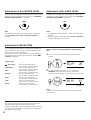
ABOUT THE ACCESSORY TERMINALS
2 AC OUTLETS (SWITCHED)
Use these to connect the power cords from your components
to this unit.
The power to the SWITCHED outlets is controlled by this unit’s
POWER switch or the provided remote control transmitter’s
POWER key. These outlets will supply power to any
component whenever this unit is turned on.
The maximum power (total power consumption of components)
that can be connected to the SWITCHED AC OUTLETS is 100
watts.
GND terminal (For turntable use)
Connecting the ground wire of the turntable to the GND
terminal will normally minimize hum, but in some cases better
results may be obtained with the ground wire disconnected.
*
1
*
2

11
English
ANTENNA CONNECTIONS
●
Each antenna should be connected to the designated terminals correctly, referring to the following diagram.
●
Both AM and FM indoor antennas are included with this unit. In general, these antennas will probably provide sufficient signal
strength. Nevertheless, a properly installed outdoor antenna will give clearer reception than an indoor one. If you experience
poor reception quality, an outdoor antenna may result in improvement.
Connecting the AM loop antenna
* The AM loop antenna should be placed apart from the main unit. The antenna may be hung on a wall.
* The AM loop antenna should be kept connected, even if an outdoor AM antenna is connected to this unit.
GND terminal
For maximum safety and minimum interference, connect the
GND terminal to a good earth ground. A good earth ground is
a metal stake driven into moist earth.
Notes
●
When connecting the indoor
FM antenna, insert its
connector into the FM ANT
terminal firmly.
●
If you need an outdoor
FM antenna to improve
FM reception quality, either
300-ohm feeder or coaxial cable may be used. In locations
troubled by electrical interference, coaxial cable is
preferable.
FM
ANT
AM
ANT
GND
75Ω
UNBAL.
GND
50kHz
/9kHz
I00kHz
/I0kHz
FREQUENCY
STEP
FM
/AM
➀
➁
➂
Orient so that the best
reception is obtained.
1 2 3
Outdoor FM antenna
Outdoor AM antenna
(General model)
AM loop
antenna
(included)
Ground
75-ohm/300-ohm
antenna adapter
75-ohm/300-ohm
antenna adapter
75-ohm coaxial cable
300-ohm feeder
Indoor FM
antenna
(included)

12
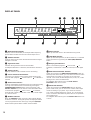
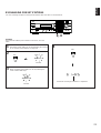
CONTROLS AND THEIR FUNCTIONS
FRONT PANEL
POWER
SPEAKERSPHONES
A
ON
B
OFF
BASS TREBLE BALANCE
VOLUME
55
4
3
2
l
0
l
2
3
4
55
4
3
2
l
0
l
2
3
4
LR
l6
20
28
40
60
l2
8
4
2
0
–dB
55
4
3
2
l
0
l
2
3
4
FM
/
AM
MAN'L
/
AUTO FM
TUNING
MODE
AUTO
/
MAN’L MONO
ONE TOUCH
KARAOKE
DOWN
TUNING
UP VOCAL AID
MEMORY
EDIT
KEY CONTROL
A
/
B
/
C
/
D
/
E
1
2 3 4 5 6 7 8
TAPE (MD)
MONITOR
VIDEOVCR
TUNER
CD
PHONO
ECHO
LEVEL
MIC 2MIC 1
MIN MAX
REAR
LEVEL
CENTER
LEVEL
0l0 0l0
PRO LOGIC 3 STEREO
SUR/KARAOKE
EFFECT
BALLAD
POPS
JAZZ
LIVE HOUSE
CENTER
MODEHALL
ROCK
KARAOKE
MIN MAX
123 4 5 06A
BC D E F RGH IKLNP TSQ
J
OM
7
8
9
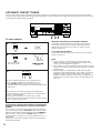
1 POWER switch
Press this switch to switch the power on. Press it again to
switch the power off.
2 Standby mode indicator (Except U.S.A. model)
While the power is on, pressing the POWER key on the remote
control transmitter switches the unit to the standby mode. In
this mode, this indicator is illuminated.
3 Remote control sensor
Receives signals from the remote control transmitter.
4 Display panel
Shows various information. (Refer to page 16 for details.)
5 Input selector buttons
Select a program source to listen to or watch. When a button is
pressed, the name of selected source appears on the display.
6 DSP program selector buttons ( PRO LOGIC,
3 STEREO, LIVE HOUSE, HALL)
Select a DSP program. When a button is pressed, the name of
selected program lights up on the display.
7 SUR/KARAOKE EFFECT button
When the built-in digital sound field processor (DSP) (including
the Dolby Pro Logic Surround decoder) is on, pressing this
button cancel it and turns this unit into the normal 2-channel
stereo mode.
Pressing this button once more turns the DSP on and restores
the program which was selected the last time.
* If this button is pressed when a normal DSP program (
PRO LOGIC, 3 STEREO, LIVE HOUSE or HALL) is
selected, “EFFECT OFF” lights up on the display, however,
if pressed when a DSP program for Karaoke (BALLAD,
POPS, JAZZ or ROCK) is selected, “E. OFF” appears on
the display.
8 CENTER MODE button
Selects a center channel output mode (NORMAL, WIDE or
PHANTOM). Changing the center channel output mode is
effective only when the program, PRO LOGIC or 3
STEREO is selected. (For details, refer to page 17.)
* When the DOLBY 3 STEREO program is used, the
“PHANTOM” mode cannot be selected.
9 DSP program selector buttons for Karaoke (BALLAD,
POPS, JAZZ, ROCK)
Select a DSP program. When a button is pressed, the name of
selected program appears on the display.
0 KARAOKE button
Pressing this button switches this unit from the state in which a
normal DSP program ( PRO LOGIC, 3 STEREO, LIVE
HOUSE or HALL) is selected to the state in which a DSP
program for Karaoke (BALLAD, POPS, JAZZ or ROCK) is
selected, and vice versa. If switched, the program which was
used the last time in each state is recalled.
Pressing this button also switches the function of the
SUR/KARAOKE EFFECT button from turning on/off a normal
DSP program to turning on/off a program for Karaoke, and vice
versa.
A VOLUME control
Used to raise or lower the volume level.

13
English
B PHONES jack
When you listen with headphones,
connect the headphones to the
PHONES jack. You can listen to
the sound to be output from the
main speakers through headphones.
When listening with headphones
privately, set both the SPEAKERS A
and B switches to the OFF position
and switch off the digital sound field processor by pressing the
SUR/KARAOKE EFFECT button on the front panel or the
EFFECT ON/OFF key on the remote control transmitter.
C SPEAKERS switches
Set the switch A or B (or both A and B) for the main speaker system
(connected to this unit) you will use to the ON position. Set the switch
for the main speaker system you will not use to the OFF position.
D A/B/C/D/E button
Press this button to select a desired group (A–E) of preset stations.
E Preset station number selector buttons
Select a preset station number (1 to 8).
F Tone controls
These controls are effective only for the sound from the main
speakers.
BASS
Used to increase or decrease the low frequency response.
The 0 position produces flat response.
TREBLE
Used to increase or decrease the high frequency response.
The 0 position produces flat response.
G BALANCE control
Adjusts the balance of the output volume to the left and right
speakers to compensate for sound imbalance caused by
speaker location or listening room conditions.
H CENTER LEVEL control
Adjusts the sound output level of the center speaker.
I REAR LEVEL control
\Adjusts the sound output level of the rear speakers.
J FM/AM button
Press this button to switch the reception band to FM or AM.
K MEMORY (MAN’L/AUTO FM) button
When this button is pressed, the MEMORY indicator flashes for
about 5 seconds. During this period, select a desired preset
station number by pressing the corresponding preset station
number selector button to enter the displayed station into the
memory.
When this button is pressed and held for about 3 seconds, the
automatic preset tuning begins. (Refer to page 24 for details.)
L EDIT button
This button is used to exchange the places of two preset
stations with each other.
M TUNING DOWN/UP button
Used for tuning. Press the “UP” side to tune in to higher
frequencies, and press the “DOWN” side to tune in to lower
frequencies.
N TUNING MODE (AUTO/MAN’L MONO) button
Press this button to switch the tuning mode to automatic or
manual. To select the automatic tuning mode, press this button
so that “AUTO” lights up on the display. To select the manual
tuning mode, press this button so that “AUTO” goes off.
O VOCAL AID button
This button functions only when a DSP program for Karaoke,
BALLAD, POPS, JAZZ or ROCK is selected, or the DSP is
turned off (so that “E. OFF” appears on the display).
Pressing this button so that “VOCAL AID” lights up on the
display turns this function on, and whenever this button is
pressed, one of three audio output modes is selected in turn.
When the “VOCAL CUT” mode is selected, while playing a
source, medium frequencies (vocals, etc.) of the source sound
are attenuated only when there is an input from the
microphone.
To cancel this function, press this button once or more until
“VOCAL AID” goes off from the display.
This button is useful for singing Karaoke using a normal audio
source with vocals or a multisound source for Karaoke use.
P KEY CONTROL button
This button functions only when a DSP program for Karaoke,
BALLAD, POPS, JAZZ or ROCK is selected, or the DSP is off.
Pressing this button changes key of the tune currently playing.
The current key level is shown on the display.
(Left side): Whenever this side is pressed, key of the
track becomes lower.
(Right side): Whenever this side is pressed, key of the
track becomes higher.
Q ONE TOUCH KARAOKE button
This button functions only when a DSP program for Karaoke,
BALLAD, POPS, JAZZ or ROCK is selected, or the DSP is
turned off (so that “E. OFF” appears on the display).
Pressing this button so that “ONE TOUCH KARAOKE” lights
up on the display turns this function on, and whenever this
button is pressed, one of three audio output modes is selected
in turn. When the “VOCAL CUT” mode is selected, medium
frequencies (vocals, etc.) of the playing source sound are
attenuated.
To cancel this function, press this button once or more until
“ONE TOUCH KARAOKE” goes off from the display.
This button is useful for singing Karaoke using a normal audio
source with vocals or a multisound source for Karaoke use.
R MIC jacks
One or two microphones can be connected to these jacks.
These are available when a DSP program for Karaoke,
BALLAD, POPS, JAZZ or ROCK is selected, or the DSP is off.
S MIC LEVEL control
This control functions only when a DSP program for Karaoke,
BALLAD, POPS, JAZZ or ROCK is selected, or the DSP is off.
This control adjusts the level of sound signals input from the
microphone(s) connected to this unit’s MIC jacks.
T ECHO level control
This control functions only when a DSP program for Karaoke,
BALLAD, POPS, JAZZ or ROCK is selected, or the DSP is off.
This control adjusts the level of echo applied to sound signals
input from the microphone(s) connected to this unit’s MIC jacks.
PHONES

For Control of This Unit
1 DELAY/KEY and TIME/KEY – ( )/+ ( ) keys
Adjust the delay time (DELAY) and key level of the currently
playing tune (KEY).
Select the item which you want to adjust by pressing the
DELAY/KEY key and adjust its time or level by pressing the
TIME/KEY – ( )/+ ( ) key.
* The key level cannot be changed when a normal DSP
program ( PRO LOGIC, 3 STEREO, LIVE HOUSE or
HALL) is selected.
2 Tuner keys
Controls tuner.
+: Selects higher preset station number.
–: Selects lower preset station number.
A/B/C/D/E: Selects the group (A – E) of preset station
numbers.
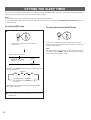
3 SLEEP timer key
This key is used to turn the built-in SLEEP timer on and off,
and to set the SLEEP time. (See page 32 for details.)
4 POWER key
Turns the power on/off.
* (Except U.S.A. model)
While the power is on, pressing the POWER key on the
remote control transmitter switches the unit from the power-
on mode to the standby mode, and vice versa. (In the
standby mode, the standby mode indicator on the front panel
is illuminated.)
5 VOLUME +/– keys
Turns the volume level up/down.
6 Input selector keys
Selects input source.
7 Program selector keys
PROGRAM:
When the built-in digital sound field processor (including the
Dolby Pro Logic Surround decoder) is on, this key changes the
currently selected DSP program whenever the right or left side
of this key is pressed.
When a normal DSP program ( PRO LOGIC, 3
STEREO, LIVE HOUSE or HALL) is selected, a program
change is made among them. When a DSP program for
Karaoke (BALLAD, POPS, JAZZ or ROCK ) is selected, a
program change is made among them.
PROLOGIC:
Directly selects the PRO LOGIC program.
3 STEREO:
Directly selects the 3 STEREO program.
8 EFFECT ON/OFF key
When the built-in digital sound field processor (DSP) (including
the Dolby Pro Logic Surround decoder) is on, pressing this key
cancel it and turns this unit into the normal 2-channel stereo
mode. If this key is pressed when a normal DSP program (
PRO LOGIC, 3 STEREO, LIVE HOUSE or HALL) is
selected, “EFFECT OFF” lights up on the display, however, if
pressed when a DSP program for Karaoke (BALLAD, POPS,
JAZZ or ROCK) is selected, “E. OFF” appears on the display.
Pressing this key once more turns the DSP on and restores
the program which was selected the last time.
9 TEST key
Used for speaker balance adjustment. (For details, refer to
page 17–18.)
14
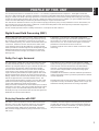
REMOTE CONTROL TRANSMITTER
The remote control transmitter provided with this unit is designed to control all the most commonly used functions of this unit. If the
CD player and tape deck connected to this unit are YAMAHA components designed for remote control compatibility, then this
remote control transmitter will also control various functions of each component.
REC/PAUSE
DIR BDIR A
PLAY
DISC
POWER VOLUME
PLAY
PRESET
A/B/C/D/E
–+
TEST
TIME
/KEY
DELAY
/KEY
EFFECT
PROGRAM
PROLOGIC
3 STEREO
–+
SLEEP
TAPE
A/B
ON/OFF
TUNER
CD
PHONO
VIDEO
VCR
2
3
4
2
8
9
6
7
5
1
1

15
English
Notes about the remote control transmitter
Battery installation
Battery replacement
If you find that the remote control transmitter must be used
closer to the main unit, the batteries are weak. Replace both
batteries with new ones.
Notes
●
Use only AA, R6, UM-3 batteries for replacement.
●
Be sure the polarities are correct. (See the illustration inside
the battery compartment.)
●
Remove the batteries if the remote control transmitter will not
be used for an extended period of time.
●
If batteries leak, dispose of them immediately. Avoid
touching the leaked material or letting it come in contact with
clothing, etc. Clean the battery compartment thoroughly
before installing new batteries.
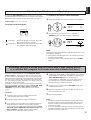
Remote control transmitter operation range
Notes
●
There should be no large obstacles between the remote
control transmitter and the main unit.
●
If the remote control sensor is directly illuminated by strong
lighting (especially an inverter type of fluorescent lamp etc.),
it might cause the remote control transmitter not to work
correctly. In this case, reposition the main unit to avoid direct
lighting.
1
3
2
30°
30°
Remote control sensor
Within approximately
6 m (19.7 feet)
For Other Component Control
Identify the remote control transmitter keys with your
component’s keys. If these keys are identical, their functions
will be the same. On each key function, refer to the
corresponding instruction on your component’s manual.
1 Tape deck keys
Controls tape deck.
* DIR A, B and A/B are applicable only to double
cassette tape deck.
* For a single cassette deck with automatic reverse
function, pressing DIR A will reverse the direction of
tape running.
2 CD player keys
Controls compact disc player.
* DISC is applicable only to compact disc changer.

16
DISPLAY PANEL
PRESET
kHz
MHz
MEMORY
AUTO
TAPE MON
STEREO
0
20
l00
ms
PRO LOGIC
3 STEREO HALL
VOCAL AIDLIVE HOUSE
ONE TOUCH KARAOKE
SLEEP
NORMAL WIDE
PHANTOM
EFFECT OFF
12356
9
B
0A
78
4
1 Multi-information display
Displays various information, for example station frequency,
preset station number and name of selected input source.
2 STEREO indicator
Lights up when an FM stereo broadcast with sufficient signal
strength is received.
3 Signal-level meter
Indicates the signal level of the received station.
If multipath interference is detected, the indication decreases.
4 SLEEP indicator
Lights up while the built-in SLEEP timer is functioning.
5 Center channel mode indicators
The name of a selected center channel mode lights up only
when the DSP program, PRO LOGIC or 3 STEREO is
selected.
6 EFFECT OFF indicator
Lights up if the digital sound field processor including the Dolby
Pro Logic Surround decoder is turned off by pressing the
SUR/KARAOKE EFFECT button on the front panel or the
EFFECT ON/OFF key on the remote control transmitter when
a normal DSP program ( PRO LOGIC, 3 STEREO,
LIVE HOUSE or HALL) is selected. In this state, sound output
is 2-channel stereo.
7 MEMORY indicator
When the MEMORY button is pressed, this indicator flashes
for about 5 seconds. During this period, the displayed station
can be programmed to the memory by using the A/B/C/D/E
button and the preset station number selector buttons.
8 AUTO indicator
Lights up when this unit is in the automatic tuning mode.
9 TAPE MON indicator
Lights up when the tape deck (or MD recorder etc.) is selected
as the input source by pressing the TAPE (MD) MONITOR
button.
0 DSP program indicators
When a normal DSP program ( PRO LOGIC, 3
STEREO, LIVE HOUSE or HALL) is selected, its name lights
up.
A ONE TOUCH KARAOKE indicator
Lights up by pressing the ONE TOUCH KARAOKE button on
the front panel. In this mode, you can select one of three audio
output modes according as you prefer. If you select the
“VOCAL CUT” mode, medium frequencies (vocals, etc.) of the
playing source sound are attenuated.
To extinguish this indicator, press the ONE TOUCH
KARAOKE button once or more.
B VOCAL AID indicator
Lights up by pressing the VOCAL AID button on the front
panel. In this mode, you can select one of three audio output
modes according as you prefer. If you select the “VOCAL
CUT” mode, medium frequencies (vocals, etc.) of the playing
source sound are attenuated only when there is an input from
the microphone(s).
To extinguish this indicator, press the VOCAL AID button once
or more.

17
English
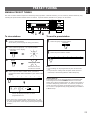
1
Set to the “
∞
” position.
2 Turn the power on.
3 Select the main speakers to be used.
* If you use two main speaker systems, press both the A
and B switches.
4
Set to the “0” position.
5
6 Select the center channel output mode suitable for your
speaker configuration.
(Refer to “SPEAKER CONFIGURATION” on page 6.)
On the feature of each mode, refer to the “Note” shown
below.
Note
In step 6, when you select a center channel output mode,
note the following.
For 5 speaker configuration)
NORMAL: Select this mode when you use a center speaker
that is smaller than the main speakers. In this
mode, the bass tone will be output from the main
speakers.
WIDE: Select this mode when you use the center
speaker approximately same sized as the main
speakers.
For 4 speaker configuration)
PHANTOM: Select this mode when you do not use the center
speaker. The center sound will be output from
the left and right main speakers.
* When the DOLBY 3 STEREO program is used, the
“PHANTOM” mode cannot be selected.
SPEAKER BALANCE ADJUSTMENT
This procedure lets you adjust the sound output level balance between the main, center, and rear speakers using the built-in test
tone generator. When this adjustment is performed, the sound output level heard at the listening position will be the same from
each speaker. This is important for the best performance of the digital sound field processor and the Dolby Pro Logic Surround
decoder.
SPEAKERS
A
ON
OFF
B
BASS TREBLE
55
4
3
2
l
0
l
2
3
4
55
4
3
2
l
0
l
2
3
4
BALANCE
55
4
3
2
l
0
l
2
3
4
LR
l6
20
28
40
60
l2
8
4
2
0
–dB
VOLUME
POWER
REC/PAUSE
DIR BDIR A
PLAY
DISC
POWER VOLUME
PLAY
PRESET
A/B/C/D/E
–+
TEST
TIME
/KEY
DELAY
/KEY
EFFECT
PROGRAM
PROLOGIC
3 STEREO
–+
SLEEP
TAPE
A/B
ON/OFF
TUNER
CD
PHONO
VIDEO
VCR
1
2
3
POWER
SPEAKERSPHONES
A
ON
B
OFF
BASS TREBLE BALANCE
VOLUME
55
4
3
2
l
0
l
2
3
4
55
4
3
2
l
0
l
2
3
4
LR
l6
20
28
40
60
l2
8
4
2
0
–dB
55
4
3
2
l
0
l
2
3
4
FM
/
AM
MAN'L
/
AUTO FM
TUNING
MODE
AUTO
/
MAN’L MONO
ONE TOUCH
KARAOKE
DOWN
TUNING
UP VOCAL AID
MEMORY
EDIT
KEY CONTROL
A
/
B
/
C
/
D
/
E
1
2 3 4 5 6 7 8
TAPE (MD)
MONITOR
VIDEOVCR
TUNER
CD
PHONO
MIN MAX
REAR
LEVEL
CENTER
LEVEL
0l0 0l0
PRO LOGIC 3 STEREO
SUR/KARAOKE
EFFECT
BALLAD
POPS
JAZZ
LIVE HOUSE
CENTER
MODEHALL
ROCK
MIN MAX
ECHO
LEVEL
MIC 2MIC 1
KARAOKE
6
4
5
TEST
CONTINUED
CENTER
MODE
NORMAL
WIDE
PHANTOM

7 Turn up the volume.
You will hear a test tone (like pink noise) from the left main
speaker, then the center speaker, then the right main
speaker, and then the rear speakers, for about two seconds
each. The display changes as shown below.
* The test tone from the left rear speaker and the right
rear speaker will be heard at the same time.
8 Adjust the BALANCE control so that the effect sound
output level of the left main speaker and the right main
speaker are the same.
9 Adjust the sound output levels of the center speaker
and the rear speakers so that they become almost as
same as that of the main speakers.
10 Cancel the test tone.
Notes
●
Once you have completed these adjustments, you can
adjust whole sound level on your audio system by using the
VOLUME control (or the VOLUME keys on the remote
control transmitter) only.
●
If you use external power amplifiers, you may also use their
volume controls to achieve proper balance.
●
In step 9, if the center channel mode is in the “PHANTOM”
position, the sound output level of the center speaker
cannot be adjusted. This is because in this mode, the
center sound is automatically output from the left and right
main speakers.
18
Disappears.
TEST
CENTER
LEVEL
0l0
REAR
LEVEL
0l0
POWER
SPEAKERSPHONES
A
ON
B
OFF
BASS TREBLE BALANCE
VOLUME
55
4
3
2
l
0
l
2
3
4
55
4
3
2
l
0
l
2
3
4
LR
l6
20
28
40
60
l2
8
4
2
0
–dB
55
4
3
2
l
0
l
2
3
4
FM
/
AM
MAN'L
/
AUTO FM
TUNING
MODE
AUTO
/
MAN’L MONO
ONE TOUCH
KARAOKE
DOWN
TUNING
UP VOCAL AID
MEMORY
EDIT
KEY CONTROL
A
/
B
/
C
/
D
/
E
1
2 3 4 5 6 7 8
TAPE (MD)
MONITOR
VIDEOVCR
TUNER
CD
PHONO
MIN MAX
REAR
LEVEL
CENTER
LEVEL
0l0 0l0
PRO LOGIC 3 STEREO
SUR/KARAOKE
EFFECT
BALLAD
POPS
JAZZ
LIVE HOUSE
CENTER
MODEHALL
ROCK
MIN MAX
ECHO
LEVEL
MIC 2MIC 1
KARAOKE
l6
20
28
40
60
l2
8
4
2
0
–dB
VOLUME
98
7
BALANCE
55
4
3
2
l
0
l
2
3
4
LR
REC/PAUSE
DIR BDIR A
PLAY
DISC
POWER VOLUME
PLAY
PRESET
A/B/C/D/E
–+
TEST
TIME
/KEY
DELAY
/KEY
EFFECT
PROGRAM
PROLOGIC
3 STEREO
–+
SLEEP
TAPE
A/B
ON/OFF
TUNER
CD
PHONO
VIDEO
VCR
7
Main (L)
Main (R)
Center
Rear (L and R)
10

19
English
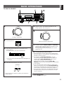
1
Set to the “
∞
” position.
2 Turn the power on.
3 Select the desired input source by using the input
selector buttons.
(For video sources, turn the TV/monitor ON.)
* The name of the selected input source will appear on
the display.
4 Select the main speakers to be used.
* If you use two main speaker systems, press both the A
and B switches.
5 Play the source. (For detailed information on the
tuning operation, refer to page 22.)
6
Adjust to the desired output level.
7 If desired, adjust the BASS, TREBLE and BALANCE
controls (refer to page 21), and use the digital sound
field processor. (Refer to page 27.)
To enjoy singing Karaoke by using this unit, refer to
pages 29 to 31.
Notes on using the input selector buttons
●
Note that pressing on each input selector button selects
the source which is connected to the corresponding input
terminals on the rear panel.
●
The selection of TAPE (MD) MONITOR cannot be
canceled by pressing another input selector button. To
cancel it, press TAPE (MD) MONITOR again so that
“TAPE MON” disappears from the display.
When you select a button other than TAPE (MD)
MONITOR, make sure that “TAPE MON” is not illuminated
on the display.
●
If you select the input selector button for a video source
without canceling the selection of TAPE (MD) MONITOR,
the playback result will be the video image from the video
source and the sound from the audio tape (or MD etc.).
●
Once you play a video source, its video image will not be
interrupted even if the input selector button for an audio
source is selected.
To turn off the power
Press the POWER switch again.
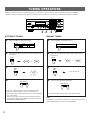
BASIC OPERATIONS
TO PLAY A SOURCE
l6
20
28
40
60
l2
8
4
2
0
–dB
VOLUME
SPEAKERS
A
ON
OFF
B
l6
20
28
40
60
l2
8
4
2
0
–dB
VOLUME
TUNER
CD
PHONO
POWER
1, 6
2
4
7
POWER
SPEAKERSPHONES
A
ON
B
OFF
BASS TREBLE BALANCE
VOLUME
55
4
3
2
l
0
l
2
3
4
55
4
3
2
l
0
l
2
3
4
LR
l6
20
28
40
60
l2
8
4
2
0
–dB
55
4
3
2
l
0
l
2
3
4
FM
/
AM
MAN'L
/
AUTO FM
TUNING
MODE
AUTO
/
MAN’L MONO
ONE TOUCH
KARAOKE
DOWN
TUNING
UP VOCAL AID
MEMORY
EDIT
KEY CONTROL
A
/
B
/
C
/
D
/
E
1
2 3 4 5 6 7 8
TAPE (MD)
MONITOR
VIDEOVCR
TUNER
CD
PHONO
MIN MAX
REAR
LEVEL
CENTER
LEVEL
0l0 0l0
PRO LOGIC 3 STEREO
SUR/KARAOKE
EFFECT
BALLAD
POPS
JAZZ
LIVE HOUSE
CENTER
MODEHALL
ROCK
MIN MAX
ECHO
LEVEL
MIC 2MIC 1
KARAOKE
7
3

20
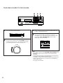
1 Select the source to be recorded.
2 Play the source and then turn the VOLUME control up
to confirm the input source. (For detailed information
on the tuning operations, refer to the page 22.)
3 Begin recording on the tape deck (or MD recorder etc.)
or VCR connected to this unit.
4 If the tape deck (or MD recorder etc.) is used for
recording, you can monitor the sounds being recorded
by pressing TAPE (MD) MONITOR so that “TAPE
MON” lights up on the display.
Notes
• The settings of DSP and the VOLUME, BASS, TREBLE and
BALANCE controls have no effect on the material being
recorded.
• You can also record your vocal input from the microphone(s)
connected to this unit along with the source.
In addition, an effect sound of DSP program for Karaoke and
effects of Karaoke functions can also be recorded with the
vocal and the source.
(See page 31 for details.)
l6
20
28
40
60
l2
8
4
2
0
–dB
VOLUME
TO RECORD A SOURCE TO TAPE (OR MD)
TUNER
CD
PHONO
2
POWER
SPEAKERSPHONES
A
ON
B
OFF
BASS TREBLE BALANCE
VOLUME
55
4
3
2
l
0
l
2
3
4
55
4
3
2
l
0
l
2
3
4
LR
l6
20
28
40
60
l2
8
4
2
0
–dB
55
4
3
2
l
0
l
2
3
4
FM
/
AM
MAN'L
/
AUTO FM
TUNING
MODE
AUTO
/
MAN’L MONO
ONE TOUCH
KARAOKE
DOWN
TUNING
UP VOCAL AID
MEMORY
EDIT
KEY CONTROL
A
/
B
/
C
/
D
/
E
1
2 3 4 5 6 7 8
TAPE (MD)
MONITOR
VIDEOVCR
TUNER
CD
PHONO
MIN MAX
REAR
LEVEL
CENTER
LEVEL
0l0 0l0
PRO LOGIC 3 STEREO
SUR/KARAOKE
EFFECT
BALLAD
POPS
JAZZ
LIVE HOUSE
CENTER
MODEHALL
ROCK
MIN MAX
ECHO
LEVEL
MIC 2MIC 1
KARAOKE
14
TAPE (MD)
MONITOR
VCR
TUNER PHONO
La pagina sta caricando ...
La pagina sta caricando ...
La pagina sta caricando ...
La pagina sta caricando ...
La pagina sta caricando ...
La pagina sta caricando ...
La pagina sta caricando ...
La pagina sta caricando ...
La pagina sta caricando ...
La pagina sta caricando ...
La pagina sta caricando ...
La pagina sta caricando ...
La pagina sta caricando ...
La pagina sta caricando ...
La pagina sta caricando ...
La pagina sta caricando ...
-
 1
1
-
 2
2
-
 3
3
-
 4
4
-
 5
5
-
 6
6
-
 7
7
-
 8
8
-
 9
9
-
 10
10
-
 11
11
-
 12
12
-
 13
13
-
 14
14
-
 15
15
-
 16
16
-
 17
17
-
 18
18
-
 19
19
-
 20
20
-
 21
21
-
 22
22
-
 23
23
-
 24
24
-
 25
25
-
 26
26
-
 27
27
-
 28
28
-
 29
29
-
 30
30
-
 31
31
-
 32
32
-
 33
33
-
 34
34
-
 35
35
-
 36
36


Yamaha R-302 Manuale utente
- Categoria
- Sintonizzatori audio
- Tipo
- Manuale utente
in altre lingue
- English: Yamaha R-302 User manual
- français: Yamaha R-302 Manuel utilisateur
- español: Yamaha R-302 Manual de usuario
- Deutsch: Yamaha R-302 Benutzerhandbuch
- русский: Yamaha R-302 Руководство пользователя
- Nederlands: Yamaha R-302 Handleiding
- português: Yamaha R-302 Manual do usuário
- dansk: Yamaha R-302 Brugermanual
- čeština: Yamaha R-302 Uživatelský manuál
- polski: Yamaha R-302 Instrukcja obsługi
- svenska: Yamaha R-302 Användarmanual
- Türkçe: Yamaha R-302 Kullanım kılavuzu
- suomi: Yamaha R-302 Ohjekirja
- română: Yamaha R-302 Manual de utilizare
Documenti correlati
-
Yamaha RX-300 Manuale del proprietario
-
-
-
-
-
-
-
-
-