De Dietrich DHT386XP1 Manuale del proprietario

Categoria
Cappe da cucina
Tipo
Manuale del proprietario

Questo manuale è adatto anche per

Istruzioni per l'uso e l'installazione
Directions for use and instructions for installation
Notice d'utilisation et d'installation
Gebrauchs- und Installationsanweisung
Gebruiks- en installatie-aanwijzing
Cappa decorativa
Decorative hoods
Hottes décoratives
Wand-Dekorhauben
Decoratieve wandkappen
DHT386XP1
3IT
INDICE
Gentile Signora, Caro Signore,
Se seguirà con cura le raccomandazioni
contenute in questo Libretto Istruzioni,
la sua Cappa si manterrà efficiente nel tempo
e le consentirà di ottenere costantemente
le migliori prestazioni.
CONSIGLI E SUGGERIMENTI 4
CARATTERISTICHE 5
INSTALLAZIONE 6
USO 8
MANUTENZIONE 9
4IT
CONSIGLI E SUGGERIMENTI
INSTALLAZIONE
Il produttore declina qualsiasi responsabilità per danni dovuti ad
installazione non corretta o non conforme alle regole dell’arte.
La distanza minima di sicurezza tra il Piano di cottura e la Cappa
deve essere di 650 mm.
Verificare che la tensione di rete corrisponda a quella riportata
nella targhetta posta all’interno della Cappa.
Per Apparecchi in Classe I
a
accertarsi che l’impianto elettrico do-
mestico garantisca un corretto scarico a terra.
Collegare la Cappa al Condotto di scarico con tubazione di dia-
metro pari o superiore a 120 mm. Il percorso della tubazione deve
essere il più breve possibile.
Non collegare la Cappa a condotti di scarico dei fumi prodotti da
combustione (caldaie, caminetti, ecc.).
Nel caso in cui nella stanza vengano utilizzati sia la Cappa che
Apparecchi non azionati da energia elettrica (ad esempio Appa-
recchi utilizzatori di gas), si deve provvedere ad una aerazione
sufficiente dell’ambiente. Se la cucina ne fosse sprovvista, prati-
care un’apertura che comunichi con l’esterno, per garantire il ri-
chiamo d’aria pulita.
USO
La Cappa è stata progettata esclusivamente per Uso domestico,
per abbattere gli Odori della cucina.
Non fare mai uso improprio della Cappa.
Non lasciare fiamme libere a forte intensità sotto la Cappa in fun-
zione.
Regolare sempre le fiamme in modo da evitare una evidente fuo-
riuscita laterale delle stesse rispetto al fondo delle pentole.
Controllare le friggitrici durante l’Uso: l’olio surriscaldato po-
trebbe infiammarsi.
La Cappa non deve essere utilizzata da bambini o persone non
abilitate all’Uso corretto.
MANUTENZIONE
Prima di procedere a qualsiasi operazione di Manutenzione,
scollegare la Cappa togliendo la spina elettrica o spegnendo l’in-
terruttore generale.
Effettuare una scrupolosa e tempestiva Manutenzione dei Filtri
secondo gli intervalli consigliati.
Per la pulizia delle superfici della Cappa è sufficiente utilizzare un
panno umido e detersivo liquido neutro.
650mm.min.
5IT
0
÷
152
280
L
260
150
ø
CARATTERISTICHE
Ingombro
Tipo Cappa 60
L 598
Componenti
Rif. Q.tà Componenti di Prodotto
1 1 Corpo Cappa completo di: Comandi, Luce,
Gruppo Ventilatore, Filtri
8 1 Griglia direzionata Uscita Aria
9 1 Flangia di riduzione ø 150-120 mm
20 1 Profilo chiusura
Rif. Q.tà Componenti di Installazione
12a 4 Viti 4,2 x 44,4
12e 2 Viti 2,9 x 9,5
Q.tà Documentazione
1 Libretto Istruzioni
12e
8
9
1
12a
20
6IT
INSTALLAZIONE
Foratura Piano di supporto e Montaggio Cappa
MONTAGGIO CON VITI
Il Piano di supporto della Cappa deve essere
rientrante di 220 mm dal Piano inferiore dei Pen-
sili.
Forare ø 4,5 mm il supporto utilizzando la Dima
di foratura in dotazione.
Praticare un foro ø 150 mm sul Piano di sup-
porto, utilizzando la Dima di foratura in dota-
zione.
Fissare con 4 Viti
12a12a
12a12a
12a (4,2 x 44,4) in dotazione.
MONTAGGIO CON FISSAGGIO A SCATTO
La Cappa può essere installata direttamente sul
piano inferiore dei Pensili (650 mm min. dal
Piano di Cottura) con i Supporti laterali a scat-
to.
Praticare un incasso sul piano inferiore del Pen-
sile, come indicato.
Inserire la Cappa fino ad agganciare i Supporti
laterali a scatto.
Bloccare definitivamente serrando le Viti
VfVf
VfVf
Vf dal
sotto della Cappa.
220
15
264
L1
Vf
Tipo Cappa 60
L1 598
7IT
PROFILO DI CHIUSURA
Lo spazio tra il bordo della Cappa e la Parete
di fondo può essere chiuso applicando il Pro-
filo
2020
2020
20 in dotazione con le Viti già predispo-
ste a questo scopo.
Connessioni
USCITA ARIA VERSIONE ASPIRANTE
Per installazione in Versione Aspirante collegare la Cappa alla tubazione di uscita per mezzo di
un tubo rigido o flessibile di ø150 o 120 mm, la cui scelta è lasciata all'installatore.
Per collegamento con tubo ø120 mm, inseri-
re la Flangia di riduzione 9 sull'Uscita del Cor-
po Cappa.
Fissare il tubo con adeguate fascette
stringitubo. Il materiale occorrente non è in
dotazione.
Togliere eventuali Filtri Antiodore al Carbo-
ne attivo.
USCITA ARIA VERSIONE FILTRANTE
Praticare un foro ø 150 mm sulla Mensola
soprastante la Cappa.
Collegare l’uscita del Corpo Cappa con la parte
superiore del pensile per mezzo di un tubo rigi-
do di ø 150 mm, la cui scelta è lasciata
all’installatore.
Fissare il tubo con adeguate fascette
stringitubo. Il materiale occorrente non è in
dotazione.
Assicurarsi della presenza dei Filtri Antiodore
al Carbone attivo.
CONNESSIONE ELETTRICA
Collegare la Cappa all’Alimentazione di Rete interponendo un Interruttore bipolare con aper-
tura dei contatti di almeno 3 mm.
Dopo aver installato la cappa è necessario per la prima volta aprire il carrello scorrevole
energicamente fino a sentire lo scatto di fine corsa.
20
9
ø 120
ø 150
8
9
125
8
9
125
12e
8IT
USO
Quadro comandi
LL
LL
L Luce Accende e spegne l’Impianto di Illuminazione.
MM
MM
M Motore Accende e spegne il motore Aspirazione.
V1V1
V1V1
V1 Velocità Diminuisce la velocità di esercizio.
V2V2
V2V2
V2 Velocità Aumenta la velocità di esercizio.
V3V3
V3V3
V3 Velocità Velocità massima, adatta a fronteggiare le massime emissioni di vapore di
intensiva cottura. Si spegne automaticamente dopo 10 minuti dall’entrata in funzione.
Può essere disinserita manualmente premendo il tasto.
SS
SS
S Led Fisso Motore acceso
Lampeggiante Velocità intensiva
RR
RR
R Ricevitore telecomando
TELECOMANDO (OPZIONALE)
Questo apparecchio può essere comandato per
mezzo di un telecomando, alimentato con pile
alcaline zinco-carbone da 1,5 V del tipo standard
LR03-AAA.
Non riporre il telecomando in prossimità di
fonti di calore.
Non disperdere le pile nell’ambiente, deposi-
tarle negli appositi contenitori.
M L
V1 V2
V3 R
S
0-1
0-1
9IT
A
B
MANUTENZIONE
Filtri antigrasso
PULIZIA FILTRI ANTIGRASSO METALLICI
Necessitano di essere lavati almeno ogni
2 mesi circa di utilizzo o più frequente-
mente, per un uso particolarmente inten-
so.
Togliere i Filtri uno alla volta, agendo sugli
appositi agganci.
Lavare i Filtri evitando di piegarli, e la-
sciarli asciugare prima di rimontarli.
Rimontarli facendo attenzione a mantene-
re la Maniglia verso la parte visibile ester-
na.
Filtri antiodore (Versione Filtrante)
Sostituzione
Non sono lavabili nè rigenerabili, vanno so-
stituiti ogni 4 mesi circa di utilizzo o più fre-
quentemente, per un uso particolarmente in-
tenso.
Togliere i Filtri Antigrasso
Rimuovere i Filtri antiodore al Carbone attivo
saturi, come indicato (
AA
AA
A).
Montare i nuovi Filtri, come indicato (
BB
BB
B)
Rimontare i Filtri antigrasso.
Illuminazione
SOSTITUZIONE LAMPADE
Lampade alogene da 20 W.Lampade alogene da 20 W.
Lampade alogene da 20 W.
Togliere le 2 Viti che fissano il Supporto illumi-
nazione e sfilarlo dalla Cappa.
Estrarre la Lampada dal Supporto.
Sostituirla con una nuova di uguali caratteristi-
che, facendo attenzione di inserire correttamente
i due spinotti nella sede del Supporto.
Rimontare il Supporto fissandolo con le due Viti
precedentemente tolte.
10GB
RECOMMENDATIONS AND SUGGESTIONS 11
CHARACTERISTICS 12
INSTALLATION 13
USE 15
MAINTENANCE 16
CONTENTS
Dear Customer,
If you follow the recommendations
contained in this Instruction Manual,
your appliance will give you constant
high performance and will remain
efficient for many years to come.
11GB
RECOMMENDATIONS AND SUGGESTIONS
INSTALLATION
The manufacturer will not be held liable for any damages resulting
from incorrect or improper installation.
The minimum safety distance between the cooker top and the
extractor hood is 650 mm.
Check that the mains voltage corresponds to that indicated on the
rating plate fixed to the inside of the hood.
For Class I appliances, check that the domestic power supply
guarantees adequate earthing.
Connect the extractor to the exhaust flue through a pipe of
minimum diameter 120 mm. The route of the flue must be as short
as possible.
Do not connect the extractor hood to exhaust ducts carrying
combustion fumes (boilers, fireplaces, etc.).
If the extractor is used in conjunction with non-electrical appliances
(e.g. gas burning appliances), a sufficient degree of aeration must
be guaranteed in the room in order to prevent the backflow of
exhaust gas. The kitchen must have an opening communicating
directly with the open air in order to guarantee the entry of clean
air.
USE
The extractor hood has been designed exclusively for domestic
use to eliminate kitchen smells.
Never use the hood for purposes other than for which it has ben
designed.
Never leave high naked flames under the hood when it is in
operation.
Adjust the flame intensity to direct it onto the bottom of the pan
only, making sure that it does not engulf the sides.
Deep fat fryers must be continuously monitored during use:
overheated oil can burst into flames.
The hood should not be used by children or persons not instructed
in its correct use.
MAINTENANCE
Switch off or unplug the appliance from the mains supply before
carrying out any maintenance work.
Clean and/or replace the Filters after the specified time period.
Clean the hood using a damp cloth and a neutral liquid detergent.
650mm.min.
12GB
0
÷
152
280
L
260
150
ø
CHARACTERISTICS
Dimensions
Components
Ref. Q.ty Product Components
1 1 Hood Body, complete with: Controls, Light,
Blower, Filters
8 1 Directional Air Outlet grille
9 1 Reducer Flange ø 150-120 mm
20 1 Closing element
Ref. Q.ty Installation Components
12a 4 Screws 4,2 x 44,4
12e 2 Screws 2,9 x 9,5
Q.ty Documentation
1 Instruction Manual
12e
8
9
1
12a
20
Hood Type 60
L 598
13GB
220
15
264
L1
Vf
Hood Type 60
L1 598
INSTALLATION
Drilling the Support surface and Fitting the Hood
SCREW FITTING
The hood support surface must be 220 mm
above the bottom surface of the wall units.
Drill the support with a ø 4,5 mm drill bit, using
the drilling template provided.
Cut a hole ø 150 mm in size on the support
surface, using the drilling template provided.
Fix using the 4 screws
12a12a
12a12a
12a (4,2 x 44,4) provided.
SNAP-ON FITTING
The hood can be installed either directly on the
bottom surface of the wall units (min. 650 mm
above the hob) using snap-on side supports.
Cut a fitted opening in the bottom surface of
the wall unit, as shown.
Insert the hood until the side supports snap into
place.
Lock in position by tightening the screws
VfVf
VfVf
Vf
from underneath the hood.
14GB
CLOSING ELEMENT
The space between the edge of the hood and
the rear wall can be closed by applying the
element
20 20
20 20
20 provided, using the screws supplied
for this purpose.
Connections
DUCTED VERSION AIR EXHAUST SYSTEM
When installing the ducted version, connect the hood to the chimney using either a flexible or
rigid pipe ø 150 or 120 mm, the choice of which is left to the installer.
To install a ø 120 mm air exhaust connection,
insert the reducer flange 9 on the hood body
outlet.
Fix the pipe in position using sufficient pipe
clamps (not supplied).
Remove any activated charcoal filters.
RECIRCULATION VERSION AIR OUTLET
Cut a hole ø 125 mm in the wall unit over the hood.
Insert the reducer flange 9 on the hood body outlet.
Connect the hood body outlet to the top part of the
wall unit using a rigid or flexible pipe ø120 mm,
to be selected by the installer.
Fix the pipe in position using sufficient pipe clamps
(not supplied).
Fix the directional grille 8 on the recirculation air
outlet using the 2 screws 12e (2,9 x 9,5) provided.
Ensure that the activated charcoal filters have been
inserted.
ELECTRICAL CONNECTION
Connect the hood to the mains through a two-pole switch having a contact gap of at least 3
mm.
When opening the sliding carriage for the first time after installing the hood, pull it out briskly
until it clicks.
20
9
ø 120
ø 150
8
9
125
8
9
125
12e
15GB
USE
Control panel
LL
LL
L Light Switches the lighting system on and off.
MM
MM
M Motor Switches the extractor motor on and off.
V1V1
V1V1
V1 Speed Reduces the operating speed.
V2V2
V2V2
V2 Speed Increases the operating speed.
V3V3
V3V3
V3 Intensive Maximum speed, used for eliminating the highest cooking vapour emission.
speed Switches off automatically after 10 minutes operation. Can also be switched
off manually by pressing the button.
SS
SS
S Led Fixed Motor running led
Flashing Intensive speed led.
RR
RR
R Receiver for Remote Control.
TELECOMANDO (OPZIONALE)
Questo apparecchio può essere comandato per
mezzo di un telecomando, alimentato con pile
alcaline zinco-carbone da 1,5 V del tipo standard
LR03-AAA.
Non riporre il telecomando in prossimità di
fonti di calore.
Non disperdere le pile nell’ambiente, deposi-
tarle negli appositi contenitori.
M L
V1 V2
V3 R
S
0-1
0-1
16GB
MAINTENANCE
Grease filters
CLEANING METAL GREASE FILTERS
The filters must be cleaned every 2
months of operation, or more frequently
for particularly heavy usage.
Remove the filters, one at a time, after
disconnecting the relative fastening
elements.
Wash the filters, taking care not to bend
them. Allow them to dry before refitting.
When refitting the filters, make sure that
the handle is visible on the outside.
Odour filters (Recirculation version)
REPLACING ACTIVATED CHARCOAL FILTERS
These filters are not washable and cannot be
regenerated, and must be replaced
approximately every four months of operation,
or more frequently with heavy usage.
Remove the grease filters.
Remove the saturated activated charcoal
filters, as shown (
AA
AA
A).
Fit new filters (
BB
BB
B), as shown.
Replace the grease filters.
Lighting
LIGHT REPLACEMENT
20 W halogen light.20 W halogen light.
20 W halogen light.
Remove the 2 Screws fixing the Lighting
support, and pull it out of from the Hood.
Extract the Lamp from the Support.
Replace with another of the same type, making
sure that the two pins are properly inserted in
the lamp holder socket holes.
Replace the Support, fixing it in place with the
two Screws removed as above.
A
B
17FR
SOMMAIRE
Chère Madame, Cher Monsieur,
Si vous suivez attentivement les
recommandations contenues dans ce
mode d’emploi, votre hotte restera
toujours efficace, et fournira
constamment les mêmes performances.
CONSEILS ET SUGGESTIONS 18
CARACTERISTIQUES 19
INSTALLATION 20
UTILISATION 22
ENTRETIEN 23
18FR
CONSEILS ET SUGGESTIONS
INSTALLATION
Le fabricant décline toute responsabilité en cas de dommage dû à
une installation non correcte ou non conforme aux règles de l’art.
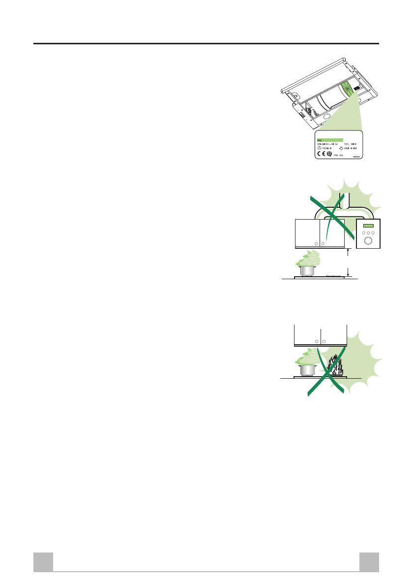
La distance minimale de sécurité entre le plan de cuisson et la
hotte doit être de 650 mm au moins.
Vérifier que la tension du secteur correspond à la valeur qui figu-
re sur la plaquette apposée à l’intérieur de la hotte.
Pour les Appareils appartenant à la Ière Classe, veiller à ce que la
mise à la terre de l’installation électrique domestique ait été
effectuée conformément aux normes en vigueur.
Connecter la hotte à la sortie d’air aspiré à l’aide d’une tuyauterie
d’un diamètre égal ou supérieur à 120 mm. Le parcours de la
tuyauterie doit être le plus court possible.
Eviter de connecter la hotte à des conduites d’évacuation de fumées
issues d’une combustion tel que (Chaudière, cheminée, etc…).
Si vous utilisez des appareils qui ne fonctionnent pas à l’électricité
dans la pièce ou est installée la hotte (par exemple: des appareils
fonctionnant au gaz), vous devez prévoir une aération suffisante
du milieu. Si la cuisine en est dépourvue, pratiquez une ouverture
qui communique avec l’extérieur pour garantir l’infiltration de
l’air pur.
UTILISATION
La hotte a été conçue exclusivement pour l’usage domestique,
dans le but d’éliminer les odeurs de la cuisine.
Ne jamais utiliser abusivement la hotte.
Ne pas laisser les flammes libres à forte intensité quand la hotte
est en service.
Toujours régler les flammes de manière à éviter toute sortie latérale
de ces dernières par rapport au fond des marmites.
Contrôler les friteuses lors de l’utilisation car l’huile surchauffée
pourrait s’enflammer.
La hotte ne doit pas être utilisée par des enfants ou des personnes
ne pouvant pas assurer une utilisation correcte.
ENTRETIEN
Avant de procéder à toute opération d’entretien, retirer la hotte en
retirant la fiche ou en actionnant l’interrupteur général.
Effectuer un entretien scrupuleux et en temps dû des Filtres, à la
cadence conseillée.
Pour le nettoyage des surfaces de la hotte, il suffit d’utiliser un
chiffon humide et détersif liquide neutre.
650mm.min.
19FR
0
÷
152
280
L
260
150
ø
CARACTERISTIQUES
Encombrement
Hotte Type 60
L 598
Composants
Réf. Q.té Composants de Produit
1 1 Corps Hotte équipé de:Comandes,
Lumière,Groupe Ventilateur,Filtres
8 1 Grille orientée Sortie de l ’Air
9 1 Flasque de Réduction ø 150-120 mm
20 1 Profil fermeture
Réf. Q.té Composants pour l ’installation
12a 4 Vis 4,2 x 44,4
12e 2 Vis 2,9 x 9,5
Q.té Documentation
1 Manuel d’instructions
12e
8
9
1
12a
20
20FR
INSTALLATION
Perçage du Plan de support et Montage de la Hotte
MONTAGE AU MOYEN DE VIS
Le Plan de support de la Hotte doit être monté
plus en haut de 220 mm. par rapport au Plan
inférieur des Armoires murales.
Percer un trou de ø 4,5 mm. sur le support, en
utilisant le Gabarit de perçage fourni avec
l’appareil.
Percer un trou de ø 150 mm. sur le Plan de
support, en utilisant le Gabarit de perçage fourni
avec l’appareil.
Fixer à l’aide des 4 Vis
12a12a
12a12a
12a (4,2 x 44,4) fournies
avec l’appareil.
MONTAGE AVEC FIXATION PAR ENCLIQUETAGE
Il est possible d’installer la Hotte directement
sur le plan inférieur des Armoires murales (650
mm. min. par rapport au Plan de Cuisson) au
moyen de supports latéraux par encliquetage.
Effectuer un emboîtage sur le plan inférieur de
l’Armoire murale, comme indiqué.
Insérer la Hotte jusqu’à accrocher les Supports
latéraux par encliquetage.
Bloquer définitivement en serrant les Vis
VfVf
VfVf
Vf
depuis le bas de la Hotte.
15
264
L1
Vf
Type de hotte 60
L1 598
1 / 1

De Dietrich DHT386XP1 Manuale del proprietario

Categoria
Cappe da cucina
Tipo
Manuale del proprietario
Questo manuale è adatto anche per