
CENTRALE DI COMANDO A MICROPROCESSORE PER CANCELLI SCORREVOLI 400V
MICROPROCESSOR CONTROL UNIT FOR SLIDING GATES 400V
ARMOIRE DE COMMANDE À MICROPROCESSEUR POUR PORTAILS COULISSANTS 400V
CENTRAL DE MANDO CON MICROPROCESADOR PARA PORTONES CORREDIZOS 400V
MIKROPROZESSOR-STEUEREINHEIT FÜR SCHIEBETORE 400V
ISTRUZIONI PER L’USO - NORME DI INSTALLAZIONE
INSTRUCTIONS FOR USE - DIRECTIONS FOR INSTALLATION
INSTRUCTIONS - REGLES D’INSTALLATION
INSTRUCCIONES PARA EL USO - NORMAS PARA LA INSTALACION
GEBRAUCHSANLEITUNG - ANWEISUNGEN ZUR INSTALLATION
JA280C

AVVERTENZE PER L’INSTALLATORE
OBBLIGHI GENERALI PER LA SICUREZZA
1) ATTENZIONE! È importante per la sicurezza delle persone seguire
attentamente tutta l’istruzione. Una errata installazione o un errato
uso del prodotto può portare a gravi danni alle persone.
2) L ntamente le istruzioni prima di iniziare l’installazione del prodotto.
3) I materiali dell’imballaggio (plastica, polistirolo, ecc.) non devono
essere lasciati alla portata dei bambini in quanto potenziali fonti di
pericolo.
4) Conservare le istruzioni per riferimenti futuri.
5) Questo prodotto è stato progettato e costruito esclusivamente per
l’utilizzo indicato in questa documentazione. Qualsiasi altro utilizzo
non espressamente indicato potrebbe pregiudicare l’integrità del
prodotto e/o rappresentare fonte di pericolo.
6) GENIUS declina qualsiasi responsabilità derivata dall’uso improprio o
diverso da quello per cui l’automatismo è destinato.
7) Non installare l’apparecchio in atmosfera esplosiva: la presenza di gas
o fumi infiammabili costituisce un grave pericolo per la sicurezza.
8) Gli elementi costruttivi meccanici devono essere in accordo con
quanto stabilito dalle Norme EN 12604 e EN 12605.
Per i Paesi extra-CEE, oltre ai riferimenti normativi nazionali, per
ottenere un livello di sicurezza adeguato, devono essere seguite le
Norme sopra riportate.
9) GENIUS non è responsabile dell’inosservanza della Buona Tecnica
nella costruzione delle chiusure da motorizzare, nonché delle
deformazioni che dovessero intervenire nell’utilizzo.
10) L’installazione deve essere effettuata nell’osservanza delle Norme EN
12453 e EN 12445. Il livello di sicurezza dell’automazione deve essere
C+E.
11) Prima di effettuare qualsiasi intervento sull’impianto, togliere l’alimen-
tazione elettrica.
12) Prevedere sulla rete di alimentazione dell’automazione un interrutto-
re onnipolare con distanza d’apertura dei contatti uguale o superiore
a 3 mm. È consigliabile l’uso di un magnetotermico da 6A con
interruzione onnipolare.
13) Verificare che a monte dell’impianto vi sia un interruttore differenzia-
le con soglia da 0,03 A.
14) Verificare che l’impianto di terra sia realizzato a regola d’arte e
collegarvi le parti metalliche della chiusura.
15) L’automazione dispone di una sicurezza intrinseca antischiacciamento
costituita da un controllo di coppia. E' comunque necessario verificar-
ne la sogli di intervento secondo quanto previsto dalle Norme indicate
al punto 10.
16) I dispositivi di sicurezza (norma EN 12978) permettono di proteggere
eventuali aree di pericolo da Rischi meccanici di movimento, come
ad Es. schiacciamento, convogliamento, cesoiamento.
17) Per ogni impianto è consigliato l’utilizzo di almeno una segnalazione
luminosa nonché di un cartello di segnalazione fissato adeguatamen-
te sulla struttura dell’infisso, oltre ai dispositivi citati al punto “16”.
18) GENIUS declina ogni responsabilità ai fini della sicurezza e del buon
funzionamento dell’automazione, in caso vengano utilizzati compo-
nenti dell’impianto non di produzione GENIUS.
19) Per la manutenzione utilizzare esclusivamente parti originali GENIUS.
20) Non eseguire alcuna modifica sui componenti facenti parte del
sistema d’automazione.
21) L’installatore deve fornire tutte le informazioni relative al funziona-
mento manuale del sistema in caso di emergenza e consegnare
all’Utente utilizzatore dell’impianto il libretto d’avvertenze allegato al
prodotto.
22) Non permettere ai bambini o persone di sostare nelle vicinanze del
prodotto durante il funzionamento.
23) Tenere fuori dalla portata dei bambini radiocomandi o qualsiasi altro
datore di impulso, per evitare che l’automazione possa essere azionata
involontariamente.
24) Il transito tra le ante deve avvenire solo a cancello completamente
aperto.
25) L’Utente utilizzatore deve astenersi da qualsiasi tentativo di riparazio-
ne o d’intervento diretto e rivolgersi solo a personale qualificato.
26) Tutto quello che non è previsto espressamente in queste istruzioni
non è permesso
IMPORTANT NOTICE FOR THE INSTALLER
GENERAL SAFETY REGULATIONS
1) ATTENTION! To ensure the safety of people, it is important that you
read all the following instructions. Incorrect installation or incorrect
use of the product could cause serious harm to people.
2) Carefully read the instructions before beginning to install the product.
3) Do not leave packing materials (plastic, polystyrene, etc.) within
reach of children as such materials are potential sources of
danger.
4) Store these instructions for future reference.
5) This product was designed and built strictly for the use indicated in this
documentation. Any other use, not expressly indicated here, could
compromise the good condition/operation of the product and/or be
a source of danger.
6) GENIUS declines all liability caused by improper use or use other than
that for which the automated system was intended.
7) Do not install the equipment in an explosive atmosphere: the presence
of inflammable gas or fumes is a serious danger to safety.
8) The mechanical parts must conform to the provisions of Standards EN
12604 and EN 12605.
For non-EU countries, to obtain an adequate level of safety, the
Standards mentioned above must be observed, in addition to national
legal regulations.
9) GENIUS is not responsible for failure to observe Good Technique in the
construction of the closing elements to be motorised, or for any
deformation that may occur during use.
10) The installation must conform to Standards EN 12453 and EN 12445. The
safety level of the automated system must be C+E.
11) Before attempting any job on the system, cut out electrical power.
12) The mains power supply of the automated system must be fitted with
an all-pole switch with contact opening distance of 3mm or greater.
Use of a 6A thermal breaker with all-pole circuit break is recommended.
13) Make sure that a differential switch with threshold of 0.03 A is fitted
upstream of the system.
14) Make sure that the earthing system is perfectly constructed, and
connect metal parts of the means of the closure to it.
15) The automated system is supplied with an intrinsic anti-crushing safety
device consisting of a torque control. Nevertheless, its tripping threshold
must be checked as specified in the Standards indicated at point 10.
16) The safety devices (EN 12978 standard) protect any danger areas
against mechanical movement Risks, such as crushing, dragging, and
shearing.
17) Use of at least one indicator-light is recommended for every system,
as well as a warning sign adequately secured to the frame structure,
in addition to the devices mentioned at point “16”.
18) GENIUS declines all liability as concerns safety and efficient operation
of the automated system, if system components not produced by
GENIUS are used.
19) For maintenance, strictly use original parts by GENIUS.
20) Do not in any way modify the components of the automated system.
21) The installer shall supply all information concerning manual operation
of the system in case of an emergency, and shall hand over to the user
the warnings handbook supplied with the product.
22) Do not allow children or adults to stay near the product while it is
operating.
23) Keep remote controls or other pulse generators away from children,
to prevent the automated system from being activated involuntarily.
24) Transit through the leaves is allowed only when the gate is fully open.
25) The user must not attempt any kind of repair or direct action whatever
and contact qualified personnel only.
26) Anything not expressly specified in these instructions is not permitted.
CONSIGNES POUR L'INSTALLATEUR
RÈGLES DE SÉCURITÉ
1) ATTENTION! Il est important, pour la sécurité des personnes, de suivre
à la lettre toutes les instructions. Une installation erronée ou un
usage erroné du produit peut entraîner de graves conséquences
pour les personnes.
2) Lire attentivement les instructions avant d'installer le produit.
3) Les matériaux d'emballage (matière plastique, polystyrène, etc.) ne
doivent pas être laissés à la portée des enfants car ils constituent des
sources potentielles de danger.
4) Conserver les instructions pour les références futures.
5) Ce produit a été conçu et construit exclusivement pour l'usage
indiqué dans cette documentation. Toute autre utilisation non
expressément indiquée pourrait compromettre l'intégrité du produit
et/ou représenter une source de danger.
6) GENIUS décline toute responsabilité qui dériverait d'usage impropre ou
différent de celui auquel l'automatisme est destiné.
7) Ne pas installer l'appareil dans une atmosphère explosive: la présence
de gaz ou de fumées inflammables constitue un grave danger pour
la sécurité.
8) Les composants mécaniques doivent répondre aux prescriptions des
Normes EN 12604 et EN 12605.
Pour les Pays extra-CEE, l'obtention d'un niveau de sécurité approprié
exige non seulement le respect des normes nationales, mais également
le respect des Normes susmentionnées.
9) GENIUS n'est pas responsable du non-respect de la Bonne Technique
dans la construction des fermetures à motoriser, ni des déformations
qui pourraient intervenir lors de l'utilisation.
10) L'installation doit être effectuée conformément aux Normes EN 12453
et EN 12445. Le niveau de sécurité de l'automatisme doit être C+E.
11) Couper l'alimentation électrique avant toute intervention sur
l'installation.
12) Prévoir, sur le secteur d'alimentation de l'automatisme, un interrupteur
omnipolaire avec une distance d'ouverture des contacts égale ou
supérieure à 3 mm. On recommande d'utiliser un magnétothermique
de 6A avec interruption omnipolaire.
13) Vérifier qu'il y ait, en amont de l'installation, un interrupteur différentiel
avec un seuil de 0,03 A.
14) Vérifier que la mise à terre est réalisée selon les règles de l'art et y
connecter les pièces métalliques de la fermeture.
15) L'automatisme dispose d'une sécurité intrinsèque anti-écrasement,
formée d'un contrôle du couple. Il est toutefois nécessaire d'en
vérifier le seuil d'intervention suivant les prescriptions des Normes
indiquées au point 10.

1
ITALIANO
CENTRALE DI COMANDO A MICROPROCESSORE PER CANCELLI SCORREVOLI 400V
ISTRUZIONI PER L’USO - NORME DI INSTALLAZIONE
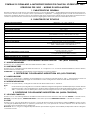
1. CARATTERISTICHE GENERALI
Questa centrale di comando per cancelli scorrevoli con motore trifase 400V~, grazie alla elevata potenza del microproces-
sore di cui è dotata, offre un ampio numero di prestazioni e regolazioni. . I settaggi principali e i modi di funzionamento si
effettuano mediante dip-switch mentre, le regolazioni dei tempi, si effettuano tramite trimmer posti sulla scheda elettronica.
7 LEDS incorporati indicano costantemente lo stato degli ingressi, delle uscite ed eventuali avarie del circuito.
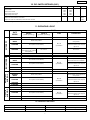
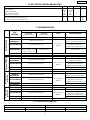
2. CARATTERISTICHE TECNICHE
Tensione di alimentazione
Potenza assorbita
Carico max. motore
Carico max. accessori
Temperatura ambiente
Fusibili di protezione
Logiche di funzionamento
Tempo di apertura / chiusura
Tempo di pausa
Ingressi in morsettiera
400/230 V~ (+6 -10%) - 50/60 Hz.
10 W
2 KW
500 mA
-20°C +50°C
3
Automatica / Semiautomatica /
Automatica con stop / Passo passo con stop
Regolabile tramite trimmer (da 12 a 120 sec.)
Apertura totale / Apertura parziale /
Fotocellule chiusura / Finecorsa apertura-chiusura /
STOP / Alimentazione rete 400/230 V~
Regolabile tramite trimmer (da 0 a 120 sec.)
Connettore per radiocomando
Uscite in morsettiera
Schede radioriceventi
Modi di funzionamento
Comportamento fotocellule chiusura
Funzioni selezionabili con dip-switch
Alimentazione accessori 24 V~ / Lampeggiatore /
Led stato cancello / Motore
90 x 195 x 250 mm.
IP54
Dimensioni contenitore
3. DESCRIZIONE COLLEGAMENTI MORSETTIERA M1 - M2 (ALTA TENSIONE)
3.1 ALIMENTAZIONE 400V
Morsetti “1-2-3” . Collegamento alla rete di alimentazione 400 V~ 50/60 Hz.
3.2 MOTORIDUTTORE
Morsetti “4-5-6”. Collegare il motore trifase ai morsetti T1 - T2 - T3 oppure T1 - T3 - T2 a seconda dell’installazione, destra o sinistra,
del motoriduttore sul cancello.
ATTENZIONE: nel cablaggio già predisposto il motoriduttore è in versione destra.
4. DESCRIZIONE COLLEGAMENTI MORSETTIERA M3 (ALTA TENSIONE)
4.1 LAMPEGGIATORE
Morsetti “7-8” (Fase-Neutro). Utilizzare un lampeggiatore con tensione di funzionamento 230 V~. Alimentando il sistema il
lampeggiatore emetterà un lampeggio a confermare il corretto collegamento della centrale alla rete elettrica.
4.2 ALIMENTAZIONE 230V
Morsetti “9-10” (Fase-Neutro). Collegamento alla rete di alimentazione 230 V~ 50/60 Hz.
Note:
1) Per la messa in opera di guaine e cavi elettrici utilizzare adeguati tubi rigidi e/o flessibili separati per evitare disturbi.
2) Separare sempre i cavi di collegamento degli accessori a bassa tensione da quelli di alimentazione a 230 V~ o a
400V~. Prevedere a monte dell’impianto due interruttori magnetotermici con adeguata soglia di intervento.
5. DESCRIZIONE COLLEGAMENTI MORSETTIERA M4 (BASSA TENSIONE)
5.1 LED STATO CANCELLO
Morsetti “12-13”. Il led di segnalazione visualizza costantemente lo stato ed il moto del cancello. SPENTO = cancello chiuso;
ACCESO = cancello aperto; LAMPEGGIO LENTO = cancello in apertura; LAMPEGGIO VELOCE = cancello in chiusura.
5.2 STOP
Morsetti “14-15” (Circuito Normalmente Chiuso). Lo stato di questo ingresso è segnalato mediante il LED 2. A questo circuito
va collegato qualsiasi dispositivo (es. pulsante, pressostato, ect.) che, aprendo un contatto, arresta il moto del cancello. Si
può usare come sicurezza sul moto di apertura.
Nota bene: Se non vengono collegati dispositivi di STOP ponticellare l’ingresso. Per installare più dispositivi di STOP collegare i
contatti NC in serie.
Grado di protezione del contenitore
Tempo apertura parziale Fisso 10 sec.

2
ITALIANO
5.3 PULSE A - APERTURA TOTALE
Morsetti “14-16” (Circuito Normalmente Aperto). Lo stato di questo ingresso è segnalato mediante il LED 3. A questo circuito
va collegato qualsiasi dispositivo (es. pulsante, radiocomando, ect.) che, chiudendo un contatto, genera un impulso d’aper-
tura e/o chiusura del cancello. Nota bene: Per installare più datori di impulsi collegare i contatti in parallelo.
5.4 PULSE B - APERTURA PARZIALE
Morsetti “14-17” (Circuito Normalmente Aperto). Lo stato di questo ingresso è segnalato mediante il LED 4. A questo circuito
va collegato qualsiasi dispositivo (es. pulsante, radiocomando, ect.) che, chiudendo un contatto, genera un impulso d’aper-
tura e/o chiusura del cancello. L’apertura avviene per 10 secondi fissi.
Nota bene: Per installare più datori di impulsi collegare i contatti in parallelo.
5.5 FOTOCELLULE PROTEZIONE CHIUSURA
Morsetti “18-19” (Circuito Normalmente Chiuso). Lo stato di questo ingresso è segnalato mediante il LED 5. A questo circuito
va collegato qualsiasi dispositivo di sicurezza (fotocellule, pressostato, detector, ect.) che, aprendo un contatto, ha un effetto
di sicurezza sul moto di chiusura. L’effetto è differente in funzione della programmazione effettuata tramite il dip-sw 4.
Nota bene: Per installare più dispositivi di sicurezza collegare i contatti NC in serie.
Nota bene: Se non vengono utilizzati dispositivi di sicurezza ponticellare l’ingresso.
E’ possibile bloccare la richiusura del cancello collegando un orologio timer 24h in serie al circuito delle fotocellule di chiusura.
6. DESCRIZIONE COLLEGAMENTI MORSETTIERA M5 (BASSA TENSIONE)
6.1 FINECORSA APERTURA
Morsetti “20-21” (Circuito Normalmente Chiuso). Lo stato di questo ingresso è segnalato mediante il LED 6. A questo circuito
va collegato il finecorsa di apertura.
6.2 FINECORSA CHIUSURA
Morsetti “21-22” (Circuito Normalmente Chiuso). Lo stato di questo ingresso è segnalato mediante il LED 7. A questo circuito
va collegato il finecorsa di chiusura.
ATTENZIONE: nel caso di errato o mancato collegamento del finecorsa la centrale si inibirà e segnalerà questo stato median-
te il lampeggio ve.loce del LED 1 di diagnosi.
6.3 ALIMENTAZIONE ACCESSORI
Morsetti “23-24” (24 V~). ATTENZIONE: il carico max degli accessori è di 500 mA.
7. INSERIMENTO SCHEDA RICEVITORE PER TELECOMANDO
La centrale è predisposta per alloggiare un modulo radioricevitore monocanale. Per procedere all’installazione togliere
l’alimentazione elettrica e inserire il modulo nell’apposito connettore M6 all’interno della centrale.
Seguire poi le istruzioni del radio-ricevitore per la memorizzazione del telecomando.
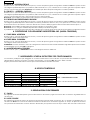
8. LEDS DI CONTROLLO
LEDS
2 - Stop
3 - Pulse A
4 - Pulse B
5 - Fotocellule
6 - Finecorsa apertura
7 - Finecorsa chiusura
ACCESO SPENTO
Comando inattivo
Comando attivato
Comando attivato
Comando attivato
Comando inattivo
Comando inattivo
Sicurezze disimpegnate
Finecorsa libero
Finecorsa libero
Sicurezze impegnate
Finecorsa occupato
Finecorsa occupato
LED 1 Diagnosi
Lento: Funzionamento corretto
Veloce: Circuito dei finecorsa guasto
N.B.: In neretto la condizione dei leds con cancello a riposo.
9. REGOLAZIONI CON TRIMMER
9.1 PAUSA
Per regolare la durata della pausa (per il funzionamento automatico) agire sul trimmer “B”. La durata è regolabile da 0 a
120 secondi.
9.2 APRE/CHIUDE
Per regolare la durata del tempo di apertura/chiusura del cancello agire sul trimmer “C”. La durata è regolabile da 12 a
120 secondi. Nota: Per ottenere la massima efficienza del sistema è necessario regolare un tempo di apertura/chiusura
che permetta di mantenere il motore elettrico alimentato per qualche secondo dopo l’arrivo del cancello sul finecorsa.

3
ITALIANO
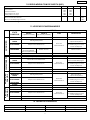
10. REGOLAZIONI CON DIP-SWITCH (SW1)
LOGICHE DI FUNZIONAMENTO
Automatico
Semiautomatico
Automatica con stop
Passo passo con stop
2
13
4
OFF
ON
ON
OFF
OFF
OFF
ON
ON
FUNZIONAMENTO FOTOCELLULA CHIUSURA
Blocca ed inverte il moto
Blocca e al disimpegno inverte
OFF
ON
Nota bene: tutte le regolazioni vanno effettuate a centrale spenta e cancello chiuso.
11. LOGICHE DI FUNZIONAMENTO
STATO
CANCELLO
PULSE A
(apertura totale)
PULSE B
(apertura parziale)
IMPULSI
FOTOCELLULESTOP
CHIUSO
Apre, esegue la pausa e richiude Blocca Pulse Nessun effetto
APERTO IN
PAUSA
Reintegra la pausa
Blocca Pulse e
sospende la pausa
Blocca ed inverte o blocca
e al disimpegno inverte
come da dip-sw 4
Riapre immediatamente
Nessun effetto. Se in
apertura parziale,
apre completamente
Nessun effetto.
IN APERTURA
Nessun effetto.
Blocca il
funzionamento
IN STOP
Chiude immediatamente Nessun effetto / Blocca Pulse
IN CHIUSURA
CHIUSO
Apre, esegue la pausa e richiude Blocca Pulse Nessun effetto
APERTO IN
PAUSA
Richiude immediatamente
Anticipa la chiusura dopo 2
secondi dal disimpegno
Blocca ed inverte o blocca
e al disimpegno inverte
come da dip-sw 4
Riapre immediatamente
IN APERTURA
Nessun effetto.
Blocca il
funzionamento
IN STOP
Chiude immediatamente Nessun effetto / Blocca Pulse
IN CHIUSURA
AUTOMATICO
Richiude immediatamente
SEMIAUTOMATICO
CHIUSO
Apre, esegue la pausa e richiude Blocca Pulse Nessun effetto
APERTO IN
PAUSA
Reintegra la pausa
Blocca ed inverte o blocca
e al disimpegno inverte
come da dip-sw 4
Riapre immediatamente
IN APERTURA
Nessun effetto.
Blocca il
funzionamento
IN STOP
Chiude immediatamente Nessun effetto / Blocca Pulse
IN CHIUSURA
Blocca il funzionamento
AUTOMATICO
CON STOP
CHIUSO
Apre Blocca Pulse Nessun effetto
APERTO
Richiude immediatamente
Blocca ed inverte o blocca
e al disimpegno inverte
come da dip-sw 4
Riapre immediatamente
IN APERTURA
Nessun effetto.
Blocca il
funzionamento
IN STOP
Chiude immediatamente Nessun effetto / Blocca Pulse
IN CHIUSURA
PASSO PASSO
CON STOP
Blocca Pulse e
sospende la pausa
Blocca Pulse
Blocca il funzionamento
FUSIBILE PROTEZIONE FUSIBILE PROTEZIONE
F2 = 1A/250V - 5x20
F1 = 500mA/250V - 5x20
F3 = 315mA/250V - 5x20
Trasformatore
Accessori
Logica
12. FUSIBILI DI PROTEZIONE

4
ITALIANO
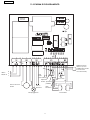
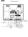
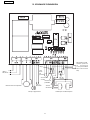
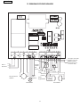
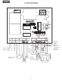
13. SCHEMA DI COLLEGAMENTO
400 V~
50/60 Hz
Motoriduttore
trifase
R
S
T
Lampeggiatore
Stop
Led
stato
cancello
Apertura
totale
Altre
sicurezze
Finecorsa
Fotocellule
Radioricevitore
esterno (se non
si utilizza la scheda
ricevente sul
connettore M6)
Apertura
parziale
230 V~
50/60 Hz

5
ENGLISH
400/230 V~ (+6 -10%) - 50/60 Hz.
10 W
2KW
500 mA
-20°C +50°C
3
Adjustable using trimmer (from 12 to 120 sec.)
90 x 195 x 250 mm.
IP54
MICROPROCESSOR CONTROL UNIT FOR SLIDING GATES 400V
USER INSTRUCTIONS - INSTALLATION STANDARDS
1. GENERAL FEATURES
Thanks to the high-power performance of its built-in microprocessor, this control unit for sliding gates with three-phased 400V
motor offers a wide number of services and adjustments.
The main settings and operating modes can be defined using dip-switches while time adjustments are performed using the
trimmers installed on the electronic circuit board.
7 built-in LEDS constantly display the status of inputs, outputs in addition to any circuit malfunctions.
2. TECHNICAL FEATURES
Power supply
Absorbed power
Max. motor load
Max. load on accessoies
Ambient temperature
Protection fuses
Operating logic
Opening /closing time
Housing degree of protection
Housing dimensions
Functions selected with dip-switches
Terminal board outputs
Radio control connector
Terminal board inputs
Partial opening time
Pause time
Automatic / Semi-automatic /
Automatic with stop / Step-step with stop
Adjustable using trimmer (from 0 to 120 sec.)
Fixed 10 sec.
Total opening / Partial opening /
Closing photocells / Opening-closing limit switch /
STOP / Mains power supply 400/230 V~
Radio receiver boards molex connector
Accessory power supply 24 V~ / Flasher /
Gate status led / Motor
Operating modes
Closing photocell reaction
3. TERMINAL BOARD M1 M2(HIGH VOLTAGE) CONNECTIONS - DESCRIPTION
3.1 400V POWER SUPPLY
Terminals “1 - 2 - 3” . Connection to power supply network 400V~ 50/60 Hz.
3.2 GEAR UNIT
Terminals “4 - 5 - 6” Connect the three-phased motor to terminals T1 - T2 - T3 or T1 - T3 - T2 according to the installation (on the
right or left hand) of the gear motor onto the gate.
WARNING: The gear motor is in the right-hand version in the wiring already provided for.
4. TERMINAL BOARD M3 (HIGH VOLTAGE) CONNECTIONS - DESCRIPTION
4.1 FLASHER
Terminals “7 - 8” (Phase - Neutral). Use a flasher with an operating voltage of 230 V~(100W. max.). When power is supplied to
the system the flasher will blink to confirm that the unit is properly connected to the electric power supply.
4.2 230V POWER SUPPLY
Terminals “9 - 10” (Phase - Neutral). Connection to 230V~ 50/60 Hz power supply network.
Notes:
1) To install sheaths andelectric cables, use adequate separate rigid and/or flexible tubes to avoid interferences.
2) Always separate the low-voltage accessory connection cables from the 230V~ or 400V~ power supply cables.
Two magnetothermal switches with adequate tripping threshold should be provided for upstream of the equipment
5. TERMINAL BOARD M4 (LOW VOLTAGE) CONNECTIONS - DESCRIPTION
5.1 GATE STATUS LED
Terminals “12-13”. The signal led constantly displays gate status and motion. OFF = gate closed; ON = gate open; SLOW FLASHING
= gate opening; FAST FLASHING = gate closing.
5.2 STOP
Terminals “14-15” (Circuit Normally Closed). The status of this input is signalled by LED 2. This circuit is connected to any device
(e.g. button, pressure switch) which, when a contact is opened, can stop the gate motion. It can be used as a safety device
on the opening motion.
Note: If STOP devices are not connected, jumper connect the input. To install multiple STOP devices, connect the NC contacts
in series.

6
ENGLISH
LEDS
2 - Stop
3 - Pulse A
4 - Pulse B
5 - Photocells
6 - Opening limit switch
7 - Closing limit switch
ON OFF
Control deactivated
Safety devices disabled
Limit switch free
LED 1 Diagnostic
Slow: Correct operation
Fast: Failure in the limit switch circuit
Control activated
Control activated
Limit switch free
Control activated
Control deactivated
Control deactivated
Safety devices enabled
Limit switch occupied
Limit switch occupied
5.3 PULSE A - TOTAL OPENING
Terminals “14-16”. (Circuit Normally Open). The status of this input is signalled by LED 3. This circuit is connected to any device
(e.g. button, radio control, etc.) which, when a contact is closed, generates a gate opening and/or closing pulse.
Note: To install multiple pulse devices connect the contacts in parallel.
5.4 PULSE B - PARTIAL OPENING
Terminals “14-17”. (Circuit Normally Open). The status of this input is signalled by LED 4. This circuit is connected to any device
(e.g. button, radio control, etc.) which, when a contact is closed, generates a gate opening and/or closing pulse. The
opening motion is performed for a fixed time of 10 seconds.
Note: To install multiple pulse devices connect the contacts in parallel.
5.5 CLOSING PROTECTION PHOTOCELLS
Terminals “18-19” (Circuit Normally Closed). The status of this input is signalled by LED 5. This circuit is connected to any safety
device (photocells, pressure switch, detector, etc.) which, when a contact is opened, acts as a safety on the closing motion.
The effect will vary depending on the settings performed using dip-sw 4.
Note: To install multiple safety devices connect the NC contacts in series.
Note: If no safety devices are being used, jumper connect the input.
It is possible to prevent the gate from closing by connecting a 24h timer in series to the closing photocell circuit.
6. TERMINAL BOARD M5 (LOW VOLTAGE) CONNECTIONS - DESCRIPTION
6.1 OPENING LIMIT SWITCH
Terminals “20-21” (Circuit Normally Closed). The status of this input is signalled by LED 6. This circuit is connected to the opening
limit switch.
6.2 CLOSING LIMIT SWITCH
Terminals “21-22” (Circuit Normally Closed). The status of this input is signalled by LED 7. This circuit is connected to the closing
limit switch.
WARNING: In case of wrong or missing connection of the limit switch, the control unit will be inhibited and will signal this status
by the fast flashing of the diagnostic LED 1.
6.3 ACCESSORY POWER SUPPLY
Terminals “23-24”. (24 V~). WARNING: the max. load for the accessories is 500 mA.
7. INSERTING THE REMOTE CONTROL RECEIVER BOARD
The unit is designed to house a single-channel radio-receiver module. To install the module, cut off the electric power supply
and insert the module into the special connector M6 inside the unit.
Then follow the instruction coming along with the radio-receiver to store the remote control settings.
Note: Bold is used to indicate the led condition with the gate at rest.
9. ADJUSTMENTS WITH TRIMMER
9.1 PAUSE
To adjust the pause duration (for automatic operation), use trimmer “B”. The duration can be adjusted from 0 to 120 seconds.
9.2 OPEN/CLOSE
To adjust the duration of the gate opening/closing time, use trimmer “C”. The duration can be adjusted from 12 to 120
seconds. Note: To obtain maximum system efficiency, adjust the opening/closing time so that the electric motor can be fed
for a few seconds after the gate has reached the limit switch.
8. CONTROL LEDS

7
ENGLISH
OPERATING LOGIC
Automatic
Semi-automatic
Automatic with stop
Step-step with stop
2
13
4
OFF
ON
ON
OFF
OFF
OFF
ON
ON
CLOSING PHOTOCELL OPERATION
Stops and reverses the motion
Stops and,when released, reverses the motion
OFF
ON
Note: all adjustments are performed with the control unit switched off and the gate closed.
11. OPERATING LOGIC
GATE
STATUS
PULSE A
(total opening)
PULSE B
(partial opening)
PULSES
PHOTOCELLSSTOP
CLOSED
Opens, pauses and closes Blocks Pulse No effect
OPEN IN
PAUSE
Reset the pause
Blocks Pulse and suspends
the pause
Blocks and reverses or stops
and starts after reset as per
dip-sw 4
Re-opens immediately
No effect. If in partial
opening mode, opens
completely
No effect
OPENING
Blocks
operation
STOPPING
Closes immediately No effect / Blocks Pulse
CLOSING
Anticipates closing 2
seconds after the release
AUTOMATIC
SEMI-AUTOMATIC
AUTOMATIC
WITH STOP
Opens
STEP-STEP
WITH STOP
FUSE PROTECTIVE FUSE PROTECTIVE
F2 = 1A/250V - 5x20
F1 = 500mA/250V - 5x20 F3 = 315mA/250V - 5x20
Transformer
Accessories Logics
12. PROTECTIVE FUSES
10. DIP-SWITCH SETTINGS (SW1)
CLOSED
OPEN IN
PAUSE
CLOSING
OPENING
STOPPING
CLOSED
OPEN IN
PAUSE
CLOSING
OPENING
STOPPING
CLOSED
CLOSING
OPENING
STOPPING
OPEN
No effect
Opens, pauses and closes
Re-opens immediately
Re-closes immediately
Re-closes immediately
No effect / Blocks Pulse
No effect
Blocks
operation
Blocks and reverses or stops
and starts after reset as per
dip-sw 4
Blocks Pulse No effect
Closes immediately
Opens, pauses and closes
Reset the pause
Re-opens immediately
Blocks operation
Closes immediately No effect / Blocks Pulse
Blocks
operation
Blocks and reverses or stops
and starts after reset as per
dip-sw 4
No effect
No effectBlocks Pulse
Blocks Pulse and suspends
the pause
Re-closes immediately
Re-opens immediately
Blocks operation
Closes immediately
Blocks Pulse No effect
Blocks Pulse
Blocks and reverses or stops
and starts after reset as per
dip-sw 4
No effect
No effect / Blocks Pulse
Blocks
operation

8
ENGLISH
13. CONNECTION DIAGRAM
400 V~
50/60 Hz
R
S
T
Flasher
Stop
Gate
status
led
Total
opening
Partial
opening
Other safety
devices
Limit switch
Photocells
External radio
receiver (if the
receiving board
is not used on the
M6 connector)
Three-phased reduction gear
230 V~
50/60 Hz

9
FRANÇAIS
400/230 V~ (+6 -10%) - 50/60 Hz.
10 W
2 KW
500 mA
-20°C +50°C
3
Réglable par potentiomètre (de 12 à 120 sec.)
90 x 195 x 250 mm.
IP54
Tension d’alimentation
Puissance absorbée
Puissance maxi moteur
Intansitè maxi accessoires
Température d’utilisation
Fusibles de protection
Logiques de fonctionnement
Temps d’ouverture / fermeture
Degré de protection du coffret
Dimension coffret
Fonctions sélectionnables par micro-interrupteurs
Sorties dans bornier de connexions
Connecteur pour radiocommande
Entrées dans bornier de connexions
Temps d’ouverture partielle
Temps de pause
Automatique / Semi-automatique /
Automatique avec stop / Pas à pas avec stop
Réglable par potentiomètre (de 0 à 120 sec.)
Fixe 10 sec.
Ouverture totale / Ouverture partielle /Cellule photoélectrique
fermeture / Fin de course ouverture-fermeture /
STOP / Alimentation réseau 400/230 V~
Cartes récepteurs radio
Alimentation accessoires 24 V~ / Lampe clignotante /
LED état portail / Moteur
Modes de fonctionnement
Comportement cellule photoélectrique en fermeture
ARMOIRE DE COMMANDE À MICROPROCESSEUR POUR PORTAILS COULISSANTS 400V
INSTRUCTIONS - REGLES D’INSTALLATION
1. CARACTÉRISTIQUES GÉNÉRALES
Grâce à la puissance élevée du microprocesseur dont elle est dotée, cette armoire de commande pour portails coulissants
avec moteur triphasé 400V~ offre un grand nombre de services et réglages. Les réglages principaux et les modes de
fonctionnement s’effectuent par micro-interrupteurs à positions multiples (dip-switch), tandis que les réglages des temps
s’effectuent par potentiomètre placés sur la carte électronique. 7 LEDS incorporées indiquent constamment l’état des entrées,
des sorties et les éventuelles avaries du circuit.
2. CARACTÉRISTIQUES TECHNIQUES
3. DESCRIPTION CONNEXIONS BORNIER M1 - M2 (HAUTE TENSION)
3.1 ALIMENTATION 400V
Bornes “1-2-3” . Connexion au réseau d’alimentation 400 V~ 50/60 Hz.
3.2 MOTORÉDUCTEUR
Bornes “4-5-6”. Connecter le moteur triphasé aux bornes T1 - T2 - T3 ou bien T1 - T3 - T2 selon l’installation, à droite ou à gauche
du motoréducteur sur le portail.
AVIS: dans le câblage prévu, le motoréducteur est en version à droite.
4. DESCRIPTION CONNEXIONS BORNIER M3 (HAUTE TENSION)
4.1 CLIGNOTEUR
Borne “7-8” (Phase-Neutre). Utiliser un clignoteur avec tension de fonctionnement 230 V~. A l’alimentation du système, le
clignoteur émettra un clignotement pour confirmer la connexion correcte de l’armoire au réseau électrique.
4.2 ALIMENTATION 230V
Bornes “9-10” (Phase-Neutre). Connexion au réseau d’alimentation 230 V~ 50/60 Hz.
Notes:
1) Pour la pose de gaines et câbles électriques, utiliser des tubes rigides et/ou flexibles adéquats, séparés pour éviter
les perturbations.
2) Toujours séparer les câbles de connexion des accessoires à basse tension de ceux d’alimentation à 230 V~ ou à
400V~.Prévoir en amont de l’installation deux interrupteurs magnétothermiques avec seuil d’intervention adéquat
5. DESCRIPTION CONNEXIONS BORNIER M4 (BASSE TENSION)
5.1 LED ÉTAT PORTAIL
Bornes “12-13”. La Led de signalisation visualise constamment l’état et le mouvement du portail: ÉTEINT = portail fermé: ALLUMÉ
= portail ouvert: CLIGNOTEMENT LENT = portail en ouverture, CLIGNOTEMENT RAPIDE = portail en fermeture.
5.2 STOP
Bornes “14-15” (Circuit Normalement Fermé) L’état de cette entrée est signalé par la LED 2. Tout dispositif (ex: poussoir,
pressostat, etc.) qui, ouvrant un contact, arrête le mouvement du portail, sera connecté à ce circuit. Il peut être utilisé
comme sécurité sur le mouvement d’ouverture.
Nota bene: Si aucun dispositif de STOP n’est connecté, shunter l’entrée. Pour installer plusieurs dispositifs de STOP connecter les
contacts NC en série.

10
FRANÇAIS
LED
2 - Arrêt
3 - Impulsion A
4 - Impulsion B
5 - Cellules photoélectr.
6 - Fin course ouverture
7 - Fin course fermeture
ALLUMEE ETEINTE
Commande inactive
Sécurités désengagées
Fin de course libre
LED 1 Diagnostic
Lent: Fonctionnement correct
Rapide: Circuit du fin de course en avarie
Commande activée
Commande activée
Fin de course libre
Commande activée
Commande inactive
Commande inactive
Sécurités engagées
Fin de course occupé
Fin de course occupé
5.3 IMPULSION A - OUVERTURE TOTALE
Bornes “14-16” (Circuit Normalement Ouvert). L’état de cette entrée est signalé par la LED 3. Tout dispositif (ex: poussoir,
radioguidage, etc.) qui, en fermant un contact donne une impulsion d’ouverture et/ou fermeture du portail, sera connecté
à ce circuit. Nota bene: Pour installer plusieurs donneurs d’impulsions, connecter les contacts en parallèle.
5.4 IMPULSION B - OUVERTURE PARTIELLE
Bornes “14-17” (Circuit Normalement Ouvert). L’état de cette entrée est signalé par la LED 4. Tout dispositif (ex: poussoir,
radioguidage, etc.) qui, en fermant un contact, donne une impulsion d’ouverture et/ou fermeture du portail, sera connecté
à ce circuit. L’ouverture s’effectue en 10 secondes fixes.
Nota bene: Pour installer plusieurs donneurs d’impulsions, connecter les contacts en parallèle.
5.5 CELLULES PHOTOÉLECTRIQUES PROTECTION FERMETURE
Bornes “18-19” (Circuit Normalement Fermé). L’état de cette entrée est signalé par la LED 5. Tout dispositif de sécurité (cellules
photoélectriques, pressostat, détecteur, etc.) qui en ouvrant un contact a un effet de sécurité sur le mouvement de fermeture,
sera connecté à ce circuit. L’effet diffère en fonction de la programmation effectuée par le dip-sw 4.
Nota bene: Pour installer plusieurs dispositifs de sécurité, connecter les contacts NC en série.
Nota bene: Si les dispositifs de sécurité ne sont pas utilisés, shunter l’entrée.
Il est possible de bloquer la refermeture du portail en connectant une horloge 24h en série au circuit des cellules photoélectriques
de fermeture.
6. DESCRIPTION CONNEXIONS BORNIER M5 (BASSE TENSION)
6.1 FIN DE COURSE OUVERTURE
Bornes “20-21” (Circuit Normalement Fermé). L’état de cette entrée est signalé par la LED 6. Le fin de course d’ouverture doit
être connecté à ce circuit.
6.2 FIN DE COURSE FERMETURE
Bornes “21-22” (Circuit Normalement Fermé). L’état de cette entrée est signalé par la LED 7. Le fin de course de fermeture doit
être connecté à ce circuit.
AVIS : en cas de défaut de connexion ou mauvaise connexion du fin de course, l’armoire de commande sera désactivée et
signalera cet état par clignotement rapide de la LED 1 de diagnostic.
6.3 ALIMENTATION ACCESSOIRES
Bornes “23-24” (24 V~). ATTENTION : la charge max. des accessoires est de 500 mA.
7. MONTAGE CARTE RECEPTRICE RADIOCOMMANDE
L’armoire est prévue pour logement d’un module récepteur radio monocanal. Pour procéder à l’installation, couper
l’alimentation électrique et introduire le module dans le connecteur relatif M6 à l’intérieur de l’armoire.
Suivre ensuite les instructions relatives au récepteur radio pour la mémorisation de la télécommande.
N.B.: en caractères gras : condition des LED avec le pourtail au repos.
9. REGLAGES PAR POTENTIOMETRES
9.1 PAUSE
Pour régler la durée de la pause (pour le fonctionnement automatique) actionner le trimmer “B”. La durée est réglable de
0 à 120 secondes.
9.2 OUVRE/FERME
Pour régler la durée du temps d’ouverture/fermeture du portail, actionner le trimmer “C”. La durée est réglable de 12 à
120 secondes Note: Pour une efficience maximum du système, il est nécessaire de régler un temps d’ouverture/fermeture
permettant de maintenir le moteur électrique alimenté quelques secondes encore après l’arrivée du portail sur le fin de
course.
8. LED DE CONTRÔLE

11
FRANÇAIS
LOGIQUES DE FONCTIONNEMENT
Automatique
Semi-automatique
Automatique avec stop
Pas à pas avec stop
2
13
4
OFF
ON
ON
OFF
OFF
OFF
ON
ON
FONCTIONNEMENT CELLULE PHOTOELECTRIQUE EN FERMETURE
Bloque et inverse le mouvement
Bloque et inverse au dégagement
OFF
ON
ETAT DU
PORTAIL
Impulsion A
(ouverte totale)
Impulsion B
(ouverture partialle)
IMPULSION
CELLULES PHOTO
ELECTRIQUES EN FERMETURE
STOP
FERME
Ouvre, effectue la pause et referme Bloque Impulsion Aucun effet
OUVERT EN
PAUSE
Relance le temps de pause
Bloque Impulsion et suspend
le temps de pause
Selon position micro-interrupteur 4:
bloque et inverse le mouvement;
bloque et rétablit le mouvement
apres désengagement
Réouvre immédiatement
Aucun effet. Si en ou-
verture partielle, ouvre
complètement
Aucun effet
EN OUVERTURE
Bloque le
fonctionnement
EN STOP
Aucun effet / Bloque Impulsion
EN FERMETURE
Avance la fermeture à 2
secondes après le dégagement
AUTOMATIQUE
SEMI-
AUTOMATIQUE
AUTOMATIQUE
AVEC STOP
Ouvre
PAS à PAS
AVEC STOP
FUSIBLE PROTECTION FUSIBLE PROTECTION
F2 = 1A/250V - 5x20
F1 = 500mA/250V - 5x20 F3 = 315mA/250V - 5x20
Trasformateur
Accessories Logique
12. FUSIBLES DE PROTECTION
10. REGLAGES PAR MICRO-INTERRUPTEURS A POSITION MULTIPLES (SW1)
OUVERT
Ouvre
Ferme
Aucun effet
Nota bene: tous les réglages doivent être effectués platine non alimentée et portail fermé.
11. LOGIQUES DE FONCTIONNEMENT
FERME
OUVERT EN
PAUSE
EN FERMETURE
EN OUVERTURE
EN STOP
FERME
OUVERT EN
PAUSE
EN FERMETURE
EN OUVERTURE
EN STOP
FERME
EN FERMETURE
EN OUVERTURE
EN STOP
Ferme immédiatement
Bloque Impulsion Aucun effet
Bloque le
fonctionnement
Selon position micro-interrupteur 4:
bloque et inverse le mouvement;
bloque et rétablit le mouvement
apres désengagement
Aucun effet
Aucun effet / Bloque Impulsion
Réouvre immédiatement
Referme immédiatement
Ferme immédiatement
Ouvre, effectue la pause et referme
Relance le temps de pause
Réouvre immédiatement
Ferme immédiatement
Bloque le fonctionnement
Bloque Impulsion Aucun effet
Bloque le
fonctionnement
Selon position micro-interrupteur 4:
bloque et inverse le mouvement;
bloque et rétablit le mouvement
apres désengagement
Aucun effet / Bloque Impulsion
Aucun effet
Bloque Impulsion et suspend
le temps de pause
Ferme
Réouvre immédiatement
Bloque le fonctionnement
Ferme immédiatement
Bloque le
fonctionnement
Bloque Impulsion Aucun effet
Aucun effet / Bloque Impulsion
Aucun effet
Selon position micro-interrupteur 4:
bloque et inverse le mouvement;
bloque et rétablit le mouvement
apres désengagement
Bloque Impulsion

12
FRANÇAIS
13. SCHEMA DE CONNEXION
400 V~
50/60 Hz
Lampe clignotante
Motoréducteur triphasé
Stop
Led
état
du
portail
Ouverture
totale
Ouverture
partialle
Autres
sécurités
Fin de
course
Cellules photoélectriques
Récepteur radio
externe (si la car-
te receptrice
n’est pas utilisée
sur le connecteur
M6)
T
S
R
230 V~
50/60 Hz

13
ESPAÑOL
400/230 V~ (+6 -10%) - 50/60 Hz.
10 W
2 KW
500 mA
-20°C +50°C
3
Ajustable mediante trimmer (de 12 a 120 seg.)
90 x 195 x 250 mm.
IP54
Tensiòn de alimentaciòn
Potencia consumida
Carga màx. del motor
Carga màx de los accesorios
Temperatura ambiente
Fusibles de protecciòn
Lògicas de funcionamiento
Tiempo de apertura / cierre
Grado de protecciòn del contenedor
Dimensiones del contenedor
Funciones seleccionables con dip-switches
Salidas de la regleta de bornes
Conector para control remoto
Entrada en regleta de bornes
Tiempo de apertura parcial
Tiempo de pausa
Automàtica / Semiautomàtica /
Automàtica con parada / Paso a paso con parada
Ajustable mediante trimmer (de 0 a 120 seg.)
Fijo 10 seg.
Apertura total / Apertura parcial /
Fotocélulas de cierre / Fin de carrera de apertura-cierre /
Parada / Alimentaciòn de red 400/230 V~
Tarjetas de receptor de radio
Alimentaciòn de accesorios 24 V~ / Destellador /
Led de estado del portòn / Motor
Modos de funcionamiento
Comportamiento de las fotocélulas de cierre
CENTRAL DE MANDO CON MICROPROCESADOR PARA PORTONES CORREDIZOS 400V
INSTRUCCIONES PARA EL USO - NORMAS DE INSTALACION
1. CARACTERISTICAS GENERALES
Esta central de mando para portones corredizos con motor trifásico 400V~, gracias a la elevada potencia de que dispone,
brinda un amplio número de prestaciones y ajustes. Los principales ajustes y modos de funcionamiento se realizan mediante
microinterruptores (dip-switch), mientras que los ajustes de los tiempos se realizan mediante condensadores de ajuste (trimmer)
situados en la tarjeta electrónica.
7 LED incorporados indican constantemente el estado de las entradas, de las salidas y eventuales averías del circuito.
2. CARACTERISTICAS TECNICAS
3. DESCRIPCIÓN DE LAS CONEXIONES EN LA REGLETA DE BORNES M1 - M2 (ALTA TENSIÓN)
3.1 RED 400V
Bornes “1-2-3” . Conexión a la red de alimentación 400 V~ 50/60 Hz.
3.2 MOTORREDUCTOR
Bornes “4-5-6”. Conectar el motor trifásico con los bornes T1 - T2 - T3 ó T1 - T3 - T2 según la instalación, derecha o izquierda, del
motorreductor en el portón.
ATENCIÓN: en el cableado ya preparado, el motorreductor viene en la variante derecha.
4. DESCRIPCIÓN DE LAS CONEXIONES DE LA REGLETA DE BORNES M3 (ALTA TENSIÓN)
4.1 DESTELLADOR
Bornes “7-8” (Fase-Neutro). Utilizar un destellador con tensión de funcionamiento de 230 V~. Alimentando el sistema, el
destellador emitirá un destello para confirmar que la conexión de la central a la red eléctrica ha sido efectuada.
4.2 RED 230V
Bornes “9-10” (Fase-Neutro). Conexión a la red de alimentación de 230 V~ 50/60 Hz.
Notas:
1) Para la colocación de vainas y cables eléctricos, utilizar tubos rígidos y/o flexibles adecuados y separados para
evitar cualquier interferencia.
2) Separar siempre los cables de conexión de los accesorios de baja tensión con respecto a aquellos con alimentación
de 230 V~ o de 400V~. Aguas arriba de la instalación, prever dos interruptores magnetotérmicos con umbral de
intervención idóneo.
5. DESCRIPCIÓN DE LAS CONEXIONES DE LA REGLETA DE BORNES M4 (BAJA TENSIÓN)
5.1 LED DE ESTADO DEL PORTÓN
Bornes “12-13”. El LED de señalización visualiza constantemente el estado y el movimiento del portón. APAGADO = portón
cerrado; ENCENDIDO = portón abierto; DESTELLO LENTO = portón que se abre; DESTELLO RÁPIDO = portón que se cierra.
5.2 PARADA
Bornes “14-15” (Circuito Normalmente Cerrado). El estado de esta entrada se señala mediante el LED 2. A este circuito se
debe conectar cualquier dispositivo (por ejemplo pulsador, presóstato, etc.) que, abriendo un contacto, para el movimiento
del portón. Se puede utilizar como seguridad en el movimiento de apertura.
Nota bien: Si no se conectan dispositivos de PARADA, es menester puentear la entrada. Para instalar varios dispositivos de
PARADA es menester conectar los contactos NC (Normalmente Cerrados) en serie.

14
ESPAÑOL
LEDS
2 - Parada
3 - Pulse A
4 - Pulse B
5 - Fotocélulas
6 - Fin de carrera apertura
7 - Fin de carrera cierre
ENCENDIDO APAGADO LED 1 Diagnòstico
Lento: Funcionamiento correcto
Ràpido: Circuito de los fines de
carrera averiado.
Mando activado
Seguridades ocupadas
Fin de carrera ocupado
Mando inactivo
Mando inactivo
Fin de carrera ocupado
Mando inactivoMando activado
Mando activado
Seguridades no ocupadas
Fin de carrera libre
Fin de carrera libre
5.3 PULSE A - APERTURA TOTAL
Bornes “14-16” (Circuito Normalmente Abierto). El estado de esta entrada se señala mediante el LED 3. A este circuito se
conecta cualquier dispositivo (por ejemplo pulsador, mando a distancia, etc.) que, cerrando un contacto, genera un impul-
so de apertura y/o de cierre del portón.
Nota bien: Para instalar varios generadores de impulsos, es menester conectar los contactos en paralelo.
5.4 PULSE B - APERTURA PARCIAL
Bornes “14-17” (Circuito Normalmente Abierto). El estado de esta entrada se señala mediante el LED 4. A este circuito se
conecta cualquier dispositivo (por ejemplo pulsador, mando a distancia, etc.) que, cerrando un contacto, genera un impul-
so de apertura y/o de cierre del portón. La apertura se produce en un tiempo fijo de 10 segundos.
Nota bien: Para instalar varios generadores de impulsos, es menester conectar los contactos en paralelo.
5.5 FOTOCÉLULAS DE PROTECCIÓN DEL CIERRE
Bornes “18-19” (Circuito Normalmente Cerrado). El estado de esta entrada se señala mediante el LED 5. A este circuito se
conecta cualquier dispositivo (fotocélulas, presóstato, detector, etc.) que, abriendo un contacto, tiene un efecto de seguridad
sobre el movimiento de cierre. El efecto es diferente según la programación efectuada mediante el dip-sw 4.
Nota bien: Para instalar varios dispositivos de seguridad, es menester conectar los contactos NC en serie.
Nota bien: Si no se utilizan dispositivos de seguridad, es menester puentear la entrada.
Es posible bloquear el cierre del portón conectando un reloj temporizador de 24h en serie con el circuito de las fotocélulas de
cierre.
6. DESCRIPCIÓN DE LA CONEXIÓN DE LA REGLETA DE BORNES M5 (BAJA TENSIÓN)
6.1 FIN DE CARRERA DE APERTURA
Bornes “20-21” (Circuito Normalmente Cerrado). El estado de esta entrada se señala mediante el LED 6. A este circuito se
conecta el fin de carrera de apertura.
6.2 FIN DE CARRERA DE CIERRE
Bornes “21-22” (Circuito Normalmente Cerrado). El estado de esta entrada se señala mediante el LED 7. A este circuito se
conecta el fin de carrera de cierre.
ATENCIÓN: en el caso de falta de conexión o de conexión errada del fin de carrera, la central se inhibe y señala este estado
con el destello rápido del LED 1 de diagnóstico.
6.3 ALIMENTACIÓN DE LOS ACCESORIOS
Bornes “23-24” (24 V~). ATENCIÓN: la carga máxima de los accesorios es de 500 mA.
7. INTRODUCCIÓN DE LA TARJETA DEL RECEPTOR PARA EL MANDO A DISTANCIA
La central está preparada para alojar un módulo receptor de radio de uno canale. Para proceder a la instalación, es
menester cortar la alimentación eléctrica e introducir el módulo en el conector correspondiente M6 que se halla dentro
de la central. Seguidamente atenerse a las instrucciones del receptor de radio para lo que respecta a la memorización del
mando a distancia.
N.B.: En negrita la condición de los leds con portón en reposo.
9. AJUSTES CON TRIMMER
9.1 PAUSA
Para ajustar la duración de la pausa (para el funcionamiento automático) maniobrar el trimmer “B”. La duración es ajustable
entre 0 y 120 segundos.
9.2 ABRE/CIERRA
Para ajustar la duración del tiempo de apertura/cierre del portón maniobrar el trimmer “C”. La duración es ajustable entre
12 y 120 segundos. Nota: Para contar con la máxima eficiencia del sistema, es menester ajustar un tiempo de apertura/
cierre que permita mantener el motor eléctrico alimentado durante algunos segundos después de que el portón haya
llegado al fin de carrera.
8. LED DE CONTROL

15
ESPAÑOL
LOGICAS DE FUNCIONAMIENTO
Automàtico
Semiautomàtico
Automàtica con parada
Paso a paso con parada
2
13
4
OFF
ON
ON
OFF
OFF
OFF
ON
ON
FUNCIONAMIENTO DE LA FOTOCELULA DE CIERRE
Bloquea e invierte el movimiento
Bloquea y en la liberaciòn invierte
OFF
ON
Nota bien: todos los ajustes se deben efectuar con la central apagada y el portòn cerrado.
11. LOGICAS DE FUNCIONAMIENTO
ESTADO
PORTON
PULSE A
(apertura total)
PULSE B
(apertura parcial)
IMPULSOS
FOTOCELULASPARADA
CERRADO
Abre, ejecuta la pausa y vuelve a cerrar Bloquea Pulse
ABIERTO EN
PAUSA
Reintegra la pausa
Bloquea Pulse y suspende
la pausa
Bloquea e inverte o
bloquea y en la liberaciòn
invierte segùn dip-sw 4
Vuelve a abrir inmediatamente
Nigùn efecto. Si està
en apertura parcial
abre completamente
Nigùn efecto
Bloquea el
funcionamiento
Adelanta el cierre después
de 2 seg. de la liberaciòn
AUTOMATICO
SEMIAUTOMATICO
AUTOMATICO
CON PARADA
Abre
PASO A PASO
CON PARADA
FUSIBLES PROTECCION FUSIBLES PROTECCION
F2 = 1A/250V - 5x20
F1 = 500mA/250V - 5x20 F3 = 315mA/250V - 5x20
Transformador
Accesorios Lògica
12. FUSIBLES DE PROTECCION
10. AJUSTES CON DIP-SWITCHS (SW1)
EN FASE DE
CIERRE
CERRADO
ABIERTO EN
PAUSA
EN FASE DE
CIERRE
EN FASE DE
APERTURA
CERRADO
ABIERTO EN
PAUSA
EN FASE DE
CIERRE
EN APERTURA
EN PARADA
EN PARADA
EN PARADA
EN APERTURA
CERRADO
ABIERTO
EN FASE DE
CIERRE
EN APERTURA
EN PARADA
Cierra inmediatamente
Nigùn efecto
Nigùn efecto
Nigùn efecto / Bloquea Pulse
Bloquea Pulse Nigùn efecto
Bloquea el
funcionamiento
Bloquea e inverte o
bloquea y en la liberaciòn
invierte segùn dip-sw 4
Nigùn efecto
Nigùn efecto / Bloquea Pulse
Abre, ejecuta la pausa y vuelve a cerrar
Vuelve a abrir inmediatamente
Vuelve a cerrar inmediatamente
Vuelve a cerrar inmediatamente
Cierra inmediatamente
Cierra inmediatamente
Bloquea el funcionamiento
Vuelve a abrir inmediatamente
Reintegra la pausa
Abre, ejecuta la pausa y vuelve a cerrar
Nigùn efecto / Bloquea Pulse
Nigùn efecto
Bloquea e inverte o
bloquea y en la liberaciòn
invierte segùn dip-sw 4
Bloquea el
funcionamiento
Bloquea Pulse Nigùn efecto
Bloquea Pulse y suspende
la pausa
Nigùn efecto / Bloquea Pulse
Bloquea el
funcionamiento
Bloquea Pulse Nigùn efecto
Bloquea e inverte o
bloquea y en la liberaciòn
invierte segùn dip-sw 4
Bloquea Pulse
Nigùn efecto
Vuelve a cerrar inmediatamente
Vuelve a abrir inmediatamente
Bloquea el funcionamiento
Cierra inmediatamente

16
ESPAÑOL
13. ESQUEMA DE CONEXIONADO
400 V~
50/60 Hz
Destellador
Motorreductor
trifásico
Parada
Led de
estado
del
pòrton
Apertura
total
Apertura
parcial
Otras
seguridades
Fin de
carrera
Fotocélulas
Receptor de radio
externo (si no se
utiliza la tajera
receptora en el
conector M6)
T
S
R
230 V~
50/60 Hz

17
DEUTSCH
400/230 V~ (+6 -10%) - 50/60 Hz.
10 W
2 KW
500 mA
-20°C +50°C
3
mit Trimmer einstellbar (ab 12 bis 120 Sek.)
90 x 195 x 250 mm.
IP54
Stromversorgungsspannung
Aufgenommene Leistung
Max. Motorbelastung
Max. Belastung Zubehör
Umgebungstemperatur
Schutzsicherungen
Betriebslogiken
Öffnungs-Schließzeit
Schutzgrad Behälter
Behälterausmaße
Mit Dip-Switch wählbare Funktionen
Ausgänge aus Klemmenbrett
Steckleiste f. Funksteuerung
Eingänge auf Klemmenbrett
Teilöffnungszeit
Pausezeit
Automatisch / Halbautomatisch /
Automatisch mit Stop / Schrittweise mit Stop
komplette Öffnung / Teilöffnung / Lichtschranke
Schließen / Endschalter Öffnen-Schließen /Stop /
Netzversorgung 400/230 V~
funkempfänger
Stromversorgung Zubehör 24 V~ / Blinker /
LED-Anzeige Torzustand / Motor
Betriebsarten /
Verhalten der Schließlichtschranke
MIKROPROZESSOR-STEUEREINHEIT FÜR SCHIEBETORE 400V
GEBRAUCHSANLEITUNG - ANWEISUNGEN ZUR INSTALLATION
1. ALLGEMEINE EIGENSCHAFTEN
Diese Steuereinheit für Schiebetore mit einem 400-V~-Drehstrommotor bietet dank ihres leistungsstarken Mikroprozessors eine
Vielzahl an Leistungen und Einstellungen. Die wichtigsten Einstellungen und Betriebsarten werden über Dip-Schalter
vorgenommen; die Einstellung der Zeiten erfolgt hingegen durch auf der Leiterplatte befindliche Trimmer.
7 eingebaute LEDs zeigen ständig den Zustand der Eingänge, Ausgänge und eventuelle Defekte des Stromkreises an.
2. TECHNISCHE EIGENSCHAFTEN
mit Trimmer einstellbar (ab 0 bis 120 Sek.)
unveränderlich 10 Sek.
3. BESCHREIBUNG DER KLEMMENBRETTVERBINDUNGEN M1 - M2 (HOCHSPANNUNG)
3.1 STROMVERSORGUNG 400V
Klemmen “1-2-3” . Anschluß an das Stromnetz 400 V~ 50/60 Hz.
3.2 GETRIEBEMOTOR
Klemmen “4-5-6”. Drehstrommotor an Klemmen T1 - T2 - T3 oder T1 - T3 - T2 anschließen, je nachdem, ob der Getriebemotor
am Tor rechts- oder linksseitig installiert wird.
ACHTUNG: Bei der bereits vorgegebenen Verdrahtung ist der Getriebemotor für die rechtsseitige Installation vorgesehen.
4. BESCHREIBUNG DER KLEMMENBRETTVERBINDUNGEN M3 (HOCHSPANNUNG)
4.1 BLINKVORRICHTUNG
Klemmen “7-8” (Phase – Mittelleiter). Es ist eine Blinkvorrichtung mit einer Betriebsspannung von 230 V~ zu benutzen. Bei der
Speisung des Systems mit Strom sendet die Blinkvorrichtung ein Blinksignal zur Bestätigung des korrekten Anschlusses der
Steuereinheit an das Stromnetz aus.
4.2 STROMVERSORGUNG 230V
Klemmen “9-10” (Phase – Mittelleiter). Anschluß an das Stromnetz 230 V~ 50/60 Hz.
Hinweise:
1) Zur Verlegung von Mänteln und elektrischen Kabeln geeignete separate steife und/oder biegsame Schläuche
verwenden, um Störungen zu vermeiden.
2) Verbindungskabel des Zubehörs mit Niederspannung stets von den 230 V~- oder 400 V~-Kabeln trennen. Der
Anlage sind zwei thermomagnetische Schalter mit geeigneter Ansprechschwelle vorzuschalten.
5. BESCHREIBUNG DER KLEMMENBRETTVERBINDUNGEN M4 (NIEDERSPANNUNG)
5.1 LED TORZUSTAND
Klemmen “12-13”. Die Anzeige-LED zeigt konstant den Zustand und die Bewegung des Tors an. AUS = Tor geschlossen; EIN = Tor
geöffnet ; LANGSAMES BLINKEN = Tor in Öffnungsphase; SCHNELLES BLINKEN = Tor in Schließphase.
5.2 STOP
Klemmen “14-15” (Stromkreis normalerweise geschlossen). Der Zustand dieses Eingangs wird durch LED 2 angezeigt. An diesen
Stromkreis sind sämtliche Vorrichtungen (z. B. Drucktaste, Druckwächter usw.) anzuschließen, die durch Öffnen eines Kontakts
die Bewegung des Tors anhalten. Er kann als Sicherheitsvorrichtung beim Öffnen verwendet werden..
Hinweis: Wenn keine STOP-Vorrichtungen angeschlossen werden, ist der Eingang zu brücken. Zur Installierung von mehreren
STOP-Vorrichtungen NC-Kontakte serienschalten.

18
DEUTSCH
LED
2 - Stop
3 - Impuls A
4 - Impuls B
5 - Lichtschranke
6 - Öffnungsendschalter
7 - Schließendschalter
ERLEUCHTET VERLÖSCHT
Steuerung nicht aktiv
Sicherheitsvorr. ausgesch.
Endschalter frei
LED 1 Diagnosen
Langsam: korrekter Betrieb
Schnell: Stromkreis der Endschalter
beschädigt
Steuerung aktiv
Steuerung aktiv
Endschalter frei Endschalter tätig
Endschalter tätig
Steuerung aktiv
Steuerung nicht aktiv
Sicherheitsvorr. eingesch.
Steuerung nicht aktiv
5.3 IMPULS A – VOLLSTÄNDIGES ÖFFNEN
Klemmen “14-16” (Stromkreis normalerweise geöffnet). Der Zustand dieses Eingangs wird durch LED 3 angezeigt. An diesen
Stromkreis sind sämtliche Vorrichtungen (z. B. Drucktaste, Funksteuerung usw.) anzuschließen, die durch Schließen eines Kontakts
einen Öffnungs- und/oder Schließimpuls des Schiebetores erzeugen.
Hinweis: Zur Installierung von mehreren Impulsgebern Kontakte parallelschalten.
5.4 IMPULS B – TEILWEISES ÖFFNEN
Klemmen “14-17” (Stromkreis normalerweise geöffnet). Der Zustand dieses Eingangs wird durch LED 4 angezeigt. An diesen
Stromkreis sind sämtliche Vorrichtungen (z. B. Drucktaste, Funksteuerung usw.) anzuschließen, die durch Schließen eines Kontakts
einen Öffnungs- und/oder Schließimpuls des Schiebetores erzeugen. Das Öffnen erfolgt über eine unveränderliche Dauer von
10 Sekunden. Hinweis: Zur Installierung von mehreren Impulsgebern Kontakte parallelschalten.
5.5 PHOTOZELLEN SCHLIESS-SCHUTZ
Klemmen “18-19” (Stromkreis normalerweise geschlossen). Der Zustand dieses Eingangs wird durch LED 5 angezeigt. An diesen
Stromkreis sind sämtliche Sicherheitsvorrichtungen (Photozellen, Druckwächter, Detektor usw.) anzuschließen, die durch Öffnen
eines Kontakts eine Sicherheitswirkung auf die Schließbewegung haben. Die Wirkung unterscheidet sich nach der über Dip-Sw
4 vorgenommenen Programmierung.
Hinweis: Zur Installierung von mehreren Sicherheitsvorrichtungen NC-Kontakte serienschalten.
Hinweis: Wenn keine Sicherheitsvorrichtungen verwendet werden, ist der Eingang zu brücken.
Das Wiederschließen des Schiebetores kann blockiert werden, indem eine 24-Std-Zeitschaltuhr mit dem Stromkreis der Schließ-
Photozellen seriengeschaltet wird.
6. BESCHREIBUNG DER KLEMMENBRETTVERBINDUNGEN M5 (NIEDERSPANNUNG)
6.1 ENDSCHALTER ÖFFNEN
Klemmen “20-21” (Stromkreis normalerweise geschlossen). Der Zustand dieses Eingangs wird durch LED 6 angezeigt. An diesen
Stromkreis ist der Öffnungs-Endschalter anzuschließen.
6.2 ENDSCHALTER SCHLIESSEN
Klemmen “21-22” (Stromkreis normalerweise geschlossen). Der Zustand dieses Eingangs wird durch LED 7 angezeigt. An diesen
Stromkreis ist der Schließ-Endschalter anzuschließen.
ACHTUNG: Wird der Endschalter falsch oder nicht angeschlossen, blockiert die Steuereinheit und zeigt diesen Zustand durch
schnelles Blinken der Diagnose-LED 1 an.
6.3 STROMVERSORGUNG ZUBEHÖR
Klemmen “23-24” (24 V~). ACHTUNG: Die maximale Belastung des Zubehörs beträgt 500 mA.
7. EINSTECKEN DER EMPFÄNGERKARTE FÜR DIE FERNSTEUERUNG
Die Steuereinheit ist zur Aufnahme eines Einkanal-Funkempfangsmoduls ausgestattet. Zur Installierung die Stromversorgung
abschalten und das Modul in den dafür vorgesehenen Verbinder M6 im Steuergerät einstecken.
Danach die Anleitungen des Funkempfängers zur Speicherung der Fernsteuerung befolgen.
N.B.: LED-Zustand bei Tor in Ruhestand schwarzgedruckt angegeben
9. EINSTELLUNGEN MIT TRIMMER
9.1 PAUSE
Zur Einstellung der Pausendauer (bei automatischem Betrieb) den Trimmer “B” betätigen. Es kann eine Dauer von 0 bis 120
Sekunden eingestellt werden.
9.2 ÖFFNEN/SCHLIESSEN
Zur Einstellung der Öffnungs-/Schließdauer des Schiebetores den Trimmer “C”. betätigen. Es kann eine Dauer von 12 bis 120
Sekunden eingestellt werden. Hinweis: Um die Höchstleistung des Systems zu erzielen, ist die Öffnungs-/ Schließdauer so
einzustellen, daß der Elektromotor einige Sekunden lang nach dem Anschlagen des Schiebetores am Endschalter mit Strom
versorgt bleibt.
8. KONTROLL-LEDS
La pagina si sta caricando...
La pagina si sta caricando...
La pagina si sta caricando...
La pagina si sta caricando...
-
 1
1
-
 2
2
-
 3
3
-
 4
4
-
 5
5
-
 6
6
-
 7
7
-
 8
8
-
 9
9
-
 10
10
-
 11
11
-
 12
12
-
 13
13
-
 14
14
-
 15
15
-
 16
16
-
 17
17
-
 18
18
-
 19
19
-
 20
20
-
 21
21
-
 22
22
-
 23
23
-
 24
24


in altre lingue
- English: Genius JA280C Operating instructions
- français: Genius JA280C Mode d'emploi
- español: Genius JA280C Instrucciones de operación
- Deutsch: Genius JA280C Bedienungsanleitung
Documenti correlati
-
Genius JA280C Istruzioni per l'uso
-
-
-
-
-
-
-
-
-