
USER MANUAL
MANUALE D’USO
TS 9918
TS 9918-W
- MZ 8060 AUDIO MATRIX
REMOTE CONTROL
- CONTROLLO REMOTO PER
MATRICE AUDIO MZ 8060


3
TABLE OF CONTENTS
INDICE
ENGLISH
SAFETY PRECAUTIONS
DESCRIPTION
FRONT PANEL
SETTINGS, CONNECTION AND INSTALLATION
SOFTWARE CONFIGURATION
OPERATION
SPECIFICATIONS
ITALIANO
AVVERTENZE PER LA SICUREZZA
DESCRIZIONE
PANNELLO FRONTALE
IMPOSTAZIONI, COLLEGAMENTO ED INSTALLAZIONE
CONFIGURAZIONE TRAMITE SOFTWARE
FUNZIONAMENTO
DATI TECNICI
4
6
6
7
10
14
15
16
18
18
19
22
26
27

4
ENGLISH
SAFETY
PRECAUTIONS
IMPORTANT NOTES
IMPORTANT NOTES
Before connecting and using this product, please read this instruction manual
carefully and keep it on hand for future reference. The manual is to be
considered an integral part of this product and must accompany it when it
changes ownership as a reference for correct installation and use as well as
for the safety precautions.
RCF S.p.A. will not assume any responsibility for the incorrect installation and
/ or use of this product.
WARNING: To prevent the risk of re or electric shock, never expose this
remote control to rain or humidity.
SAFETY PRECAUTIONS
1. All the precautions, in particular the safety ones, must be read with special
attention, as they provide important information.
2. Make sure the audio system has been turned off before connecting TS
9918 remote controls.
3. Make sure all connections have been made correctly.
4. Make sure that no objects or liquids can get into this product, as this may
cause a short circuit.
5. Never attempt to carry out any operations, modications or repairs.
Contact your authorized service centre or qualied personnel should any of
the following occur:
- The remote control does not operate (or works in an anomalous
way).
- Objects or liquids have got into the remote control.
- The remote control has been damaged (due to heavy impacts or
re).
6. Should any part of the remote control emit any strange smell or smoke,
remove it from the line after having immediately switched the system off.
7. Do not connect this product to any equipment or accessories not foreseen.
Check the suitability of the support surface (wall, structure, etc., which the
product is anchored to) and the components used for attachment that must
guarantee the security of the system / installation over time, also considering,
for example, the mechanical vibrations normally generated by loudspeakers.
8. RCF S.p.A. strongly recommends this product is only installed by
professional qualied installers (or specialised rms), who can ensure a
correct installation and certify it according to the regulations in force. The
entire audio system must comply with the current standards and regulations
regarding electrical systems.

5
ENGLISH
SAFETY
PRECAUTIONS
9. Hearing loss
Exposure to high sound levels can cause permanent hearing loss. The acoustic
pressure level that leads to hearing loss is different from person to person
and depends on the duration of exposure. To prevent potentially dangerous
exposure to high levels of acoustic pressure, anyone who is exposed to these
levels should use adequate protection devices. When a transducer capable
of producing high sound levels is being used, it will be necessary to wear ear
plugs or protective earphones.
10. To prevent inductive effects from causing hum, noise and a bad system
working, the remote control cable should not be laid together with other
electric cables (mains), loudspeaker lines, microphone or line level signal
cables or be close to electro-magnetic elds.
11. Install this remote control selector far from any heat source.
12. Do not use solvents, alcohol, benzene or other volatile substances to
clean its external parts. Use a dry cloth.

6
ENGLISH
RCF S.P.A. WOULD LIKE TO THANK YOU FOR PURCHASING THIS
PRODUCT, WHICH HAS BEEN DESIGNED TO GUARANTEE RELIABILITY
AND HIGH PERFORMANCE.
TS 9918 is a touch-sensitive remote control for the MZ 8060 audio matrix with
a slim design and a glass surface, available either in black (TS 9918) or white (TS
9918-W), for wall mounting (it can t several standard electrical boxes).
Up to eight TS 9918 can be connected on the same bus to the remote control
port of only the rst MZ 8060 audio matrix (congured either in ‘Master Only’ or
‘Master+Slave’ mode).
The eight lateral keys T1-T8 and other settings can be congured by using the
RdNet software.
For instance, every TS 9918 remote control key could adjust the level of an audio
input / output, mute an output, recall a preset, etc. .
It is possible to select among 3 different LED brightness modes (effective when
remote controls are locked): DAYLIGHT, NIGHT, OFF.
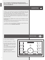
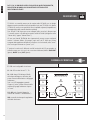
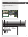
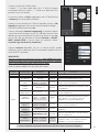
DESCRIPTION
FRONT PANEL
T1 - T8: software congurable keys.
L1 - L8: LEDs matched to T1 – T8 keys.
L9 - L16: LED bar indicating the volume
level of the selected input, output, matrix
node or group.
All its LEDs blink when the selected input,
output, matrix node or group is muted.
U1 and U2: service keys (read the
‘Operation’ manual section).
VOL: wheel to adjust the selected level.
L 9 10 11 12 13 14 15 16
L1
T1 T5
T2 T6
T3 T7
T4
U1 U2
T8
L5
L2
TS 9918
L6
L3 L7
L4 L8
VOL

7
ENGLISH
REM-CTRL
GND
24VDC
0.2A
GND
LOCK
RS 485 A
VCC
P N V
RS 485 B
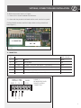
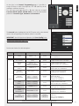
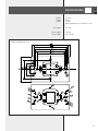
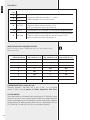
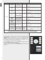
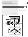
SETTINGS, CONNECTION AND INSTALLATION
TS 9918 remote control consists of 2 parts:
1. A frame to t to several standard electrical boxes.
2. A frame with the printed circuit board and the touch-sensitive front panel.
Find both the J1 connector and the six dip-switches on the printed circuit
board (gure 1).
J1 CONNECTOR
FIGURE 1
J1 CONNECTOR
DIP - SW
PIN WIRE COLOUR
1 GND Ground black
2 VCC 24 V dc input red
3 RS 485A RS 485A – serial port (half-duplex, 115200 baud) green
4 RS 485B RS 485B – serial port (half-duplex, 115200 baud) yellow
5 LOCK Link to ground (GND, pin 1) to enable the remote control blue
6 TXD1 Not connected (for programming only) white
FIGURE 2:
MZ 8060 REAR PANEL
REMOTE CONTROL
CONNECTION

8
ENGLISH
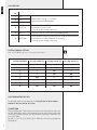
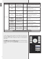
DIP-SWITCHES
DIGITAL ADDRESS SETTING
Note: each tS 9918 Shall be Set to aN uNique digital addreSS.
LINE TERMINATION (RS 485)
Set both dip-switches no.4 and no.6 to ON only if the TS 9918 remote
control is the last device of its line.
CONNECTION
Before installing the TS 9918 remote control into the electrical box, make sure
the MZ 8060 audio matrix is disconnected from the mains, then connect the
rst 5 pins of the J1 connector (on the printed circuit board) to the REM-CTRL
port of MZ 8060:
ground (1), 24 V dc (2), RS 485A (3), RS 485B (4), LOCK (5) to ground (see
the gure 2).
sw
1 ID a
Digital address setting: 1 ÷ 8 (3 bits).
Read the next manual paragraph.
2 ID b
3 ID c
4 LAST DEV
Set to ON only if the TS 9918 remote control is the last device of its
bus (otherwise, set it to OFF).
It must be set like the dip-switch no.6 .
5 BOOT 0 To be set to OFF (it is set to ON for programming only).
6 485 TERM
Line termination: to be set to ON only if the TS 9918 remote control is
the last device of its bus (otherwise, set it to OFF).
It must be set like the dip-switch no.4 .
DIGITAL ADDRESS ID c dip-switch (3) ID b dip-switch (2) ID a dip-switch (1)
1 off off off
2 off off ON
3 off ON off
4 off ON ON
5 ON off off
6 ON off ON
7 ON ON off
8 ON ON ON

9
ENGLISH
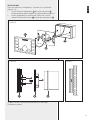
INSTALLATION
After connecting the remote control, proceed with its installation
(figures 3 and 4):
1. Fix the frame / adapter
B
to the electrical box
A
(through suitable screws).
See the frame dimensions at page 15.
2. Insert (pushing it until it clicks into) the frame with the printed
circuit board and the front panel
C
to the frame / adapter
B
.
FIGURE 3
FIGURE 4 FIGURE 5
T
he gure 5 shows the section view of the TS 9918 remote control after its
wall mounting.
A
B
C
ABC

10
ENGLISH
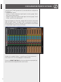
SOFTWARE CONFIGURATION
TS 9918 remote controls allow to (according to their software conguration):
- Recall presets
- Mute / unmute single inputs, single outputs, mute groups, matrix nodes
- Real-time adjust the level of single inputs, single outputs, control groups,
matrix nodes.
After linking all devices, connect both master and slave (if present) MZ 8060
audio matrices to the mains. Then run the RdNet software for PC (refer to MZ
8060 user manual about how to run the RdNet software and open the MZ
8060 window).
When in ‘Online’ mode, TS 9918 remote controls cannot be used and all
their LEDs are blinking simultaneously.
Click REMOTE CONTROLS (on the left on the main window) to open their
respective window.
On the left, there is the list of detected TS 9918.
The ‘√’ symbol (on green background) indicates that TS 9918 has been
properly connected (while the ‘–’ symbol on red background indicates ‘not
detected’ / ‘not present’).
If necessary, click either Add to add another TS 9918 remote control to the list
or Remove to remove the selected one.
When a new rmware (for TS 9918) is available, click FW Upgrade to upgrade
all the connected TS 9918.
File extension is .rdu .

11
ENGLISH
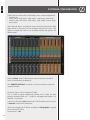
On the right, in the Controls Programming page, it is possible to
assign a function to each of the eight keys T1 – T8 (each key can be
matched to a different function).
First click one of the eight keys T1 – T8, then select the assigned
Function (PRESET, MUTE, ASSIGN LEVEL or none) and the required
parameters: Controller Type, Parameter A, Parameter B.
The Inverted option (enabled with the MUTE function only), when checked,
reverses the corresponding LED indication (when lit: unmuted).
IMPORTANT: after nishing the conguration, click Save Cong (in the
Settings page) to save all new settings (otherwise these will be lost after
turning the MZ 8060 audio matrix off).
See the next function list with descriptions:
Function Controller Type Parameter A Parameter B Description
PRESET (none) PRESET 1 – 16 (none)
It recalls the preset
set as ‘Parameter A’
MUTE
ALL OUTPUTS (none) (none) It toggles the mute state of all outputs
MASTER
INPUT
INPUT 1 – 8,
INPUT 1 – 8 (slave) *
(none)
It toggles the mute state of the
master unit input set as ‘Parameter A’
MASTER
OUTPUT
OUTPUT A – F (none)
It toggles the mute state of the
master output set as ‘Parameter A’
MASTER
MUTE GROUP
MUTE GROUP 1 – 16 (none)
It toggles the state of the master
mute group set as ‘Parameter A’
MASTER
MATRIX NODE
INPUT 1 – 8 (master),
INPUT 1 – 8 (slave) *
OUTPUT
A – F
It toggles the mute state of the master
matrix node, which
input is set as ‘Parameter A’
and output as ‘Parameter B’
SLAVE
INPUT *
INPUT 1 – 8 (master),
INPUT 1 – 8 (slave) *
(none)
It toggles the mute state of the
slave unit input set as ‘Parameter A’
SLAVE
OUTPUT *
OUTPUT A – F * (none)
It toggles the mute state of the
slave output set as ‘Parameter A’
SLAVE
MUTE GROUP *
MUTE GROUP 1 – 16 * (none)
It toggles the state of the slave
mute group set as ‘Parameter A’
SLAVE
MATRIX NODE *
INPUT 1 – 8 (master),
INPUT 1 – 8 (slave) *
OUTPUT
A – F *
It toggles the mute state of the slave matrix
node, which
input is set as ‘Parameter A’
and output as ‘Parameter B’
*Options available when the ‘slave’ MZ 8060 is present only.

12
ENGLISH
Function Controller Type Parameter A Parameter B Description
ASSIGN LEVEL
MASTER
INPUT
INPUT 1 – 8,
INPUT 1 – 8 (slave) *
(none)
If the key is selected, the VOL wheel allows to
adjust the master unit level of the input set as
‘Parameter A’
MASTER
OUTPUT
OUTPUT A – F (none)
If the key is selected, the VOL wheel allows to
adjust the level of the
master output set as ‘Parameter A’
MASTER
CONTROL GROUP
CTRL GROUP 1 - 16 (none)
If the key is selected, the VOL wheel allows to
adjust the level of the
master control group set as ‘Parameter A’
MASTER
MATRIX NODE
INPUT 1 – 8 (master),
INPUT 1 – 8 (slave) *
OUTPUT
A – F
If the key is selected, the VOL wheel allows to
adjust the master matrix node level,
which input is set as ‘Parameter A’ and output
as ‘Parameter B’
SLAVE
INPUT *
INPUT 1 – 8 (master),
INPUT 1 – 8 (slave) *
(none)
If the key is selected, the VOL wheel allows to
adjust the slave unit level of the input set as
‘Parameter A’
SLAVE
OUTPUT *
OUTPUT A – F * (none)
If the key is selected, the VOL wheel allows to
adjust the level of the
slave output set as ‘Parameter A’
SLAVE
CONTROL GROUP *
CTRL GROUP 1 – 16 * (none)
If the key is selected, the VOL wheel allows to
adjust the level of the
slave control group set as ‘Parameter A’
SLAVE
MATRIX NODE *
INPUT 1 – 8 (master),
INPUT 1 – 8 (slave) *
OUTPUT
A – F *
If the key is selected, the VOL wheel allows
to adjust the slave matrix node level, which
input is set as ‘Parameter A’ and output as
‘Parameter B’
*Options available when the ‘slave’ MZ 8060 is present only.
If no T1 – T8 key has been assigned to the ASSIGN LEVEL function (in this
case only), the VOL wheel can be set to its own LEVEL function and used as
xed level control for either a single input / output or a control group or a
matrix node.
Click Wheel, then select the LEVEL function and the required parameters:
Controller Type, Parameter A, Parameter B.
All options are the same of the ASSIGN LEVEL function previously indicated
in the list.

13
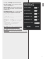
ENGLISH
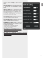
On the right, click Settings to open the respective page.
Long Press Duration: time [ms] required to consider a
‘long press’ when holding a key.
Auto-Lock Timeout: time [s] (without touching a key) after
which the TS 9918 keyboard gets automatically locked (all
LEDs blink 3 times).
Scroll Wheel Sensitivity: allows to set how many wheel
turns are required to scroll through the full level range.
Scroll Wheel Min. Level: allows to set the minimum level
[dB] adjustable by the VOL wheel.
Scroll Wheel Max. Level: allows to set the maximum level
[dB] adjustable by the VOL wheel.
LED Brightness on Locking: allows to set the LED
brightness default mode applied when the keyboard is
locked:
- DAYLIGHT: all LEDs are lit up at their maximum
- NIGHT: all LEDs are lit up at their minimum
- OFF: all LEDs are off.
Save Cong: click it to save all new settings (otherwise
these will be lost after turning the audio matrix off).
Load Cong: click it to load / recall the conguration
previously saved.
This function is useful to restore (when necessary) all remote control settings.

14
ENGLISH
KEYBOARD LOCK
The remote control keyboard gets locked (all LEDs blink three times):
- Due to an user action, by touching and holding the U1 service key (the
needed time to hold the key is set by the Long Press Duration parameter
in the Settings page).
- Automatically after a certain time (set by the Auto-Lock Timeout
parameter in the Settings page) without touching a key.
If locked, the keyboard can be unlocked by touching and holding the U1
service key.
NOTE: the keyboard can also be locked by disconnecting the J1 connector
blue wire from the ground of MZ 8060 audio matrix (in this case, the remote
control is disabled).
T1 – T8 KEYS AND VOL WHEEL
Press one of the T1 – T8 keys already set in the software (press any
uncongured key returns no effect and its LED blinks for a few seconds).
If its function is PRESET, it will recall a preset (set in the software).
If its function is MUTE, it will toggle the mute state of the selected input,
output, mute group or matrix node and the key LED will lit up when muting
(but the case the Inverted option has been previously chosen in the
software).
If its function is ASSIGN LEVEL, it will be possible to real-time adjust the level
of the selected input, output, control group or matrix node by using the VOL
wheel.
The level is indicated by the LED bar (L9 – L16). A blinking LED bar indicates
that the input, output, control group or matrix node currently controlled by
the VOL wheel is muted.
If no T1 – T8 key has been assigned to the ASSIGN LEVEL function (in this
case only), the VOL wheel can be set to its own LEVEL function and used as
xed level control for either a single input / output or a control group or a
matrix node.
OTHER WAY TO MUTE / UNMUTE
Press the U2 service key to toggle the mute state of the input, output, matrix
node or group that is currently controlled by the VOL wheel.
LED BRIGHTNESS SETTING
When using a TS 9918 remote control, all LEDs showing the current settings
are always lit up at their maximum.
Yet, it is possible to set the brightness mode that is applied only when the
remote control is not used and its keyboard is locked.
The default setting is selected via software, by the LED Brightness on
Locking parameter in the Settings page.
When the remote control keyboard is locked, press and hold the U2 service
key to change sequentially the LED brightness mode: DAYLIGHT / NIGHT /
OFF (the needed time to hold the key is set by the Long Press Duration
parameter in the Settings page).
OPERATION

15
ENGLISH
SPECIFICATIONS
Width:
Height:
Depth:
Net weight:
Power supply:
Current drain:
140 mm
90 mm
27 mm
(part protruding from the wall: 14 mm).
0.22 kg
24 V dc
20 ÷ 40 mA
FRAME DIMENSIONS [mm]

16
ITALIANO
AVVERTENZE PER
LA SICUREZZA
IMPORTANTE
IMPORTANTE
Prima di collegare ed utilizzare questo prodotto, leggere attentamente
le istruzioni contenute in questo manuale, il quale è da conservare per
riferimenti futuri.
Il presente manuale costituisce parte integrante del prodotto e deve
accompagnare quest’ultimo anche nei passaggi di proprietà, per permettere
al nuovo proprietario di conoscere le modalità d’installazione e d’utilizzo e le
avvertenze per la sicurezza.
L’installazione e l’utilizzo errati del prodotto esimono la RCF S.p.A. da ogni
responsabilità.
ATTENZIONE: Per prevenire i rischi di amme o scosse elettriche, non
esporre le parti che compongono il controllo remoto alla pioggia od
all’umidità.
AVVERTENZE PER LA SICUREZZA
1. Tutte le avvertenze, in particolare quelle relative alla sicurezza, devono
essere lette con particolare attenzione, in quanto contengono importanti
informazioni.
2. Assicurarsi che il sistema audio sia spento prima di collegare il controllo
remoto TS 9918.
3. Assicurarsi che tutte le connessioni siano corrette.
4. Impedire che oggetti o liquidi entrino nel prodotto, perché potrebbero
causare un corto circuito.
5. Non eseguire sul prodotto interventi / modiche / riparazioni.
Contattare i centri di assistenza autorizzati o personale altamente qualicato
quando:
- il controllo remoto non funziona (o funziona in modo anomalo);
- oggetti o liquidi sono entrati nel controllo remoto;
- il controllo remoto non è più integro (a causa di urti / incendio).
6. Nel caso che dalle parti che compongono il controllo remoto provengano
odori anomali o fumo, scollegarlo dopo aver immediatamente spento il
sistema.
7. Non collegare al controllo remoto apparecchi ed accessori non previsti.
Vericare l’idoneità del supporto (parete, struttura, ecc.) e dei componenti
utilizzati per il ssaggio che devono garantire la sicurezza dell’impianto
/ installazione nel tempo, anche considerando, ad esempio, vibrazioni
meccaniche normalmente generate da altoparlanti.

17
ITALIANO
8. La RCF S.p.A. raccomanda vivamente che l’installazione di questo
prodotto sia eseguita solamente da installatori professionali qualicati
(oppure da ditte specializzate) in grado di farla correttamente e certicarla
in accordo con le normative vigenti. Tutto il sistema audio dovrà essere in
conformità con le norme e le leggi vigenti in materia di impianti elettrici.
9. Perdita dell’udito
L’esposizione ad elevati livelli sonori può provocare la perdita permanente
dell’udito. Il livello di pressione acustica pericolosa per l’udito varia
sensibilmente da persona a persona e dipende dalla durata dell’esposizione.
Per evitare un’esposizione potenzialmente pericolosa ad elevati livelli di
pressione acustica, è necessario che chiunque sia sottoposto a tali livelli
utilizzi delle adeguate protezioni; quando si fa funzionare un trasduttore in
grado di produrre elevati livelli sonori è necessario indossare dei tappi per
orecchie o delle cufe protettive.
10. Per evitare che fenomeni induttivi diano luogo a ronzii, disturbi e
compromettano il buon funzionamento dell’impianto, il cavo del controllo
remoto non dovrebbe essere posto vicino a campi elettromagnetici e
canalizzato insieme ai conduttori dell’energia elettrica, ai cavi microfonici,
alle linee di segnale e quelle dei diffusori acustici che fanno capo ad
amplicatori.
11. Collocare il controllo remoto lontano da fonti di calore.
12. Non usare solventi, alcool, benzina o altre sostanze volatili per la pulitura
delle parti esterne; utilizzare un panno asciutto.
AVVERTENZE PER
LA SICUREZZA

18
ITALIANO
RCF S.P.A. VI RINGRAZIA PER L’ACQUISTO DI QUESTO PRODOTTO,
REALIZZATO IN MODO DA GARANTIRNE L’AFFIDABILITÀ E
PRESTAZIONI ELEVATE.
DESCRIZIONE
TS 9918 è un controllo remoto per la matrice audio MZ 8060, con un design
elegante e tastiera sensibile al tocco, disponibile sia in nero (TS 9918) sia in bianco
(TS 9918-W), sottile e con supercie di vetro, installabile a parete (compatibile con
la maggior parte delle scatole elettriche standard).
Fino ad otto TS 9918 possono essere collegati (nello stesso bus) alla porta per
il controllo remoto solo della prima matrice audio MZ 8060 (congurata come
“Master Only” oppure “Master+Slave”).
Gli otto tasti laterali T1-T8 (ed altre impostazioni) possono essere congurati
tramite il software RdNet. Ad esempio, ogni tasto del TS 9918 può essere
assegnato alla regolazione del livello di un ingresso / un’uscita audio, come “mute”
di un’uscita, per richiamare un “preset”, ecc. .
E’ prevista la scelta tra 3 differenti modi di luminosità dei LED per quando un
controllo remoto non è in uso (e la sua tastiera è bloccata) deniti: DAYLIGHT
(giorno), NIGHT (notte), OFF (spento).
PANNELLO FRONTALE
T1 - T8: tasti congurabili via software.
L1 - L8: LED associati ai tasti T1 - T8.
L9 - L16: barra LED indicante il livello
del volume dell’ingresso, dell’uscita, del
punto d’incrocio della matrice o del gruppo
selezionato.
Tutti i suoi LED lampeggiano quando
l’ingresso, l’uscita, il punto d’incrocio della
matrice od il gruppo selezionato è posto
in “mute”.
U1 e U2: tasti di servizio (leggere la
sezione del manuale “Funzionamento”).
VOL: controllo circolare per la regolazione
del livello selezionato.
L 9 10 11 12 13 14 15 16
L1
T1 T5
T2 T6
T3 T7
T4
U1 U2
T8
L5
L2
TS 9918
L6
L3 L7
L4 L8
VOL

19
ITALIANO
REM-CTRL
GND
24VDC
0.2A
GND
LOCK
RS 485 A
VCC
P N V
RS 485 B
PIN COLORE CONDUTTORE
1 GND Contatto di massa nero
2 VCC Ingresso alimentazione 24 V c.c. rosso
3 RS 485A Porta seriale RS 485A (half-duplex, 115200 baud) verde
4 RS 485B Porta seriale RS 485B (half-duplex, 115200 baud) giallo
5 LOCK Collegare a massa (GND, pin 1) per abilitare il controllo remoto blu
6 TXD1 Non collegare (da usarsi solo per la programmazione) bianco
IMPOSTAZIONI, COLLEGAMENTO ED INSTALLAZIONE
Un controllo remoto TS 9918 si compone di 2 parti:
1. un telaio per l'adattamento alla maggior parte delle scatole elettriche
standard;
2. un telaio con il circuito stampato ed il pannello frontale sensibile al tocco.
Individuare sul circuito stampato il connettore J1 ed i sei microinterruttori
DIP-SWITCH (gura 1).
CONNETTORE J1
FIGURA 1
CONNETTORE J1
DIP - SW
FIGURA 2:
COLLEGAMENTO
CONTROLLO REMOTO
AL RETRO DELL'MZ 8060

20
ITALIANO
Indirizzo digitale Dip-switch ID c (3) Dip-switch ID b (2) Dip-switch ID a (1)
1 off off off
2 off off ON
3 off ON off
4 off ON ON
5 ON off off
6 ON off ON
7 ON ON off
8 ON ON ON
DIP-SWITCH
sw
1 ID a
Impostazione dell’indirizzo digitale (1 ÷ 8, 3 bit).
Vedere il paragrafo successivo del manuale.
2 ID b
3 ID c
4 LAST DEV
Impostare su ON solo se il controllo remoto TS 9918 è l’ultimo
dispositivo del bus, altrimenti lasciarlo su OFF;
deve essere impostato come il dip-switch nr.6 .
5 BOOT 0 Da mantenere su OFF (si imposta su ON solo per la ri-programmazione).
6 485 TERM
Terminazione della linea: da impostare su ON solo se il controllo remoto
TS 9918 è l’ultimo dispositivo del bus, altrimenti lasciarlo su OFF;
deve essere impostato come il dip-switch nr.4 .
IMPOSTAZIONE DELL'INDIRIZZO DIGITALE
Nota: ogNi coNtrollo remoto tS 9918 deve avere uN Suo uNico iNdirizzo digitale
(diverSo dagli altri).
TERMINAZIONE DELLA LINEA (RS 485)
Impostare entrambi i dip-switch nr.4 e nr.6 su ON su un controllo
remoto TS 9918 (solo) se questo è l'ultimo dispositivo della linea.
COLLEGAMENTO
Prima di procedere con l’installazione del controllo remoto TS 9918 nella scatola
da incasso, assicurarsi che la matrice audio MZ 8060 sia scollegata dalla rete
elettrica, poi collegare i primi 5 contatti del connettore J1 (del circuito stampato)
alla porta REM-CTRL della matrice MZ 8060: massa (1), alimentazione 24 V c.c.
(2), RS 485A (3), RS 485B (4), LOCK (5) a massa (vedere la gura 2).
La pagina si sta caricando...
La pagina si sta caricando...
La pagina si sta caricando...
La pagina si sta caricando...
La pagina si sta caricando...
La pagina si sta caricando...
La pagina si sta caricando...
La pagina si sta caricando...
-
 1
1
-
 2
2
-
 3
3
-
 4
4
-
 5
5
-
 6
6
-
 7
7
-
 8
8
-
 9
9
-
 10
10
-
 11
11
-
 12
12
-
 13
13
-
 14
14
-
 15
15
-
 16
16
-
 17
17
-
 18
18
-
 19
19
-
 20
20
-
 21
21
-
 22
22
-
 23
23
-
 24
24
-
 25
25
-
 26
26
-
 27
27
-
 28
28


RCF TS 9918-W Manuale utente
- Tipo
- Manuale utente
- Questo manuale è adatto anche per
in altre lingue
- English: RCF TS 9918-W User manual
Altri documenti
-
Yamaha V3 Manuale del proprietario
-
Yamaha V4.0 Manuale del proprietario
-
-
-
-
-
-
-
Yamaha CL3 Manuale utente
-
Yamaha QL5 Manuale utente