IBT Technologies IB881 Manuale utente
- Categoria
- Schede madri
- Tipo
- Manuale utente


ii
IB881 User’s Manual
Acknowledgments
Award is a registered trademark of Award Software International, Inc.
PS/2 is a trademark of International Business Machines Corporation.
Intel and Pentium M are registered trademarks of Intel Corporation.
Microsoft Windows is a registered trademark of Microsoft Corporation.
Winbond is a registered trademark of Winbond Electronics Corporation.
All other product names or trademarks are properties of their respective
owners.

IB881 User’s Manual iii
Table of Contents
Introduction.......................................................1
Product Description.............................................................1
Checklist..............................................................................2
IB881 Specifications...........................................................3
Board Dimensions...............................................................4
Installations.......................................................5
Installing the CPU...............................................................6
Installing the Memory.........................................................7
Setting the Jumpers .............................................................8
Connectors on IB881.........................................................11
BIOS Setup.......................................................21
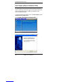
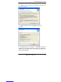
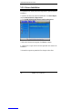
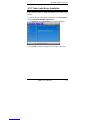
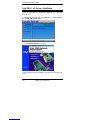
Drivers Installation......................................45
Intel Chipset Software Intallation Utility..........................46
VGA Drivers Installation ..................................................48
AC97 Codec Audio Driver Installation.............................49
Intel PRO LAN Drivers Installation..................................50
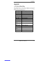
Appendix...........................................................51
A. I/O Port Address Map...................................................51
B. Interrupt Request Lines (IRQ)......................................52
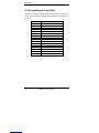
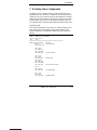
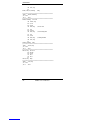
C. Watchdog Timer Configuration....................................53
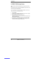
D. IB881 CMOS Backup Feature .....................................56


INTRODUCTION
IB881 User’s Manual 1
Introduction
Product Description
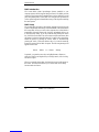
The IB881 3.5-inch disk size SBC incorporates the Intel® advanced
855GME/852GM Chipset that contains two core components: the Memory
Controller Hub (GMCH) and ICH4. The GMCH integrates a 400MHz Pentium®
M processor front side bus controller, integrated graphics controller hub,
integrated LVDS interface, two digital video out ports multiplexed with an AGP
4x controller, a 200/266/ 333MHz DDR-SDRAM controller, and a high-speed
accelerated hub architecture interface for communication with the ICH4.
The ICH4 integrates an Ultra ATA 100/66/33 controller, USB host controller
that supports the USB 1.1 and USB 2.0 specification, LPC interface, FWH Flash
BIOS interface controller, AC’97 digital controller and a hub interface for
communication with the GMCH.
The Pentium M processor is a higher performance, lower power processor with
several microarchitectural enhancements over existing Intel low-power
processors. Some key features of the Pentium M processor microarchitecture
include dynamic execution, data pre-fetch logic, 400MHz source-synchronous
Front Side Bus (FSB), on-die 1 Mbyte second level cache (on-die 512Kbyte
second level cache on Celeron M processor) with advanced transfer cache
architecture, streaming SIMD extensions 2 (SSE2), and Enhanced Intel
SpeedStep technology.
IB881 FEATURES:
- Intel® 82855GME/82852GM chipset
- Supports Intel® Pentium® M, Celeron® M
- SO-DIMM socket supports up to 1GB DDR SDRAM
- 10/100 BaseT Ethernet with RJ45 connector
- 24-bit LVDS, VGA CRT support
- USB x4, RS232 COM x2, PS/2 Mouse/Keyboard
- IDE x2, FDD, LPT, 12V power connector, PC/104+
- 102.24mm x 148.03mm

INTRODUCTION
2
IB881 User’s Manual
Checklist
Your IB881 package should include the items listed below.
• The IB881 Pentium® M 3.5-inch Disk Size SBC
• This User’s Manual
• 1 CD containing chipset drivers and flash memory utility
• Options:
• IB32 - Cable kit with IDE, COM, Printer, Audio, USB, PS/2 Y cable
• IB33 - Kit with ATX power switch, power cable
• IB881SW-R - ATX power switch board for IB881
• IB881PW-R - ATX power board for IB881
• ICOOL010-P – Heatsink for IB881 (Socket 478)

INTRODUCTION
IB881 User’s Manual 3
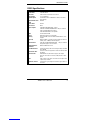
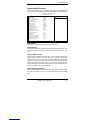
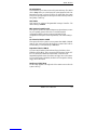
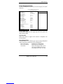
IB881 Specifications
[
Product Name IB881
Form Factor 3 1/2 little board
Processor Intel Pentium M /Celeron M Processor
CPU Voltage 0.7~1.7V(IMVP4)
System Speed Pentium M/Celeron M 900MHz-1.7GHz (Low-Power,
Low-voltage)
CPU External Clock
/ FSB 400MHz
Green /APM APM1.2
CPU Socket None
Major Chipset Intel 82855GME/82852GM chipset
Intel GMCH 82855GME/82852GM 732-pin uFCBGA
Intel ICH4 82801DB 421-pin BGA
Intel FWH 82802ABA or compatible
BIOS Phoenix/Award ROM
Cache 256K/1M Level2 (CPU integrated)
Memory One SO-DIMM socket for DDR SDRAM Module; 2.5V
Support
Super I/O Winbond 83627 1 Parallel (LPT1)*1 Serial*2 (COM1 &
COM2); FDC 2.88MB (3 Mode Support)
Onboard VGA Intel GMCH 82855GME/82852GM 732-pin uFCBGA
integrated support CRT and LVDS ;
Keyboard/Mouse
Controller Winbond 83627HF built-in
Dual IDE Channel Primary/Secondary IDE Channel support 44pin for HDD
and CDROM
Onboard PC104+ PC104+ connector support four master PCI Bus/ 32 Bits
@ 33MHz
Onboard LAN Intel 82562ET 10 /100 BaseT support, full duplex
1xRJ-45 connector and 2x LED (LINK /Active on front
panel
USB Total 4 ports 2 USB ports connector for front panel and
2 ports for pin header
Keyboard / Mouse Combo PS/2 Type (Keyboard & Mouse) signal both on
connector


INSTALLATIONS
IB881 User’s Manual 5
Installations
This section provides information on how to use the jumpers and
connectors on the IB881 in order to set up a workable system. The topics
covered are:
Installing the CPU........................................................................ 6
Installing the Memory.................................................................. 7
Setting the Jumpers...................................................................... 8
Connectors on IB881 ................................................................. 11

INSTALLATIONS
6
IB881 User’s Manual
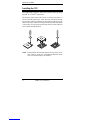
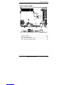
Installing the CPU
The IB881 board supports a Socket 479 processor socket for Intel®
Pentium® M or Celeron® M processors.
The processor socket comes with a screw to secure the processor. As
shown in the left picture below, loosen the screw first before inserting
the processor. Place the processor into the socket by making sure the
notch on the corner of the CPU corresponds with the notch on the inside
of the socket. Once the processor has slide into the socket, fasten the
screw. Refer to the figures below.
NOTE: Ensure that the CPU heat sink and the CPU top surface are in
total contact to avoid CPU overheating problem that would
cause your system to hang or be unstable.

INSTALLATIONS
IB881 User’s Manual 7
Installing the Memory
The IB881 board supports one SODIMM DDR memory socket for a
maximum total memory. The memory module capacities supported are
128MB, 256MB, 512MB and 1GB.
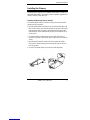
Installing and Removing Memory Modules
To install the DDR modules, locate the memory slot on the board and
perform the following steps:
1. Hold the DDR module so that the key of the DDR module align with
those on the memory slot. Insert the module into the socket at a slight
angle (approximately 30 degrees). Note that the socket and module
are both keyed, which means that the module can be installed only in
one direction.
2. To seat the memory module into the socket, apply firm and even
pressure to each end of the module until you feel it slip down into the
socket.
3. With the module properly seated in the socket, rotate the module
downward. Continue pressing downward until the clips at each end
lock into position.
4. To remove the DDR module, press the clips with both hands.

INSTALLATIONS
8
IB881 User’s Manual
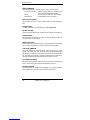
Setting the Jumpers
Jumpers are used on IB881 to select various settings and features
according to your needs and applications. Contact your supplier if you
have doubts about the best configuration for your needs. The following
lists the connectors on IB881 and their respective functions.
Jumper Locations on IB881............................................................9
JP2: Clear CMOS Setting.............................................................10
JP6: LVDS VDD Select (5V / 3.3V)............................................10
JP8: AT/ATX Power Mode Setting..............................................10

INSTALLATIONS
IB881 User’s Manual 9
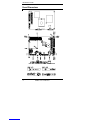
Jumper Locations on IB881
Jumpers on IB881......................................................................Page
JP2: Clear CMOS Setting............................................................. 10
JP6: LVDS VDD Select (5V / 3.3V)............................................ 10
JP8: AT/ATX Power Mode Setting.............................................. 10

INSTALLATIONS
10
IB881 User’s Manual
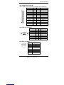
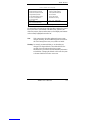
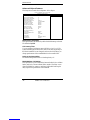
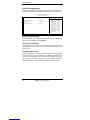
JP2: Clear CMOS Setting
Use JP2 to clear the CMOS contents. Note that the power connector
should be disconnected from the board before clearing CMOS.
JP2 Function
Normal (default)
Clear CMOS
JP6: LVDS VDD Select (5V / 3.3V)
JP6 VDD Setting
3.3V
5V
[
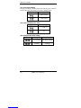
JP8: AT/ATX Power Mode Setting
JP8 Setting Power Mode
1-2, 3-4 Short ATX Mode (default)
2-3 Short AT Mode

INSTALLATIONS
IB881 User’s Manual 11
Connectors on IB881
The connectors on IB881 allows you to connect external devices such as
keyboard, floppy disk drives, hard disk drives, printers, etc. The
following table lists the connectors on IB881 and their respective
functions.
Connector Locations on IB881..................................................... 12
CN1: Floppy Drive Connector ..................................................... 13
CN2: VGA CRT Connector ......................................................... 13
CN3:RJ45 Connector ................................................................... 13
CN4: PS/2 Keyboard and Mouse Connector................................ 14
CN5, J6: USB Connectors............................................................ 14
CN6, J11: Serial Ports.................................................................. 14
CN7: PC104+ Connector.............................................................. 15
PC/104-Plus Bus Signal Assignments.......................................... 15
J2, J3: IDE Connectors................................................................. 16
J8: Parallel Port Connector........................................................... 17
J9: IrDA Connector...................................................................... 17
J12: External Audio Connector.................................................... 17
J13, J24: LVDS Connectors (1st channel, 2nd channel).............. 18
J21: Function Connector .............................................................. 18
J23: Power DC-In......................................................................... 19
J27: Buzzer Connector ................................................................. 19

INSTALLATIONS
12
IB881 User’s Manual
Connector Locations on IB881
Connectors on IB881................................................................ Page
CN1: Floppy Drive Connector......................................................13
CN2: VGA CRT Connector..........................................................13
CN3: RJ45 Connector...................................................................13
CN4: PS/2 Keyboard and Mouse Connector................................14
CN5, J6: USB Connectors............................................................14
CN6, J11: Serial Ports...................................................................14
CN7: PC104+ Connector..............................................................15
PC/104-Plus Bus Signal Assignments..........................................15
J2, J3: IDE Connectors.................................................................16
J8: Parallel Port Connector...........................................................17
J9: IrDA Connector ......................................................................17
J12: External Audio Connector ....................................................17
J13, J24: LVDS Connectors (1st channel, 2nd channel) ..............18
J21: Function Connector...............................................................18
J23: Power DC-In.........................................................................19
J27: Buzzer Connector..................................................................19

INSTALLATIONS
IB881 User’s Manual 13
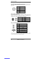
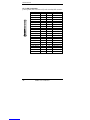
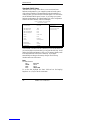
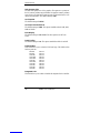
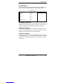
CN1: Floppy Drive Connector
CN1 is a slim 26-pin connector and will support up to 2.88MB FDD.
Signal Name Pin # Pin # Signal Name
VCC 1 2 INDEX
VCC 3 4 DRV_SEL
VCC 5 6 DSK_CH
NC 7 8 NC
NC 9 10 MOTOR
DINST 11 12 DIR
NC 13 14 STEP
GND 15 16 WDATA
GND 17 18 WGATE
GND 19 20 TRACK
NC 21 22 WPROT
GND 23 24 RDATA
GND 25 26 SIDE
CN2: VGA CRT Connector
[ Signal Name Pin Pin Signal Name
Red 1 2 Green
Blue 3 4 NC
GND 5 6 GND
GND 7 8 GND
Vcc 9 10 GND
N.C. 11 12 DDCDA
HSYNC 13 14 VSYNC
DDCCLK 15
CN3: RJ45 Connector
Pin # Signal Name
1 TD+
2 TD-
3 RD+
4 RJ45-4A
5 RJ45-5A
6 RD-
7 RJ45-7A
8 RJ45-8A

INSTALLATIONS
14
IB881 User’s Manual
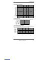
CN4: PS/2 Keyboard and Mouse Connector
CN4 uses a Y-cable with dual D-connectors for a PS/2 keyboard and a
PS/2 mouse.
Pin # Signal Name
1 Mouse data
2 Keyboard data
3 Ground
4 Vcc
5 Mouse Clock
6 Keyboard Clock
CN5, J6: USB Connectors
The J6 USB pin header connector supports two USB 2.0 ports via an
optional USB cable. The IB881 also supports an embedded USB
connector, CN5, which supports another two USB ports.
Signal Name Pin Pin Signal Name
Vcc 1 5 Ground
USB0- 2 6 USB1+
USB0+ 3 7 USB1-
Port1
Port2
CN5
J6 Ground 4 8 Vcc
CN6, J11: Serial Ports
Pin # Signal Name (RS-232)
1 DCD, Data carrier detect
2 RXD, Receive data
3 TXD, Transmit data
4 DTR, Data terminal ready
5 Ground
6 DSR, Data set ready
7 RTS, Request to send
8 CTS, Clear to send
9 RI, Ring indicator
10 No Connect.
CN6 is the D-sub type COM1 serial port connector, while J11 (COM2)
is a pin header type COM2 serial port connector.

INSTALLATIONS
IB881 User’s Manual 15
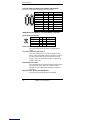
CN7: PC104+ Connector
PC/104-Plus Bus Signal Assignments
J3/P3
Pin A B C D
1 GND/5.0V KEY² Reserved +5 AD00
2 VI/O AD02 AD01 +5V
3 AD05 GND AD04 AD03
4 C/BE0* AD07 GND AD06
5 GND AD09 AD08 GND
6 AD11 VI/O AD10 M66EN
7 AD14 AD13 GND AD12
8 +3.3V C/BE1* AD15 +3.3V
9 SERR* GND SB0* PAR
10 GND PERR* +3.3V SDONE
11 STOP* +3.3V LOCK* GND
12 +3.3V TRDY* GND DEVSEL*
13 FRAME* GND IRDY* +3.3V
14 GND AD16 +3.3V C/BE2*
15 AD18 +3.3V AD17 GND
16 AD21 AD20 GND AD19
17 +3.3V AD23 AD22 +3.3V
18 IDSEL0 GND IDSEL1 IDSEL2
19 AD24 C/BE3* VI/O IDSEL3
20 GND AD26 AD25 GND
21 AD29 +5V AD28 AD27
22 +5V AD30 GND AD31
23 REQ0* GND REQ1* VI/O
24 GND REQ2* +5V GNT0*
25 GNT1* VI/O GNT2* GND
26 +5V CLK0 GND CLK1
27 CLK2 +5V CLK3 GND
28 GND INTD* +5V RST*
29 +12V INTA* INTB* INTC*
30 -12V Reserved Reserved GND/3.3V
KEY²
* The shaded area denotes power or ground signals.
* The KEY pins are to guarantee proper module installation. Pin-A1 will
be removed and the female side plugged for 5.0V I/O signals and
Pin-D30 will be modified in the same manner for 3.3V I/O. It is
recommended that both KEY pins (A1 and D30) be electrically
connnected for GND for shielding.

BIOS SETUP
16
IB881 User’s Manual
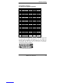
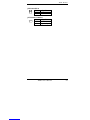
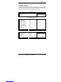
J2, J3: IDE Connectors
J2 is the primary IDE connector and J3 is the secondary IDE connector.
Signal Name Pin # Pin # Signal Name
Reset IDE 1 2 Ground
Host data 7 3 4 Host data 8
Host data 6 5 6 Host data 9
Host data 5 7 8 Host data 10
Host data 4 9 10 Host data 11
Host data 3 11 12 Host data 12
Host data 2 13 14 Host data 13
Host data 1 15 16 Host data 14
Host data 0 17 18 Host data 15
Ground 19 20 Key
DRQ0 21 22 Ground
Host IOW 23 24 Ground
Host IOR 25 26 Ground
IOCHRDY 27 28 Host ALE
DACK0 29 30 Ground
IRQ14 31 32 No connect
Address 1 33 34 No connect
Address 0 35 36 Address 2
Chip select 0 37 38 Chip select 1
Activity 39 40 Ground
Vcc 41 42 Vcc
Ground 43 44 N.C.
La pagina sta caricando ...
La pagina sta caricando ...
La pagina sta caricando ...
La pagina sta caricando ...
La pagina sta caricando ...
La pagina sta caricando ...
La pagina sta caricando ...
La pagina sta caricando ...
La pagina sta caricando ...
La pagina sta caricando ...
La pagina sta caricando ...
La pagina sta caricando ...
La pagina sta caricando ...
La pagina sta caricando ...
La pagina sta caricando ...
La pagina sta caricando ...
La pagina sta caricando ...
La pagina sta caricando ...
La pagina sta caricando ...
La pagina sta caricando ...
La pagina sta caricando ...
La pagina sta caricando ...
La pagina sta caricando ...
La pagina sta caricando ...
La pagina sta caricando ...
La pagina sta caricando ...
La pagina sta caricando ...
La pagina sta caricando ...
La pagina sta caricando ...
La pagina sta caricando ...
La pagina sta caricando ...
La pagina sta caricando ...
La pagina sta caricando ...
La pagina sta caricando ...
La pagina sta caricando ...
La pagina sta caricando ...
La pagina sta caricando ...
La pagina sta caricando ...
La pagina sta caricando ...
La pagina sta caricando ...
-
 1
1
-
 2
2
-
 3
3
-
 4
4
-
 5
5
-
 6
6
-
 7
7
-
 8
8
-
 9
9
-
 10
10
-
 11
11
-
 12
12
-
 13
13
-
 14
14
-
 15
15
-
 16
16
-
 17
17
-
 18
18
-
 19
19
-
 20
20
-
 21
21
-
 22
22
-
 23
23
-
 24
24
-
 25
25
-
 26
26
-
 27
27
-
 28
28
-
 29
29
-
 30
30
-
 31
31
-
 32
32
-
 33
33
-
 34
34
-
 35
35
-
 36
36
-
 37
37
-
 38
38
-
 39
39
-
 40
40
-
 41
41
-
 42
42
-
 43
43
-
 44
44
-
 45
45
-
 46
46
-
 47
47
-
 48
48
-
 49
49
-
 50
50
-
 51
51
-
 52
52
-
 53
53
-
 54
54
-
 55
55
-
 56
56
-
 57
57
-
 58
58
-
 59
59
-
 60
60


IBT Technologies IB881 Manuale utente
- Categoria
- Schede madri
- Tipo
- Manuale utente
in altre lingue
- English: IBT Technologies IB881 User manual