STEINEL IR Quattro SLIM XS 4m DALI-2 Input Device Manuale utente
- Categoria
- Rilevatori di movimento
- Tipo
- Manuale utente

- 3 -
STEINEL Vertrieb GmbH
Dieselstraße 80-84
33442 Herzebrock-Clarholz
Tel: +49/5245/448-188
www.steinel.de
Contact
www.steinel.de/contact
110072619 09/2019_A Technische Änderungen vorbehalten. / Subject to technical modification without notice.
000000000 07/2013 Technische Änderungen vorbehalten.
RUS CN BG LV LT EST HR SLO RO PL SK CZ H TR GR N FIN DK S P E I NL F GB D
STL-7384-16_IR QUATTRO SLIM XS_BDAL_A6.indd 1 02.03.17 15:20
IR Quattro SLIM XS
DALI-2 Input device
Information
LV
RU
BG LT EE HR SI RO PL SK CZ HU TR GR NO FI DK SE PT ES IT NL FR GB DECN

- 2 - - 3 -
...
Textteil beachten!
Follow written instructions!
Se référer à la partie texte !
Neem de tekst in acht
Seguire attentamente le istruzioni!
¡Téngase en cuenta el texto!
Siga as instruções escritas!
Iaktta texten!
Følg den skriftlige vejledning!
Huomaa tekstiosio!
Se de skriftlige instruksene!
Τηρείτε γραπτές οδηγίες!
Metin kısmını dikkate alın!
Szöveges részre figyelni!
Dodržujte informace v textové části!
Dodržiavajte informácie v textovej časti!
Postępować zgodnie z instrukcją!
Respectaţi instrucţiunile scrise!
Upoštevajte del besedila!
Pridržavajte se pisanih uputa!
Järgige kirjalikke juhiseid!
Laikykitės rašytinių instrukcijų!
Pievērsiet uzmanību tekstam!
Обратите внимание на текстовую часть!
Да се вземе предвид текстовата част!
注意正文!
– 3 –
3.1
3.2
80
45
80
51
Ø 94
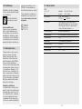
DE . . . . . . . 11
GB . . . . . . . 16
FR . . . . . . .21
NL . . . . . . .26
IT . . . . . . . . 31
ES . . . . . . . . 36
PT . . . . . . . . 41
SE . . . . . . . . 46
DK . . . . . . . 51
FI . . . . . . . . 56
NO . . . . . . . 61
GR . . . . . . . 66
TR . . . . . . .71
HU . . . . . . . 76
CZ . . . . . . . 81
SK . . . . . . . 86
PL . . . . . . . . 91
RO . . . . . . .96
SI . . . . . . . 101
HR . . . . . . 106
EE . . . . . . . 111
LT . . . . . . .116
LV . . . . . . .121
RU . . . . . . 126
BG . . . . . . 131
CN . . . . . . 136

- 4 - - 5 -
– 4 –
3�3 4
C
A
B
D
DA+ DA
-
4�1
L N DA
DA
DA
DA
DA
L
N
L
N
S
DA
DA
LiveLink
BOX
EVG
LED
DA+ DA-
+
-+
-
DA+ DA-
I
O
5
– 5 –
5.1
< 6 m
2,8 m

- 6 - - 7 -
– 6 –
5.2
~ 4 m
~ 4 m
5.3
– 7 –
5�4
57
ø 68
5�5
DA+ DA
-
DA+ DA-

- 8 - - 9 -
– 8 –
5�6
6
– 9 –
6�1
75%60%

- 10 - - 11 -
...
– 10 –
6�2
100%
75%
60%
6�3
I
O
DE
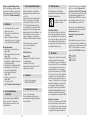
1. Zu diesem Dokument
Bitte sorgfältig lesen und
aufbewahren!
– Urheberrechtlich geschützt. Nach-
druck, auch auszugsweise, nur
mit unserer Genehmigung.
– Änderungen, die dem technischen
Fortschritt dienen, vorbehalten.
Symbolerklärung
Warnung vor Gefahren!
Verweis auf Textstellen im
Dokument.
2. Allgemeine
Sicherheitshinweise
!
Vor allen Arbeiten am Gerät
die Spannungszufuhr
unterbrechen!
• Bei der Montage muss die anzu-
schließende elektrische Leitung
spannungsfrei sein. Daher als
Erstes Strom abschalten und
Spannungsfreiheit mit einem
Spannungsprüfer überprüfen.
• Bei der Installation des Sensors
handelt es sich um eine Arbeit an
der Netzspannung. Sie muss daher
fachgerecht nach den landesübli-
chen Installationsvorschriften und
Anschlussbedingungen durchge-
führt werden. (z. B.: DE: VDE 0100,
AT: OVE-EN 1, CH: SEV 1000).
• Nur Original-Ersatzteile verwenden.
• Reparaturen dürfen nur durch
Fachwerkstätten durchgeführt
werden.
3. IR Quattro SLIM XS
Bestimmungsgemäßer Gebrauch
– Präsenzmelder nur zur Decken-
montage im Innenbereich
geeignet.
– Gerätedose mit min. 57mm Tiefe
erforderlich.
Mit einem DALI-Bus wird der Sensor
an das Steuergerät angebunden.
Der Sensor nutzt die DALI-Leitung zur
Kommunikation und zur Spannungs-
versorgung.
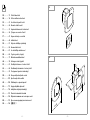
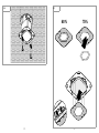
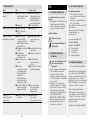
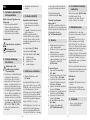
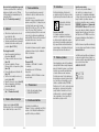
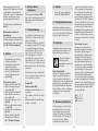
Lieferumfang (Abb.3.1)
Produktmaße (Abb.3.2)
Geräteübersicht (Abb.3.3)
A Sensormodul
B Designblende
C Sensorlinse
D Anschlussklemme
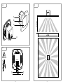
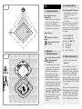
4. Elektrischer Anschluss
• Stromversorgung abschalten.
(Abb.4.1)
Für die Verdrahtung der Sensor-
schalter gilt: Nach VDE0100520
Abschnitt 6 darf für die Verdrahtung
zwischen Sensor und DALI App-
lication Controller eine Mehrfach-
leitung verwendet werden, die sowohl
die Netzspannungsleitungen wie auch
die Steuerleitungen enthält (z.B. NYM
5×1,5mm²).
Die maximale Leitungslänge zwischen
DALI Application Controller und Sen-
sor darf 300m (bei 1,5mm²) nicht
überschreiten. Nach der Installation
und dem Einschalten beginnt der
Sensor für 40 Sekunden zu blinken.
...
!

- 12 - - 13 -
Anschluss Netzzuleitung (Abb.4.1)
Hinweis zur Parallelschaltung:
Es können in einem DALI-2-System
mehrere Sensoren angeschlossen
werden. Hierbei ist die maximale
DALI-Teilnehmerzahl zu beachten
(➜ "12.Technische Daten")
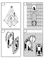
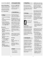
5. Montage
• Alle Bauteile auf Beschädigungen
prüfen.
• Bei Schäden das Produkt nicht in
Betrieb nehmen.
• Geeigneten Montageort aus-
wählen unter Berücksichtigung
der Reichweite und Bewegungs-
erfassung. (Abb.5.1/5.2)
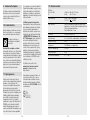
Montageschritte
• Stromversorgung abstellen.
(Abb.4.1)
• Designblende vom Rahmen lösen.
(Abb.5.3)
• Einbaudose Ø max. 68mm in
den Deckenausschnitt einsetzen.
(Abb.5.4)
• Netzanschlüsse vornehmen.
(Abb.5.5)
• Sensormodul einsetzen und
verschrauben. (Abb.5.6)
• Designblende aufstecken.
(Abb.6.3)
• Stromversorgung einschalten.
(Abb.6.3)
• Einstellungen vornehmen.
(➜ "7.Funktion/Bedienung")
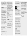
6. Erfassungsbereich ändern
Erfassungsbereich (Abb.6.1/6.2)
Die beiliegende Abdeckfolie dient
zur Minimierung des Erfassungs-
bereiches um max. 40 %.
7. Funktion/Bedienung
Nachdem der Anschluss vorge-
nommen und die Designblende
aufgesteckt ist, kann die Anlage in
Betrieb genommen werden.
Die Inbetriebnahme erfolgt gemäß der
gültigen DALI-2-Norm. Es stehen alle
Funktionen und Befehle aus der DALI-
Norm IEC 62386 Teil101, Teil103,
Teil303 und Teil304 zur Verfügung.
Die vom Sensor ermittelten Bewe-
gungs- und Helligkeitswerte können
vom DALI Application Controller
abgefragt werden. Zusätzlich besteht
die Möglichkeit eines automati-
schen oder zeitbasierten zyklischen
Sendens.
Detaillierte Informationen finden Sie
in der Schnittstellenbeschreibung im
Internet auf: DALI-2.steinel.de
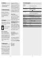
LED-Funktion:
Rote LED
Initialisierung: LED blinkt 1×alle
2Sekunden
Normalbetrieb: LED bleibt aus.
DALI-Identifikation: LED blinkt im
Sekundentakt.
8. Zubehör
– Kaiser-Hohlwanddose
EAN 4007841000370
Alle STEINEL-Produkte erfüllen höchste
Qualitätsansprüche. Aus diesem Grund
leisten wir als Hersteller Ihnen als
Kunde gerne eine unentgeltliche
Garantie gemäß den nachstehenden
Bedingungen:
Wir leisten Garantie durch kostenlose
Behebung der Mängel (nach unserer
Wahl: Reparatur oder Austausch
mangelhafter Teile ggf. Austausch
durch ein Nachfolgemodell oder
Erstellung einer Gutschrift), die
nachweislich innerhalb der Garantiezeit
auf einem Material- oder Herstellungs-
fehler beruhen.
Die Garantiezeit für
• Sensorik / Außenleuchten /
Innenleuchten beträgt: 5 Jahre und
beginnt mit dem Kaufdatum des
Produktes.
Ausdrücklich ausgenommen von dieser
Garantie sind alle auswechsel-baren
Leuchtmittel. Darüber hinaus ist die
Garantie ausgeschlossen:
• bei einem gebrauchsbeding-
ten oder sonstigen natürlichen
Verschleiß von Produktteilen oder
Mängeln am STEINEL-Produkt,
die auf gebrauchsbedingtem oder
sonstigem natürlichem Verschleiß
zurückzuführen sind,
• bei nicht bestimmungs- oder
unsachgemäßem Gebrauch des
Produkts oder Missachtung der
Bedienungshinweise,
• wenn An- und Umbauten bzw.
sonstige Modifikationen an dem
Produkt eigenmächtig vorgenom-
men wurden oder Mängel auf
die Verwendung von Zubehör-,
Ergänzungs- oder Ersatzteilen
zurückzuführen sind, die keine
STEINEL-Originalteile sind,
9. Pflege/Wartung
Das Produkt ist wartungsfrei.
Die Erfassungslinse kann bei Ver-
schmutzung mit einem feuchten Tuch
(ohne Reinigungsmittel) gesäubert
werden.
10. Entsorgung
Elektrogeräte, Zubehör und Verpa-
ckungen sollen einer umweltgerech-
ten Wiederverwertung zugeführt
werden.
Werfen Sie Elektrogeräte
nicht in den Hausmüll!
Nur für EU-Länder:
Gemäß der geltenden Europäischen
Richtlinie über Elektro- und Elektro-
nik-Altgeräte und ihrer Umsetzung
in nationales Recht müssen nicht
mehr gebrauchsfähige Elektroge-
räte getrennt gesammelt und einer
umweltgerechten Wiederverwertung
zugeführt werden.
11. Herstellergarantie
Herstellergarantie für Unternehmer,
wobei Unternehmer eine natürliche
oder juristische Person oder eine
rechtsfähige Personengesellschaft ist,
die bei Abschluss des Kaufes in
Ausübung ihrer gewerblichen oder
selbständigen beruflichen Tätigkeit
handelt.
Herstellergarantie der STEINEL Vertrieb
GmbH, Dieselstraße 80-84, 33442
Herzebrock-Clarholz

- 15 -- 14 -
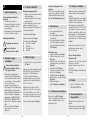
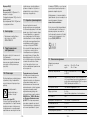
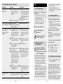
13.Betriebsstörungen
Störung Ursache Abhilfe
Sensor ohne Spannung ■Sicherung hat ausge-
löst, nicht eingeschal-
tet, DALI-Leitung
unterbrochen
■Kurzschluss
■Sicherung einschal-
ten, tauschen; Netz-
schalter einschal-
ten, DALI- Leitung
mit Spannungs prüfer
überprüfen
■Anschlüsse überprüfen
Helligkeitswert wird
nicht übermittelt ■Leitung unterbrochen
■DALI Spannungs-
versorgung defekt
■Leitung kontrollieren
Sensor sendet
unerwünscht
Bewegungssignal
■Störfaktor z. B. Venti-
lator, Klimaanlage oder
andere Wärmequelle
befindet sich im Erfas-
sungsbereich
■ Tiere bewegen sich im
Erfassungsbereich
■Wind bewegt Papier
oder Pflanzen im
Erfassungsbereich
■Sonnenlicht fällt auf
die Linse
■plötzliche Tempera-
turveränderung durch
Abluft aus Ventilatoren,
oenen Fenstern,
Klimaanlagen oder
anderen Wärmequellen
■Sensor in der Nähe
von WLAN oder
anderer Funkquelle
■Bereich umstellen
bzw. abdecken,
Abstand vergrößern
■Bereich umstellen
bzw. abdecken
■Bereich umstellen
■Sensor geschützt
anbringen oder
Bereich umstellen
■Bereich verändern,
Montageort verlegen
■mindestens 2 m von
der Funkquelle entfernt
installieren
Sensor-Reichweiten-
veränderung ■andere Umgebungs-
temperaturen ■Erfassungsbereich
durch Abdeckschalen
genau einstellen
• wenn Wartung und Pflege der
Produkte nicht entsprechend der
Bedienungsanleitung erfolgt sind,
• wenn Anbau und Installation nicht
gemäß den Installationsvorschriften
von STEINEL ausgeführt wurden,
• bei Transportschäden oder
-verlusten.
Diese Herstellergarantie lässt Ihre
gesetzlichen Rechte unberührt. Die
hier beschriebenen Leistungen gelten
zusätzlich zu den gesetzlichen Rechten
und beschränken oder ersetzen diese
nicht.
Die Garantie gilt für sämtliche STEINEL-
Produkte, die in Deutschland gekauft
und verwendet werden. Es gilt
deutsches Recht unter Ausschluss des
Übereinkommens der Vereinten
Nationen über Verträge über den
internationalen Warenkauf (CISG).
Geltendmachung
Wenn Sie Ihr Produkt reklamieren
wollen, senden Sie es bitte vollständig
und frachtfrei mit dem Original-Kaufbe-
leg, der die Angabe des Kaufdatums
und der Produkt bezeichnung enthalten
muss, an Ihren Händler oder direkt an
uns, die STEINEL Vertrieb GmbH
– Reklamationsabteilung –,
Dieselstraße 80-84, 33442
Herzebrock-Clarholz. Wir empfehlen
Ihnen daher, Ihren Kaufbeleg bis zum
Ablauf der Garantiezeit sorgfältig
aufzubewahren. Für Transportkosten
und -risiken im Rahmen der
Rücksendung übernehmen wir keine
Haftung.
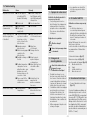
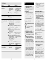
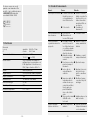
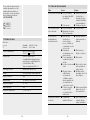
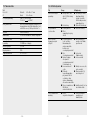
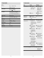
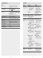
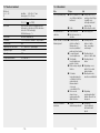
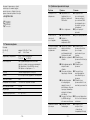
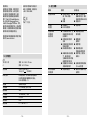
12.Technische Daten
Abmessungen
B × H × T
Ø
eckig: 80 × 80 × 51 mm
rund: 94 × 55 mm
Versorgungsspannung 4 mA / 2 DALI-Teilnehmer
12-22,5V , (no SELV)
DALI-Schnittstelle DALI-Steuerleitung (multimasterfähig zur
Kommunikation mit DALI Application Controller/
DALI-Sensor), DALI-Startup-time < 1 s
Sensorik Passiv Infrarot (IR)
Reichweite 4 × 4 m Präsenz, radial, tangential
Erfassungswinkel 360°
Lichtmessung 10-1000Lux, ∞/Tageslicht
Montagehöhe 2,5-4m
Schutzart IP20
Temperaturbereich 0°C bis + 40°C
HERSTELLER
1
3
JAHR
DEU
GARANTIE
5
HERSTELLER
GARANTIE
HERSTELLER
GARANTIE

- 16 - - 17 -
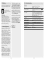
GB
1. About this document
Please read carefully and keep in a
safe place.
– Under copyright. Reproduction
either in whole or in part only with
our consent.
– Subject to change in the interest
of technical progress.
Symbols
Hazard warning!
Reference to other
information in the document.
2. General safety
precautions
!
Disconnect the power
supply before attempting
any work on the unit.
• During installation, the electric
power cable to be connected
must not be live. Therefore, switch
o the power first and use a volt-
age tester to make sure the wiring
is o-circuit.
• Installing the sensor involves work
on the mains power supply. This
work must therefore be carried
out correctly in accordance with
applicable national wiring regu-
lations and electrical operating
conditions. (e.g.: DE: VDE 0100,
AT: OVE-EN 1, CH: SEV 1000)
• Only use genuine replacement parts.
• Repairs may only be made by
specialist workshops.
3. IR Quattro SLIM XS
Proper use
– Presence detector only suitable
for mounting on indoor ceilings.
– A device box with a depth of at
least 57 mm is required.
The sensor is connected to the
control unit via a DALI bus.
The sensor uses the DALI line for
communication and for supplying
power.
Package contents (Fig. 3.1)
Product dimensions (Fig. 3.2)
Product components (Fig. 3.3)
A Sensor module
B Decorative trim panel
C Sensor lens
D Connecting terminal
4. Electrical connection
• Switch OFF power supply.
(Fig.4.1)
Wiring up the sensor switch: under
section 6 of VDE0100520, a mul-
ti-core lead containing both the mains
voltage leads as well as the control
leads (e.g. NYM 5×1.5mm²) may be
used for the wiring between sensor
and DALI Application Controller.
The lead between DALI Application
Controller and sensor must be no
longer than 300 m (with 1.5mm²).
After installing and switching ON,
the sensor flashes for 40 seconds.
Connecting the mains power supply
lead (Fig. 4.1)
...
!
Note on parallel connection:
Several sensors can be connected
in a DALI-2 system. In this case,
the maximum number of DALI users
must not be exceeded
(➜ "12.Technical specifications")
5. Mounting
• Check all components for
damage.
• Do not use the product if it is
damaged.
• Select an appropriate mounting
location, taking the reach and mo-
tion detection into consideration.
(Fig. 5.1 / 5.2)
Mounting procedure
• Switch o power supply (Fig.4.1)
• Detach decorative trim panel from
frame. (Fig.5.3)
• Fit mounting box Ø max. 68 mm
into the ceiling cut-out. (Fig.5.4)
• Connect to the mains power
supply. (Fig.5.5)
• Fit sensor module and screw into
place. (Fig.5.6)
• Fit decorative trim panel. (Fig.6.3)
• Switch ON power supply.
(Fig.6.3)
• Make settings.
(➜ "7.Function / operation")
6. Changing the detection
zone
Detection zone (Fig. 6.1 / 6.2)
The film shroud provided is used
for minimising the detection zone
by a maximum of 40%.
7. Function / operation
Once you have connected the unit
and fitted the designer panel, you
are ready to put the system into
operation.
The sensor is put into operation
in accordance with the applicable
DALI-2 standard. All functions and
commands are available from DALI
standard IEC62386 Part101,
Part103, Part303 and Part304. The
motion detection values and light
levels measured by the sensor can be
requested from the DALI Application
Controller. Automatic or time-based
cyclical transmission can also be
selected.
You will find detailed information
in the interface description on the
Internet at: DALI-2.steinel.de
LED function:
Red LED
Initialisation: LED flashes once every
2seconds
Normal mode: LED stays OFF.
DALI identification: LED flashes once
a second.
8. Accessories
– Kaiser hollow-wall box
EAN 4007841000370
9. Care / maintenance
The product requires no mainte-
nance.
The detector lens may be cleaned
with a damp cloth if it gets dirty (do
not use cleaning agents).

- 19 -- 18 -
Making Claims
If you wish to make a claim, please
send your product complete and
carriage paid with the original receipt
of purchase, which must show
the date of purchase and product
designation, either to your retailer or
contact us at STEINEL (UK)
Limited, 25Manasty Road,
Axis Park, Orton Southgate,
Peterborough, PE2 6UP, for a
returns number. For this reason,
we recommend that you keep your
receipt of purchase in a safe place
until the warranty period expires.
STEINEL shall assume no liability
for the costs or risks involved in
returning a product.
For information on making claims
under the terms of the warranty,
please go to www.steinel-
professional.de/garantie
If you have a warranty claim or would
like to ask any question regarding
your product, you are welcome to
call us at any time on our Service
Hotline 01733 366700.
MANUFACTURER'S
1
3
5
YEAR
GB
WARRANTY
MANUFACTURER'S
YEAR
WARRANTY
MANUFACTURER'S
YEAR
WARRANTY
10. Disposal
Electrical and electronic equipment,
accessories and packaging must
be recycled in an environmentally
compatible manner.
Do not dispose of electrical
and electronic equipment
as domestic waste.
EU countries only:
Under the current European Directive
on Waste Electrical and Electronic
Equipment and its implementation in
national law, electrical and electronic
equipment no longer suitable for
use must be collected separately
and recycled in an environmentally
compatible manner.
11. Manufacturer's Warranty
As purchaser, you are entitled to your
statutory rights against the vendor.
If these rights exist in your country,
they are neither curtailed nor re-
stricted by our Warranty Declaration.
We guarantee that your STEINEL
Professional sensor product will re-
main in perfect condition and proper
working order for a period of 5years.
We guarantee that this product is
free from material-, manufactur-
ing- and design flaws. In addition,
we guarantee that all electronic
components and cables function
in the proper manner and that all
materials used and their surfaces are
without defects.
12.Technical specifications
Dimensions
W × H × D
Ø
Square: 80 × 80 × 51 mm
Round: 94 × 55 mm
Power supply 4 mA / 2 DALI users
12-22.5V , no SELV
DALI-Startup-time < 1 s
DALI interface DALI control line (multi-master capability for
communication with the DALI Application
Controller/DALI sensor),
DALI-Startup-time < 1 s
Sensor system Passive infrared (IR)
Reach 4 × 4 m presence, radial, tangential
Angle of coverage 360°
Light measurement 10-1000 lux, ∞/daylight
Mounting height 2.5 - 4 m
IP rating IP20
Temperature range 0°C to 40°C

- 21 -- 20 -
FR
1. À propos de ce document
Veuillez le lire attentivement et le
conserver en lieu sûr !
– Il est protégé par la loi sur les
droits d'auteur. Une réimpression
même partielle n'est autorisée
qu'après notre accord préalable.
– Sous réserve de modifications
techniques.
Explication des symboles
Attention danger !
Renvoi à des passages dans
le document.
2. Consignes de
sécurité générales
!
Avant toute intervention sur
l'appareil, couper
l'alimentation électrique !
• Pendant le montage, les con-
ducteurs à raccorder doivent être
hors tension. Il faut donc d'abord
couper l'alimentation électrique et
s'assurer de l'absence de courant
à l'aide d'un testeur de tension.
• L'installation du détecteur implique
une intervention sur le réseau
électrique. Elle doit donc être
eectuée correctement et con-
formément aux directives locales
d'installation et aux conditions de
raccordement.
• Utiliser uniquement des pièces de
rechange d'origine.
• Les réparations ne doivent être
eectuées que par des ateliers
spécialisés.
3. IR Quattro SLIM XS
Utilisation conforme aux prescrip-
tions
– Le détecteur de présence
ne convient qu'au montage au
plafond à l'intérieur des bâtiments.
– Un boîtier d'encastrement d'au
moins 57 mm de profondeur est
nécessaire.
Un bus DALI permet de connecter le
détecteur au contrôleur.
Le détecteur utilise le câble DALI pour
la communication et l'alimentation
en tension.
Contenu de la livraison (fig. 3.1)
Dimensions du produit (fig. 3.2)
Vue d'ensemble de l'appareil (fig. 3.3)
A Module de détection
B Capot
C Lentille du détecteur
D Borne de raccord
4. Branchement électrique
• Couper l'alimentation électrique.
(Fig.4.1)
Ce qui suit s'applique au câblage de
l'interrupteur type encastré : selon la
norme VDE 0100 520 (correspondant
à la norme NF C-15100), partie 6, une
ligne multiple peut être utilisée pour le
câblage entre le détecteur et le contrô-
leur d'applications DALI, comprenant
aussi bien des câbles d’alimentation
que des câbles de commande (par ex.
NYM 5 × 1,5 mm²).
...
!
13.Troubleshooting
Malfunction Cause Remedy
No power at the sensor ■Fuse has tripped,
not switched ON,
break in DALI wiring
■Short circuit
■Activate, change fuse,
turn ON mains switch,
check DALI wiring with
voltage tester
■Check connections
Light level not being
communicated ■Break in wiring
■DALI power
supply faulty
■Check cable
Sensor sending motion
detection signal when
it should not
■There is interference,
e.g. fan, air-condition-
ing system or other
source of heat, in the
detection zone
■ Animals moving in
detection zone
■Wind is moving paper
or plants in the
detection zone
■Sunlight is shining on
the lens
■Sudden temperature
change due to air ex-
pelled from fans, open
windows, air-condi-
tioning systems or oth-
er sources of heat
■Sensor near Wi-Fi or
other wireless commu-
nication source
■Adjust detection zone
or fit shrouds, increase
distance
■Adjust zone
or fit shrouds
■Change detection
zone
■Mount sensor in
a protected place
or change zone
■Adjust detection zone
or install in a dier-
ent place
■Install at least 2 m
away from the
wireless communica-
tion source
Sensor reach change ■Diering ambient
temperatures ■Use shrouds to
define detection zone
precisely

- 22 - - 23 -
ils existent dans votre pays. Nous
vous accordons une garantie de
5ans sur le parfait état et le bon
fonctionnement de votre produit à
détection STEINEL Professional.
Nous garantissons que ce produit ne
présente pas de défauts matériels,
de fabrication ni de construction.
Nous garantissons le bon état de
fonctionnement de tous les compo-
sants électroniques et des câbles
ainsi que l’absence de vices pour
tous les matériaux utilisés et leurs
surfaces.
Réclamation
Si vous avez une réclamation à faire
au sujet de votre produit, veuillez
contacter votre revendeur en lui four-
nissant la preuve d'achat originale
qui doit comporter la date de l’achat
et la désignation du produit.
Veuillez consulter notre site Internet
www.steinel-professional.de/
garantie pour de plus amples infor-
mations sur la manière de faire valoir
un droit à une prestation de garantie.
Si vous avez besoin d’avoir recours
au service de garantie ou si vous
avez une question au sujet de votre
produit, vous pouvez nous appeler
à tout moment au n° d’assistance
téléphonique pour la clientèle
03 20 30 34 00.
1
3
5
FR
DE GARANTIE
AN
FABRICANT DE GARANTIE
ANS
FABRICANT
DE GARANTIE
ANS
FABRICANT
8. Accessoires
– Boîte pour parois creuses Kaiser
N° EAN : 4007841000370
9. Entretien/Maintenance
Le produit ne nécessite aucun
entretien.
Si la lentille de détection se salit, la
nettoyer avec un chion humide (ne
pas utiliser de détergent).
10. Recyclage
Les appareils électriques, lesac-
cessoireset les emballages doivent
êtresoumis à un recyclage respectu-
eux de l'environnement.
Ne pas jeter les appareils
électriques avec les ordures
ménagères !
Uniquement pour les pays de l'UE :
Conformément à la directive europé-
enne en vigueur relative aux appareils
électriques et électroniques usagés
et à son application dans le droit
national, les appareilsélectriques qui
ne fonctionnent plus doiventêtrecoll-
ectés séparément des ordures mé-
nagères et doiventfairel'objetd'un
recyclage écologique.
11. Garantie du fabricant
En tant qu’acheteur, vous disposez
des droits prescrits par la loi à l’en-
contre du vendeur. Notre déclaration
de garantie ne raccourcit ni ne
limite ces droits dans la mesure où
La longueur maximale des câbles
entre le contrôleur d'applications DALI
et le détecteur ne doit pas dépasser
300 m (pour 1,5 mm²). Le détecteur
commence ensuite à clignoter pour
40 secondes après l'installation et la
mise sous tension.
Branchement du câble secteur
(fig. 4.1)
Remarque concernant le
branchement en parallèle :
Il est possible de connecter plusieurs
détecteurs dans un système DALI-2.
Il faut alors respecter le nombre
maximum de participants DALI
(➜«12. Caractéristiques
techniques»)
5. Montage
• Contrôler l'absence de dommages
sur toutes les pièces.
• Ne pas mettre le produit en
service en cas de dommage.
• Choisir l'emplacement de mon-
tage approprié en tenant compte
de la portée et de la détection des
mouvements. (Fig.5.1/5.2)
Étapes de montage
• Couper l'alimentation au courant.
(Fig.4.1)
• Enlever le capot du cadre.
(Fig.5.3)
• Insérer la boîte d'encastrement de
Ø max. 68 mm dans la découpe
au plafond. (Fig.5.4)
• Procéder au raccordement au
secteur. (Fig.5.5)
• Introduire le module de détection
et visser. (Fig.5.6)
• Emboîter le capot. (Fig.6.3)
• Mettre l'appareil sous tension.
(Fig.6.3)
• Procéder aux réglages.
(➜ « 7. Fonction/Commande »)
6. Modifier la zone de
détection
Zone de détection (fig. 6.1/6.2)
Le cache également fourni sert
à minimiser la zone de
détection au maximum de 40 %.
7. Fonction/Commande
Après avoir procédé au branchement,
avoir enfiché le capot, vous pouvez
mettre l'installation en service.
La mise en service a lieu conformé-
ment à la norme DALI-2 en vigueur.
Toutes les fonctions et commandes
de la norme DALI CEI 62386 partie
101, partie 103, partie 303 et partie
304 sont disponibles. Le contrôleur
d'applications DALI peut consulter
lesvaleurs de luminosité et de mou-
vement mesurées par le détecteur.
Un envoi cyclique automatique
ou basé sur le temps est, en plus,
possible.
Vous trouverez des informations
détaillées dans la description de
l'interface disponible sur Internet à
l'adresse : DALI-2.steinel.de
Fonctions de la LED
LED rouge
Initialisation : la LED clignote une fois
toutes les 2 secondes.
Fonctionnement normal : la LED reste
éteinte.
Identification DALI : la LED clignote
toutes les secondes.

- 25 -- 24 -
13. Dysfonctionnements
Problèmes Causes Solutions
Le détecteur n'est pas
sous tension ■Fusible a sauté
appareil hors circuit,
câble DALI coupé
■Court-circuit
■Enclencher le fusible,
le remplacer ; mettre
l'interrupteur en circuit,
vérifier le câble DALI à
l'aide d'un testeur de
tension
■Vérifier le branchement
La valeur de luminosité
n'est pas transmise ■Câble coupé
■Alimentation en tensi-
on DALI défectueuse
■Contrôler le câble
Le détecteur envoie
un signal de mouvement
non souhaité
■Un facteur de pertur-
bation, par ex. un ven-
tilateur, une climati-
sation ou une autre
source de chaleur, se
trouve dans la zone de
détection
■ Des animaux se dépla-
cent dans la zone de
détection
■Le vent agite du papier
ou des plantes dans la
zone de détection
■Rayons solaires sur
la lentille
■Variations subites de
la température dues à
des courants d'air pro-
venant de ventilateurs,
de fenêtres ouvertes,
de climatisations ou
d'autres sources de
chaleur
■Le détecteur est placé
à proximité du la WiFi
ou d'une autre sour-
ce radio
■Modifier la zone ou la
masquer, augmenter la
distance
■Modifier la zone
ou la masquer
■Modifier la zone
■Installer le détecteur
dans un endroit proté-
gé ou modifier la zone
■Modifier la zone, mon-
ter l'appareil à un aut-
re endroit
■Installer le détecteur
au moins à 2 m de la
source radio
Modification de la portée
du détecteur ■Variations de la tem-
pérature ambiante ■Réglage de précisi-
on de la zone de dé-
tection par caches en-
fichables
12. Caractéristiques techniques
Dimensions
l × H × P
Ø
carré : 80 × 80 × 51 mm
rond : 94 × 55 mm
Tension d'alimentation 4 mA / 2 participants DALI
12-22,5V , (no SELV)
Interface DALI Câble de commande DALI (compatible multi-
maître pour la communication avec le contrôleur
d'applications DALI/détecteur DALI),
Durée de démarrage DALI < 1 s
Technologie de détection Détecteur infrarouge passif (IR)
Portée 4 × 4 m présence, portée radiale, portée tangentielle
Angle de détection 360°
Mesure de la luminosité de 10 à 1000 lx, ∞ / lumière diurne
Hauteur d'installation de 2,5 à 4 m
Indice de protection IP20
Plage de température de 0 °C à + 40 °C

- 26 - - 27 -
NL
1. Over dit document
Zorgvuldig doorlezen en
bewaren a.u.b.!
– Rechten uit het auteursrecht voor-
behouden. Vermenigvuldiging, ook
van delen van deze handleiding,
is alleen met onze toestemming
geoorloofd.
– Wijzigingen in het kader van de
technische vooruitgang voorbe-
houden.
Toelichting van de symbolen
Waarschuwing voor gevaar!
Verwijzing naar tekstpassa-
ges in het document.
2. Algemene
veiligheidsvoorschriften
!
Voor alle werkzaamheden
aan het apparaat dient de
spanningstoevoer te worden
onderbroken!
• Bij de montage moet de aan
te sluiten elektrische kabel
spanningsvrij zijn. Daarom eerst
de stroom uitschakelen en op
spanningsloosheid testen met een
spanningstester.
• Bij de installatie van de sensor
wordt met netspanning gewerkt.
Dit moet vakkundig en volgens de
gebruikelijke installatievoorschrif-
ten en aansluitingsvoorwaarden
worden uitgevoerd. (bijv.:
DE: VDE 0100, AT: OVE-EN 1,
CH: SEV 1000).
• Gebruik uitsluitend originele
reserveonderdelen.
• Reparaties mogen uitsluitend door
een gespecialiseerd bedrijf worden
uitgevoerd.
3. IR Quattro SLIM XS
Gebruik volgens de voorschriften
– Aanwezigheidsmelder alleen
geschikt
voor plafondmontage binnenshuis.
– Contactdoos met een min. diepte
van 57 mm vereist.
De sensor wordt m.b.v. een DALI-bus
gekoppeld aan het besturingsap-
paraat.
De sensor gebruikt de DALI-kabel
voor de communicatie en voor de
stroomvoorziening.
Bij de levering inbegrepen (afb. 3.1)
Productafmetingen (afb. 3.2)
Overzicht apparaat (afb. 3.3)
A Sensormodule
B Designkap
C Sensorlens
D Aansluitklem
4. Elektrische aansluiting
• Stroomtoevoer uitschakelen
(afb. 4.1)
Voor de aansluiting van de
sensorschakelaar geldt: volgens
VDE0100520 punt 6 mag voor
de bekabeling tussen sensor en
DALI Application Controller een
meervoudige leiding worden gebruikt,
die zowel de netspanningskabels
als de regelkabels bevat (bijv. NYM
5×1,5mm²).
...
!
De kabellengte tussen DALI Appli-
cation Controller en sensor mag niet
groter zijn dan 300m (bij 1,5mm²).
Na de installatie en het inschakelen
begint de sensor 40 seconden te
knipperen.
Aansluiting van de stroomtoevoer
(afb. 4.1)
Opmerking voor een parallelle
schakeling:
In een DALI-2-systeem kunnen
meerdere sensoren worden aange-
sloten. Daarbij moet rekening worden
gehouden met het maximale aantal
DALI-deelnemers
(➜ '12.Technische gegevens')
5. Montage
• Alle onderdelen controleren op
beschadigingen.
• Neem het product bij beschadigin-
gen niet in gebruik.
• Kies een passende montage-
plaats; houd hierbij rekening met
de reikwijdte en de bewegingsre-
gistratie. (afb.5.1/5.2)
Montagestappen
• Stroomtoevoer uitschakelen
(afb. 4.1).
• Designplaat losmaken van raam
(afb. 5.3).
• Inbouwdoos Ø max. 68 mm
in de plafondopening plaatsen
(afb. 5.4).
• Netaansluitingen maken (afb. 5.5)
• Sensormodule plaatsen en vast-
schroeven (afb. 5.6).
• Designplaat aanbrengen (afb. 6.3).
• Stroomtoevoer inschakelen (afb. 6.3).
• Instellingen uitvoeren
(➜ '7.Werking/bediening')
6. Registratiebereik
aanpassen
Registratiebereik (afb. 6.1/6.2)
Met de meegeleverde afdekfolie kan
het registratiebereik met max. 40%
worden verkleind.
7. Werking/bediening
Nadat de aansluiting is uitgevoerd en
de designplaat geplaatst, kan de in-
stallatie in gebruik worden genomen.
De ingebruikneming wordt volgens
de actuele DALI-2-norm uitgevoerd.
Alle functies en commando's uit de
DALI-norm IEC 62386 deel101,
deel103, deel303 en deel304 staan
ter beschikking. De door de sensor
berekende waarden voor bewegingen
en lichtsterkte kunnen door de
DALI Application Controller worden
opgevraagd. Bovendien bestaat de
mogelijkheid om deze automatisch of
cyclisch op tijdbasis te verzenden.
Uitgebreide informatie vindt u in de
interfacebeschrijving op het internet
onder: DALI-2.steinel.de
Led-functie:
Rode led
Initialiseren: led knippert 1×om de
2seconden
Normaal bedrijf: led blijft uit.
DALI-identificatie: led knippert snel.

- 29 -- 28 -
van uw sensorproduct uit het
STEINEL Professional assortiment.
Wij garanderen dat dit product geen
materiaal-, productie- of construc-
tiefouten heeft. Wij garanderen de
goede werking van alle elektronische
componenten en kabels, alsook dat
alle toegepaste materialen en hun
oppervlakken vrij van gebreken zijn.
Garantie claimen
Als u aanspraak wilt maken op
garantie, dan kunt u het betreende
artikel, compleet samen met het
originele aankoopbewijs en de
klachtomschrijving, terugsturen naar
uw leverancier of direct naar
Van Spijk Agenturen, De Scheper
402, 5688 HP Oirschot. Wij
adviseren u daarom uw aankoop-
bewijs zorgvuldig te bewaren tot de
garantieperiode is verlopen. STEINEL
kan niet aansprakelijk worden gesteld
voor de transportkosten en het trans-
portrisico van het terugsturen.
(Op onze website
www.vanspijk.nl vindt u meer
informatie over het claimen van
garantierechten)
Als u een garantie-aanvraag heeft of
technische vragen betreende uw
product, kunt u contact opnemen
met onze helpdesk +31 499 551490.
1
3
5
NL
FABRIEKS
JAAR
GARANTIE FABRIEKS
JAAR
GARANTIE
FABRIEKS
JAAR
GARANTIE
8. Toebehoren
– Holle Kaiser-wandcontactdoos
EAN 4007841000370
9. Onderhoud/verzorging
Dit product is onderhoudsvrij.
De registratielens kan bij vervuiling
met een vochtige doek (zonder
schoonmaakmiddel) worden
gereinigd.
10. Verwijderen
Elektrische apparaten, toebehoren en
verpakkingen dienen milieuvriendelijk
gerecycled te worden.
Doe elektrische apparaten
niet bij het huisvuil!
Alleen voor EU-landen:
Conform de geldende Europese
richtlijn voor verbruikte elektrische
en elektronische apparatuur en hun
implementatie in nationaal recht, die-
nen niet langer bruikbare elektrische
apparaten gescheiden ingezameld
en milieuvriendelijk gerecycled te
worden.
11. Fabrieksgarantie
Als koper heeft u t.o.v. de verkoper
recht op de wettelijk voorgeschreven
garantie. Voor zover dit recht op ga-
rantie in uw land bestaat, wordt die
door onze garantieverklaring noch
verkort, noch beperkt. Wij verlenen
5jaar garantie op de onberispelijke
staat en het correcte functioneren
12. Technische gegevens
Afmetingen
B × H × D
Ø
rechthoekig: 80 × 80 × 51 mm
rond: 94 × 55 mm
Voedingsspanning 4 mA / 2 DALI-deelnemers
12-22,5V , (no SELV)
DALI-interface DALI-regelkabel (geschikt voor multimaster voor de
communicatie met de DALI Application Controller/
DALI-sensor), DALI-opstarttijd < 1 sec.
Sensor passief-infrarood (IR)
Reikwijdte 4 × 4 m aanwezigheid, radiaaln, tangentiaal
Registratiehoek 360°
Lichtmeting 10 – 1000 lux, ∞/daglicht
Montagehoogte 2,5-4 m
Bescherming IP20
Temperatuurbereik 0 °C tot 40 °C

- 30 - - 31 -
13. Storingen
Storing Oorzaak Oplossing
Sensor zonder
netspanning ■Zekering gesprongen,
niet ingeschakeld,
DALI-leiding onder-
broken
■Kortsluiting
■Zekering inschakelen,
vervangen; netschake-
laar inschakelen,
DALI-kabel met span-
ningzoeker controleren
■Aansluitingen
controleren
Lichtsterktewaarde wordt
niet doorgestuurd ■Kabel onderbroken
■DALI-stroomvoorzie-
ning defect
■Kabel controleren
Sensor verstuurt onge-
wenst een bewegings-
signaal
■Storende factor zoals
ventilator, airconditio-
ning of andere warm-
tebron bevindt zich in
het registratiebereik
■ Er zijn bewegende die-
ren in het registratie-
bereik
■Wind beweegt papier
of planten binnen het
registratiebereik
■Er valt zonlicht op
de lens
■Plotselinge verandering
van temperatuur door
afvoerlucht van ventila-
toren, open ramen, air-
conditioning of andere
warmtebronnen
■Sensor in de buurt van
WiFi of andere draad-
loze bron
■Bereik veranderen
resp. afschermen,
afstand vergroten
■Bereik veranderen of
afdekken
■Bereik veranderen
■Sensor afschermen of
bereik veranderen
■Bereik veranderen,
andere montageplaats
kiezen
■Minimaal 2 m van de
draadloze bron af in-
stalleren
Verandering
sensorreikwijdtes ■Andere omgevings-
temperaturen ■Registratiebereik met
behulp van afdekplaat-
jes nauwkeurig
instellen
IT
1. Riguardo a questo
documento
Si prega di leggerlo attentamente e
di conservarlo!
– Tutelato dai diritti d'autore. La
ristampa, anche solo di estratti,
è consentita solo previa nostra
approvazione.
– Con riserva di modifiche legate al
progresso della tecnica.
Spiegazione dei simboli
Avvertimento contro pericoli
Rimando a passaggi nel
documento.
2. Avvertenze generali
relative alla sicurezza
!
Prima di eettuare qualsiasi
lavoro sull'apparecchio,
togliere sempre la corrente!
• Durante il montaggio la linea
elettrica deve essere scollegata.
Prima del lavoro, occorre pertanto
togliere la tensione e accertarne
l'assenza mediante uno strumento
di misurazione della tensione.
• L'installazione del sensore è un
lavoro che richiede un intervento
sulla tensione di rete. Essa deve
quindi venire eettuata a regola
d'arte secondo le prescrizioni per
l'installazione e alle condizioni di
allacciamento applicate nel singolo
paese (per es.: DE: VDE 0100,
AT: OVE-EN 1, CH: SEV 1000).
• Utilizzare esclusivamente pezzi di
ricambio originali.
• Le riparazioni devono essere eet-
tuate esclusivamente da ocine
specializzate.
3. IR Quattro SLIM XS
Utilizzo adeguato allo scopo
– Rilevatore di presenza adatto
solo per il montaggio a sotto in
ambienti interni.
– È necessaria una presa dell'ap-
parecchio con una profondità di
almeno 57 mm.
Con un bus DALI il sensore viene col-
legato all'apparecchio di comando.
Il sensore utilizza la linea DALI per
comunicare con la LiveLink Box e per
fornire corrente elettrica.
Volume di fornitura (Fig. 3.1)
Dimensioni dell'apparecchio (Fig. 3.2)
Panoramica degli apparecchi
(Fig. 3.3)
A Modulo sensore
B Copertura decorativa
C Lente del sensore
D Morsetto di allacciamento
4. Allacciamento elettrico
• Staccare l'alimentazione di
corrente (Fig.4.1)
Per il cablaggio dell'interruttore a sen-
sore vale quanto segue: ai sensi della
norma VDE 0100520 capitolo 6 per il
cablaggio tra sensore e DALI App-
lication Controller è consentito
utilizzare un conduttore multiplo che
contenga sia i cavi della tensione di
rete sia quelli di comando (per es.
NYM 5×1,5mm²).
...
!

- 32 - - 33 -
11. Garanzia del produttore
Quale acquirente Lei può rivendicare
nei confronti del venditore i diritti
previsti dalla legge. Nella misura in
cui tali diritti esistono nel Suo paese,
la nostra dichiarazione di garanzia né
li riduce né li limita. Noi Le concedia-
mo 5anni di garanzia dell’impec-
cabile costituzione e del regolare
funzionamento del Suo prodotto a
sensori STEINEL Professional. Noi
garantiamo che questo prodotto è
privo di difetti di produzione e co-
struzione. Garantiamo la funzionalità
di tutti i componenti elettronici e di
tutti i cavi nonché l’assenza di vizi di
tutti i materiali impiegati e delle loro
superfici.
Rivendicazione
Se ha intenzione di esporre reclamo
in merito al prodotto da Lei acqui-
stato, La si prega di trasmettere tale
reclamo completo e arancato as-
sieme allo scontrino d’acquisto o alla
fattura indicante la data dell’acquisto
e la denominazione del prodotto
al Suo rivenditore o direttamente
a noi: STEINEL Italia S.r.l., Largo
Donegani 2, I-20121 Milano. Le
consigliamo pertanto di conservare
scrupolosamente lo scontrino d’ac-
quisto o la fattura fino alla scadenza
del periodo di garanzia. La STEINEL
declina ogni responsabilità per costi
e rischi legati al trasporto nell’ambito
della restituzione del prodotto.
(Per informazioni in merito alla riven-
dicazione di un diritto di garanzia si
prega di consultare il nostro sito web
www.steinel.it)
8. Accessori
– Presa da parete cava Kaiser
EAN 4007841000370
9. Cura/manutenzione
Il prodotto non necessita di manu-
tenzione.
In caso la lente di rilevamento fosse
imbrattata, pulirla con un panno umi-
do (senza utilizzare detergenti).
10. Smaltimento
Apparecchi elettrici, accessori e
materiali d'imballaggio devono essere
consegnati a un centro di riciclaggio
riconosciuto.
Non gettate gli apparecchi
elettrici assieme ai rifiuti
domestici!
Solo per paesi UE:
conformemente alla Direttiva Europea
vigente in materia di rifiuti di appa-
recchi elettrici ed elettronici e alla
sua attuazione nel diritto nazionale,
gli apparecchi elettrici ed elettronici
non più idonei all'uso devono essere
separati dagli altri rifiuti e consegnati a
un centro di riciclaggio riconosciuto.
Non superare la lunghezza massima
consentita del cavo di collegamento
tra DALI Application Controller e
sensore pari a 300 m (nel caso
di 1,5mm²). Dopo l'installazione
e l'accensione il sensore inizia a
lampeggiare per 40 secondi.
Allacciamento del cavo di collega-
mento alla rete (Fig. 4.1)
Avvertenza sul collegamento in
parallelo:
In un sistema DALI-2 si possono
allacciare più sensori. Qui occorre te-
nere presente la quantità massima di
utenze DALI collegabili (cfr. Dati tecni-
ci a pagina (➜ "12.Dati tecnici")
5. Montaggio
• Controllare tutti i componenti per
verificare se presentano danneg-
giamenti.
• In caso di danni non mettere in
funzione il prodotto.
• Scegliere un luogo di montaggio
adeguato tenendo conto del
raggio d'azione e del rilevamento
del movimento. (Fig.5.1/5.2)
Fasi di montaggio
• Staccare l'alimentazione di corren-
te. (Fig.4.1)
• Rimuovere la copertura decorativa
dal telaio. (Fig.5.3)
• Inserire la presa di montaggio
Ø max. 68 mm nell'intaglio del
sotto. (Fig.5.4)
• Eettuare gli allacciamenti di rete.
(Fig.5.5)
• Inserire il modulo sensore e
avvitarlo. (Fig.5.6)
• Infilare la copertura decorativa.
(Fig.6.3)
• Attivare l'alimentazione di corrente.
(Fig.6.3)
• Eettuare le dovute impostazioni.
(➜ "7.Funzionamento/
comando")
6. Modifica del campo di
rilevamento
Campo di rilevamento (Fig. 6.1/6.2)
La pellicola di schermatura fornita in
dotazione serve a minimizzare il cam-
po di rilevamento del max. 40%.
7. Funzionamento/comando
Dopo aver completato l'allacciamento
e applicato la copertura decorativa,
potrete mettere in funzione l'impianto.
La messa in funzione avviene confor-
memente alla norma DALI-2 in vigore.
Sono a disposizione tutte le funioni e
tutti i comandi della norma DALI IEC
62386 Parte 101, Parte 103, Parte
303 e Parte 304. I valori di movimento
e di luminosità in tal modo rilevati
possono essere interrogati dal DALI
Application Controller. Vi è inoltre la
possibilità di un invio automatico o
ciclico in base al tempo.
Trovate informazioni dettagliate nella
descrizione dell'interfaccia in Internet
al sito: DALI-2.steinel.de
Funzione LED:
LED rosso
Inizializzazione: il LED lampeggia
1 × ogni 2 secondi
Funzionamento normale: il LED
rimane spento.
Identificazione DALI: il LED lampeggia
al ritmo di un secondo.

- 34 - - 35 -
13. Disturbi di funzionamento
Guasto Causa Rimedio
Sensore privo di tensione ■Il fusibile è intervenuto,
interruttore non acce-
so, linea di alimenta-
zione DALI interrotta
■Corto circuito
■Attivare o sostituire il
fusibile; accendere l'in-
terruttore di rete; con-
trollare la linea di ali-
mentazione DALI con
un voltmetro
■Controllare gli
allacciamenti
Il valore di luminosità non
viene trasmesso ■Linea interrotta
■Alimentazione di
tensione DALI guasta
■Controllare la linea
Il sensore trasmette
segnale di movimento a
sproposito
■Nel campo di rileva-
mento si trova un fat-
tore d'interferenza, per
es. ventilatore, impian-
to di climatizzazione o
altra fonte di calore
■ Animali in movimen-
to nel campo di rile-
vamento
■Il vento muove carta o
piante nel campo di
rilevamento
■La luce del sole
cade direttamente
sulla lente
■Improvviso sbalzo di
temperatura dovuto
ad aria di scarico pro-
veniente da ventilatori,
finestre aperte, im-
pianti di climatizza-
zione o altre fonti di
calore
■Sensore nelle vicinanze
di WLAN o altra
fonte radio
■Adattare o coprire il
campo, aumentate la
distanza
■Cambiare o coprire il
campo di rilevamento
■Spostare il campo
■Applicare il sensore in
modo tale che sia
protetto o modificare
il campo
■Modificare il campo
o spostare il luogo di
montaggio
■Installare almeno a 2 m
dalla fonte radio
Modifica del raggio
d'azione del sensore ■Diverse temperature
ambiente ■Regolare esattamente
il campo di rilevamento
con le schermature
Se dovesse esporre un caso di
garanzia o una domanda sul Suo
prodotto, ci può contattare al numero
+39/02/96457231 dal lunedì al
venerdì dalle 9:00 alle 18:00.
DI GARANZIA
3
5
ANNO
IT
DEL PRODUTTORE
DI GARANZIA
ANNI
DEL PRODUTTORE
DI GARANZIA
ANNI
DEL PRODUTTORE
12. Dati tecnici
Dimensioni
l × a × p
Ø
squadrato: 80 × 80 × 51 mm
rotondo: 94 × 55 mm
Tensione di alimentazione 4 mA / 2 utenze DALI
12-22,5V , (no SELV)
Interfaccia DALI Cavo di comando DALI (abilitato al
multimaster per la comunicazione con
il DALI Application Controller/sensore
DALI), Tempo di reazione DALI < 1 s
Sensori Infrarossi passivi (IR)
Raggio d'azione 4 × 4 m presenza, radiale, tangenziale
Angolo di rilevamento 360°
Misurazione luce 10-1000 Lux, ∞/luce diurna
Altezza di montaggio 2,5-4 m
Grado di protezione IP20
Intervallo di temperatura 0 °C - + 40 °C

- 36 - - 37 -
ES
1. Acerca de este documento
¡Leer detenidamente y conservar
para futuras consultas!
– Protegido por derechos de autor.
Queda terminantemente prohibida
la reimpresión, ya sea total o
parcial, salvo con autorización
expresa.
– Sujeto a modificaciones en fun-
ción del progreso técnico.
Explicación de los símbolos
¡Advertencia de peligros!
Referencia a partes de texto
en el documento.
2. Indicaciones generales de
seguridad
!
¡Antes de comenzar
cualquier trabajo en el
aparato, interrúmpase la
alimentación de tensión!
• Durante el montaje, el cable a co-
nectar ha de estar libre de tensión.
Por eso, desconecte primero la
corriente y compruebe la ausencia
de tensión con un comprobador
de tensión.
• La instalación del sensor es un
trabajo en la red eléctrica. Por
consiguiente, ha de realizarse
con la debida profesionalidad
conforme a las normativas de
instalación y condiciones de aco-
metida del respectivo país. (p.ej.,
DE:-VDE0100, AT:ÖVE-EN1,
CH:SEV1000)
• Utilice solo piezas de repuesto
originales.
• Las reparaciones solo pueden
realizarse en talleres especiali-
zados.
3. IR Quattro SLIM XS
Uso previsto
– Detector de presencia solo apto
para el montaje interior en el
techo.
– Requiere toma con un mín. de
57mm de profundidad.
Mediante un bus DALI, el sensor se
acopla al dispositivo de control.El
sensor emplea el cable DALI para la
comunicación y para la alimentación
eléctrica.
Volumen de suministro (fig. 3.1)
Dimensiones del producto (fig. 3.2)
Vista general del equipo (fig. 3.3)
A Módulo de sensor
B Cubierta decorativa
C Lente del sensor
D Borne de conexión
4. Conexión eléctrica
• Desconectar la alimentación
eléctrica. (fig.4.1)
Para el cableado de los conmutado-
res de sensor será aplicable: Según la
norma VDE0100520, apdo. 6, para
el cableado entre el sensor y el DALI
Application Controller, puede em-
plearse un cable multiconductor que
incluya tanto los hilos de alimentación
como también los hilos de mando (p.
ej., NYM 5×1,5 mm²).
...
!
La longitud máxima del cable entre
DALI Application Controller y sensor
no superará los 300m (con 1,5mm²).
Una vez instalado y conectado el
sensor empieza a parpadear durante
40 segundos.
Conexión del cable de alimentación
(fig. 4.1)
Observación acerca de la conexión
en paralelo:
En un solo sistema DALI 2 pueden
conectarse varios sensores. En
tal caso, hay que tener cuenta el
número máximo de dispositivos DALI
(➜"12.Datos técnicos")
5. Montaje
• Comprobar que todos los compo-
nentes se encuentren en perfecto
estado.
• No se pongan en servicio en caso
de estar deteriorados.
• Elegir un lugar de montaje
adecuado teniendo en cuenta el
alcance y la detección de movi-
mientos. (fig.5.1/5.2)
El montaje por pasos
• Desconectar la alimentación
eléctrica. (fig.4.1)
• Retirar la cubierta decorativa del
marco. (fig.5.3)
• Instalar toma de instalación como
máx. Ø 68mm en el recorte del
techo. (fig.5.4)
• Establecer las conexiones eléctri-
cas. (fig. 5.5)
• Integrar módulo de sensor y fijarlo
con tornillos. (fig.5.6)
• Encajar la cubierta decorativa.
(fig.6.3)
• Conectar la alimentación eléctrica.
(fig.6.3)
• Llevar a cabo los ajustes.
(➜ "7. Función/Manejo")
6. Modificar campo de
detección
Campo de detección (fig.6.1/6.2)
La lámina cobertora incluida sirve
para minimizar el campo de detec-
ción como máx. un 40%.
7. Función/Manejo
Una vez realizada la conexión y
acoplada la cubierta decorativa,
la instalación puede ponerse en
funcionamiento.
La puesta en servicio tiene lugar se-
gún la norma aplicable DALI2. Están
disponibles todas las funciones y co-
mandos de la norma DALI IEC62386
parte101, parte103, parte303 y
parte304 Los valores de movimiento
y luminosidad calculados por el
sensor pueden ser consultados por el
DALI Application Controller. Adicional-
mente también puede activarse una
transmisión temporizada cíclica.
Información detallada la encontrará
en la descripción de interfaces en
Internet a través de: DALI-2.steinel.de
Funciones LED:
Led rojo
Inicialización: LED parpadea 1×cada
2segundos
Operación normal: LED permanece
apagado.
Identificación DALI: LED parpadea
una vez por segundo.

- 39 -- 38 -
sobre el estado y el funcionamiento
impecables de su producto STEINEL
Professional con técnica de senso-
res. Garantizamos que este producto
carece de defectos derivados del
material, la fabricación o construc-
ción. Garantizamos la plena funcio-
nalidad de todos los cables y piezas
electrónicas, así como la ausencia
de defectos en cualquier material
empleado o en su superficie.
Reclamación
Si usted desea reclamar su produc-
to, envíelo, por favor, todo completo
y a porte pagado junto con el tíquet
de compra original que deberá
indicar la fecha de compra y la deno-
minación del producto a su vendedor
o directamente a nuestra dirección,
SAET-94 S.L. - C/Trepadella, n°
10, Pol. Ind. Castellbisbal Sud,
E-08755Castellbisbal (Barcelona).
Recomendamos, por eso, guardar
bien el tíquet de compra hasta que
haya expirado el período de garantía.
STEINEL no responderá por gastos
o riesgos de transporte con motivo
del envío.
Información para hacer constar un
caso de garantía la obtendrá a través
de nuestra página web
www.steinel-professional.de/
garantie
Para cualquier caso de garantía o
duda referente a su producto, nos
puede llamar al número del Servicio
Técnico +34937722849.
DE GARANTÍA
1
3
5
AÑO
ES
DE FABRICANTE
DE GARANTÍA
AÑOS
DE FABRICANTE
DE GARANTÍA
AÑOS
DE FABRICANTE
8. Accesorios
– Caja de pared hueca Kaiser
N° EAN4007841000370
9. Mantenimiento/cuidado
El producto está exento de mante-
nimiento.
En caso de ensuciarse, el lente
detector podrá limpiarse con un paño
húmedo (sin limpiador).
10. Eliminación
Aparatos eléctricos, accesorios y
embalajes han de someterse a un
reciclamiento respetuoso con el
medio ambiente.
¡No eche los aparatos
eléctricos a la basura
doméstica!
Solo para países de la UE:
Según la Directiva europea vigente
sobre residuos de aparatos eléctricos
y electrónicos y su transposición al
derecho nacional, aparatos eléctricos
fuera de uso han de ser recogidos
por separado y sometidos a un reci-
clamiento respetuoso con el medio
ambiente.
11. Garantía de fabricante
A usted, el comprador, le asisten
ciertos derechos legales frente al
vendedor. En la medida en que estos
derechos existan en su país, ellos
no se verán acortados ni limitados
por nuestro Certificado de garantía.
Le ofrecemos 5años de garantía
12. Datos técnicos
Dimensiones
anch. × alt. × prof.
Ø
rectangular: 80 × 80 × 51 mm
circular: 94 × 55 mm
Tensión de alimentación 4 mA / 2 participantes DALI,
12-22,5V , (no SELV)
Interfaz DALI Cable de mando DALI (apto para multi-
master para la comunicación con el DALI
Application Controller/sensor DALI),
Tiempo de inicio DALI < 1 s
Sensores infrarrojo pasivo (IR)
Alcance 4 × 4 m presencia, radialm., tangentialm
Ángulo de detección 360°
Fotometría 10 - 1000 lux, ∞ / luz del día
Altura de montaje 2,5-4 m
Índice de protección IP20
Campo de temperatura 0 °C a + 40 °C
La pagina sta caricando ...
La pagina sta caricando ...
La pagina sta caricando ...
La pagina sta caricando ...
La pagina sta caricando ...
La pagina sta caricando ...
La pagina sta caricando ...
La pagina sta caricando ...
La pagina sta caricando ...
La pagina sta caricando ...
La pagina sta caricando ...
La pagina sta caricando ...
La pagina sta caricando ...
La pagina sta caricando ...
La pagina sta caricando ...
La pagina sta caricando ...
La pagina sta caricando ...
La pagina sta caricando ...
La pagina sta caricando ...
La pagina sta caricando ...
La pagina sta caricando ...
La pagina sta caricando ...
La pagina sta caricando ...
La pagina sta caricando ...
La pagina sta caricando ...
La pagina sta caricando ...
La pagina sta caricando ...
La pagina sta caricando ...
La pagina sta caricando ...
La pagina sta caricando ...
La pagina sta caricando ...
La pagina sta caricando ...
La pagina sta caricando ...
La pagina sta caricando ...
La pagina sta caricando ...
La pagina sta caricando ...
La pagina sta caricando ...
La pagina sta caricando ...
La pagina sta caricando ...
La pagina sta caricando ...
La pagina sta caricando ...
La pagina sta caricando ...
La pagina sta caricando ...
La pagina sta caricando ...
La pagina sta caricando ...
La pagina sta caricando ...
La pagina sta caricando ...
La pagina sta caricando ...
La pagina sta caricando ...
La pagina sta caricando ...
-
 1
1
-
 2
2
-
 3
3
-
 4
4
-
 5
5
-
 6
6
-
 7
7
-
 8
8
-
 9
9
-
 10
10
-
 11
11
-
 12
12
-
 13
13
-
 14
14
-
 15
15
-
 16
16
-
 17
17
-
 18
18
-
 19
19
-
 20
20
-
 21
21
-
 22
22
-
 23
23
-
 24
24
-
 25
25
-
 26
26
-
 27
27
-
 28
28
-
 29
29
-
 30
30
-
 31
31
-
 32
32
-
 33
33
-
 34
34
-
 35
35
-
 36
36
-
 37
37
-
 38
38
-
 39
39
-
 40
40
-
 41
41
-
 42
42
-
 43
43
-
 44
44
-
 45
45
-
 46
46
-
 47
47
-
 48
48
-
 49
49
-
 50
50
-
 51
51
-
 52
52
-
 53
53
-
 54
54
-
 55
55
-
 56
56
-
 57
57
-
 58
58
-
 59
59
-
 60
60
-
 61
61
-
 62
62
-
 63
63
-
 64
64
-
 65
65
-
 66
66
-
 67
67
-
 68
68
-
 69
69
-
 70
70


STEINEL IR Quattro SLIM XS 4m DALI-2 Input Device Manuale utente
- Categoria
- Rilevatori di movimento
- Tipo
- Manuale utente
in altre lingue
Documenti correlati
-
STEINEL HF 3360 DALI-2 Input Device Manuale utente
-
-
-
-
-
-
-
-
-